




Abstract
The development of highly compliant materials and actuators has enabled the design of soft robots that can be applied in rescue operations, in secure human–robot interactions, to manipulate fragile devices or objects, and for robot locomotion within complex environments. To develop reliable solutions for soft robotics applications, devices with the ability to deform and change shape are required, which must be equipped with appropriate sensors capable of withstanding large deformations at suitable speeds and respond repeatedly. This work presents a methodology to build strain sensors made of sensitive, thin, and conductive channels printed inside a soft matrix, using three-dimensional printing. As proof of concept, rectangular beams and semispherical caps embedded with sensitive circuits are developed that are designed to deform under applied forces and detect the gradual contact with objects. The rectangular beam with conductive lines separated from the neutral plane exhibits a quasi-linear electrical response as a function of the applied shear strain. Mechanical diodes, which trigger an activated response once a given deformation onset is exceeded, are implemented using circumferential conductive channels that are centered with the spherical body sensor. Sinusoidally shaped conductive channels located at a given distance from the spherical surface produce a monotonic electrical response, which detects deformations over a broad range. Linear sensors, with enhanced sensitivity to compression, are created if the sensitive conductive channels are oriented along the compression direction. Numerical calculations, used to guide the design of the sensor, show the capability of these sensors to measure simultaneous normal and tangential forces, making them suitable for applications involving fragile object manipulation and robot locomotion. An example of application of these sensors in the control of the forces applied by soft gripper lifting an object is given.
Introduction
Human fingertips sense information that is processed to coordinate sequences of muscle motion, used to manipulate objects and perform haptic actions. The somatosensory system relies on a wide variety of mechanoreceptors to sense the complex interactions taking place on our skin's surface. It is possible to identify and discriminate between vibrations, object size and texture, changes in shape, pressure, and even pain with a high degree of sensitivity and resolution. 1 In addition to sense, strategies to transmit information to the central neural system and the subsequent analysis of this information are crucial stages in an efficient somatosensory system. For soft robotic applications, mechanical transducers or sensors must be designed within a soft artificial body and act in sync with soft actuators. These sensors can be manufactured following a variety of working principles, most commonly these use resistive 2 or capacitive 3 sensing technology; however, other novel techniques may be used, such as Electrical Impedance Tomography 4 and soft light guides. 5 Both latter techniques require a knowledge of the local impedance change, as well as detecting the light deflection caused by the reversible deformation of the soft body sensor, respectively. These sensors are manufactured using several layers of thin structured sheets deposited sequentially 2 resulting in a variety of devices suitable for many applications. For instance, a novel two-dimensional (2D) printing technique based on direct ink writing with eutectic gallium–indium was used to fabricate a sensing glove that replicates finger motion. 6 Similarly, soft resistive sensors, used to detect positions and reconstruct object forms, have been developed using 2D printing to produce conductive circuits made of a mix of inexpensive carbon black with an uncured silicone elastomer, which enables conductivity at high stretch. 7
Despite these important advances in techniques, applications often require an understanding of deformation within an entire three-dimensional (3D) structure and not only near to the structure's surface. For example, sensors capable of the simultaneous identification of both normal and shear forces are essential in the development of soft fingertips suitable for the manipulation of fragile objects. In addition, these sensors require sufficient spatial resolution and frequency response to ensure a satisfactory feedback control. Novel techniques for the 3D printing of soft gels 8 provide a foundation for the development of three-axial sensors embedded in a soft matrix, without being geometrically restricting to a 2D plane. As recently demonstrated, 9 3D printing techniques come along with the capability of manufacturing force array sensors based on deformable deflectors which are designed to modulate the outcoming signal light according to the applied force. Thus, soft arrays can benefit from fiber optics and charge coupled device technology to offer spatially resolved sensors.
In this article, a versatile 3D-printing technique is developed to build a fingertip sensor, composed of conductive and deformable circuits immersed in a rectangular or semispherical soft matrix. Furthermore, it is demonstrated that the electrical resistance response of the sensor can be designed to optimally react to deformations resulting from normal and shear forces. This work aims to recreate the sensitivity of the human sense of touch, which can be used in applications such as the handling of fragile objects and to design devices and sensors that aid in the prevention of injuries in sports and biomechanics. If a spherical shape is pressed against relatively flat or rounded surfaces, it deforms following a nonlinear force response, as dictated by Hertz's potential. 10 The advantage of this response is that soft spherical caps can more easily adapt to the shape of an object during handling, and they display a compressive stiffness that increases progressively with deformation.
This study focuses on two types of soft silicone contact sensors: rectangular beams and hemispherical caps. The beam sensor embeds conductive lines that are separated from the neutral plane to confer a high sensitivity to lateral deflections. For the hemispherical geometry, three sensors were built with the following variations; first, a simple sensor with a sensitive circuit, in the form of an inner semicircumference (centered with the main body) and a circular section with a diameter that measures a fraction of a millimeter. This sensor shows a highly nonlinear response, similar to a mechanical diode, which activates at a threshold that depends on the distance of the sensitive component from the sensor surface. Based on this result, a second modified sensor was built using a sensitive resistive circuit of sinusoidal form. This solution enhances the net deformation of the sensitive circuit under external compression, leading to a more sensitive and monotonic response, more appropriate for linear detection. A third configuration was developed to explore a combination of semicircumferential sensors, by positioning two sensitive semicircumferential circuits at different depths. This aims to provide a highly sensitive sensor, capable of triggering alerts when critical loads are exceeded. Simple numerical calculations using finite element strategy alongside hyperelastic models are used to guide the sensor design. Finally, based on this methodology of modeling, the theoretical response of more sensitive and linear contact sensors is calculated. For example, it is demonstrated that linear sensors with enhanced sensitivity are achieved when the sensitive conductive circuit is oriented along the compression direction. To conclude, this study presents a hemispherical sensor, consisting of two symmetric conductive circuits, located in opposite quadrants, to detect simultaneously the compression and shear stress. An example of application with a gripper handling an object is given.
Materials and Methods
Soft sensor manufacturing
For the manufacture of soft sensors, we use a 3D printing technique that permits to produce soft conducting circuits of desired shape embedded in a soft matrix.
11
This 3D printing technique is based on direct ink writing and was adapted from the description by Abigail.
8
It consists in injecting a conductive fluid into a viscoplastic matrix within a mold that imposes the exterior form of the matrix (Fig. 1a). The injection is achieved through a nozzle and a syringe pump, which controls the volume of the material being added. In a previous study,
12
injection control was achieved by monitoring the pump pressure, which permitted rapid changes in the injector flow but also caused a loss of control of the volume of ink being injected. To accurately control the injected volume, the efficiency of the process was optimized, and the injection system was purged before printing to eliminate excessive gas volume. The injection is carried out through a syringe pump, and a 1 mL syringe and a 24 gauge nozzle allowed to obtain conductive channels of suitable dimensions. The 3D printer is configured with a standard Cartesian configuration. To conserve volume, the diameter of the trace is controlled with the nozzle movement. Indeed, to print a line with a length  , which for given ℓ and a desired D lead to
  .
.

The matrix is made of the commercial silicone Ecoflex™ 00-50 (Smooth-On), with parts A and B mixed in a 1:1 ratio. Cure time is increased through the addition of Slo-jo™ (Smooth-On) (1.2 %w/w with respect to part B) and Thivex (Smooth-On) thixotropic agent (0.5 %w/w with respect to part B). This procedure allows to reach working times of 20 min at room temperature (T = 20°C). To prevent bubble formation after mixing, the silicone is degassed and then poured into the mold. Molds are designed to allow continued degassing of the mixture, which leads to more homogeneous matrix. The molds were built using a 3D FDM (Fusion Deposition Modeling) printer, using commercial polylactic acid, with a vertical resolution of 50 μm. To minimize roughness, caused by this printing technique, molds were sanded by hand to improve the finishing of the sensor's surface. The conductive channel is made by injecting 11 a suspension of Aerosil 200 (Fumed Silica) to 6 %w/w in EMIM-ES (1-Ethyl-3-methylimidazolium ethyl sulfate ≥95% from Sigma-Aldrich). After mixing, the suspension is degassed and loaded into a syringe. After printing, the typical curing time of the matrix is about 1 h at T = 20°C and 30 min at T = 50°C.
To characterize the channels, a removable ink, made from a Pluronic F127 (Sigma-Aldrich) suspension in deionized water, is used to determine the dimensions of the channels produced by this printing technique. This suspension is a gel at room temperature and becomes fluid below the gelling temperature (4°C). Thus, the ink can be removed from the channels once it is cooled. The channels are characterized using the following steps: (1) we manufacture a rectangular mold of dimensions 50 mm by 25 mm, and 5 mm deep, and the silicone is poured into this mold. (2) We use removable ink to print seven lines of 20 mm length for different extrusion diameters. The prints were repeated four times at each printing speed. (3) After curing, the silicone is cut into three sections (transverse to the printed lines) and is cooled to remove the ink. The cross section, determined by image analysis, indicates that the channel diameter is not impacted by the printing speed (Fig. 1b). However, the experimental points reveal a subextrusion compared to the expected value (the red line in Fig. 1b).
Soft sensor design
To establish a proof of principle, two types of sensors were built. The first type is designed to measure large deflections and consists of a rectangular beam that embeds conductive lines (Fig. 2a). These lines are separated from the neutral plane in order to obtain enough sensitivity. This setup is similar to the description in Tapia et al., 13 which focuses on an automated sensor design for proprioceptive soft robots. The second type of sensors is designed to detect soft contacts and is built within a semispherical soft cap, with sensing lines positioned at a fixed distance from the curved surface. We implement three different geometries of circuits: (1) an inner semicircumference (centered with the spherical body) with a 13 mm radius and a circular section measuring 510 μm diameter (Fig. 3b), (2) a sensitive resistive circuit in a sinusoidal form (Fig. 3c), and (3) two sensitive semicircumferential circuits at different depths (Fig. 3d).

The bending sensor.

Soft sensor characterization
The electrical response of the embedded circuit to a mechanical deformation is characterized using a voltage divider with a 1 MΩ reference resistor and a Teensy 3.2 development board to determine the voltage. The typical resistance per unit of length of the sensitive channels is 9.56 kΩ/mm for a 0.5 mm diameter channel. Electrical connections are made using gold coated pins introduced at the free end of the conductive channels, which provide good repeatability of the electrical measurements.
To impose a deformation to the beam sensor, the tip is submitted to a local force that induces a lateral deflection. Markers were painted on the sensor surface to observe its deflection. In the case of hemispheric sensors, the mechanical deformation is imposed by an 8 mm diameter acrylic cylinder with a rounded tip (Fig. 3a) that is indented into the soft sphere up to a maximum of 5 mm depth, at a constant speed of 0.5 mm/s. The normal force applied by the cylinder is measured using a load cell, Futek LSB200 S-Beam, operating within ±2 N.
The dynamic response of the sensor is tested by imposing sinusoidal vibrations of small amplitudes to the indenter by the way of an electromechanical vibrator. The amplitude is defined using an accelerometer signal coupled to the indenter body. We evaluate the resistance change at different indentation depths, over a range of driving frequencies, as a function of the acceleration peak.
Soft sensor modelization
To further understand the sensor response, a mathematical model is used to determine the resulting strain distribution along the sensitive elements and its consequence on the resistive element. We use finite element simulations (FEM) through the Comsol package where the elastic body is modeled as a hyperelastic solid of shear modulus
The changes in li and Ai are calculated from the simulations. Variations in length can be computed as

Results
Beam sensor
The electrical resistance of the beam sensor (Fig. 2a) is measured at the point of several deflections. Figure 2b presents a superposition of the beam for increasing deformations. The relative change of circuit resistance is observed to increase quasi-linearly with shear strain (Fig. 2c). In parallel, finite element simulations (FEM) are used to predict the strain field of the deformed structure. To validate this description of beam deformation, the subsequent changes in resistance are calculated following the geometrical changes of the conductive channel and compared with the measured values as a function of the beam deflection (Fig. 2c). Generally, the main features of channel resistance with deflection are observed using numerical values; however, for large beam deflections, the simulations deviate from the measured values. The relative resistance change along the sensitive element is calculated using the incompressible and compressible models, which correspond to setting
Hemispherical sensors
The electrical responses of the three designs of hemispherical sensors to indentation are presented in Figure 4 with dots. The semicircumference sensor displays a nonmonotonic response with an initial decrease which then abruptly increases (blue dots in Fig. 4b). This response is reminiscent of a diode where there is a rapid increase in resistance after displacement. The sinusoid sensor exhibits a stronger response with a monotonic trend (red dots in Fig. 4b). Thus, the sinusoidal form is proved to enhance the net deformation of the sensitive circuit under external compression and improve the overall sensitivity. The third configuration (two sensitive semicircumferential circuits at different depths) shows a nonmonotonic response but with distinct deformation onsets (dots in Fig. 4c). This critical displacement depends on the location of the sensitive part with respect to the free surface of the sensor. For the R1 sensor this is about 1.4 mm, whereas for the R2 sensor it is about 2.8 mm. This diode-like response can be useful for applications requiring to limit the prehension force to avoid object damage.

Thereafter, we want to compare our measurements with the predictions of the FEM simulations. The first step is to confirm that the simulation correctly accounts for the indentation experiment. The force measured during assays is first compared with the reaction force on the indenter (Fig. 4a). The hyperelastic parameters of the simulations are adjusted to better fit the experimental force experienced by the indenter. The optimal parameters found for a nearly incompressible neo-Hookean model are
These parameters are used to compute the response of the three semispherical sensors depicted in Figure 3b–d. These predictions are plotted in Figure 4b and c by the way of solid lines. Whatever the sensor design, the numerical approach is only able to capture the electrical response at sufficiently small indentations. This discrepancy may arise from the fact that our approach neglects the collapse of the channel at large indentations.
To understand the nonmonotonic behavior of the circumferential sensor, the resistance variation as a function of angular coordinate,

Local resistance change,
Design strategies for a linear sensor
To develop strategies for sensor design, this section explores distinct orientations of the sensitive circuit inside the semispherical sensor. Previous sections observe an increase in circuit resistance below the indenter when the sensitive resistive circuit follows the cylindrical geometry, whereas circuit resistance decreases outside this area. This effect results in a mechanical diode type behavior. Thus, changes in electrical resistance are linked to local deformation in the sensitive circuit: compression along the sensitive channel causes a decrease in resistance, while traction in the same direction leads to an increase in resistance. Thus, monotonic behavior is predicted when the sensitive channels are oriented along trajectories experiencing only one type of mechanical deformation. Figure 6 illustrates two design examples, both presenting an almost linear response to indentation. A triangular shape, with an aperture angle that varies with respect to the indentation axis (inset Fig. 6a), indicates that maximum sensitivity occurs when the sensitive element is just below the indenter and parallel to the indenting axis (Fig. 6a). In addition, a wider range of sensor linearity is obtained for smaller triangle base. A comparison is made with a rectangular sensitive element that is parallel to the indenter axis (inset in Fig. 6b), which reveals an increase in sensitivity with the height of the sensitive circuit (Fig. 6b).

Calculations of contact sensor resistance (Silicone Ecoflex), with a semispherical shape of Rs = 15 mm, under vertical indentation.
Dynamical response
For practical applications, it is necessary to evaluate the dynamical response of the soft sensor to ensure that it does not become too small at high excitation frequencies due to the relatively low elastic constant value of the soft matrix. The response of the sensor, evaluated by its resistance variation

Sensitivity of the resistance response,
Sensing tangential force
A challenge within manipulating systems is how to apply enough forces on an object to generate a sufficient friction and handle it without damage. Therefore, sensors that include both normal and tangential forces are an essential step in the development of devices suitable for the manipulation of fragile objects. Using the workflow presented previously, it is possible to design a semispherical soft sensor composed of conductive elements, sensitive to normal and tangential forces. First, to characterize the response of the displacement field of the matrix, a numerical simulation protocol is carried out, where the semispherical soft body is initially pressed in a normal direction using a rigid flat object. Subsequently, it is tangentially displaced until sliding occurs. For applications, typical values of the indentation depth, the tangential displacement, and the friction coefficient are:
The effect due to normal force, tangential force, and the sliding of the flat indenting object on the displacement fields are visualized through the numerical simulation (Fig. 8a). Tangential force breaks the mirror symmetry of the strain field, favoring either compression or dilation at the opposite quadrant on the matrix. The behavior at each stage can also be seen in the force graph (Fig. 8b), where the vertical force Fz increases with normal displacement, but remains constant in the shearing and slipping stage. The tangential force, Fy, is zero in the indentation stage and increases monotonically with increasing tangential displacement and reaches a constant value in the sliding stage. It is observed that in this latter stage, the tangential force equals the frictional force,
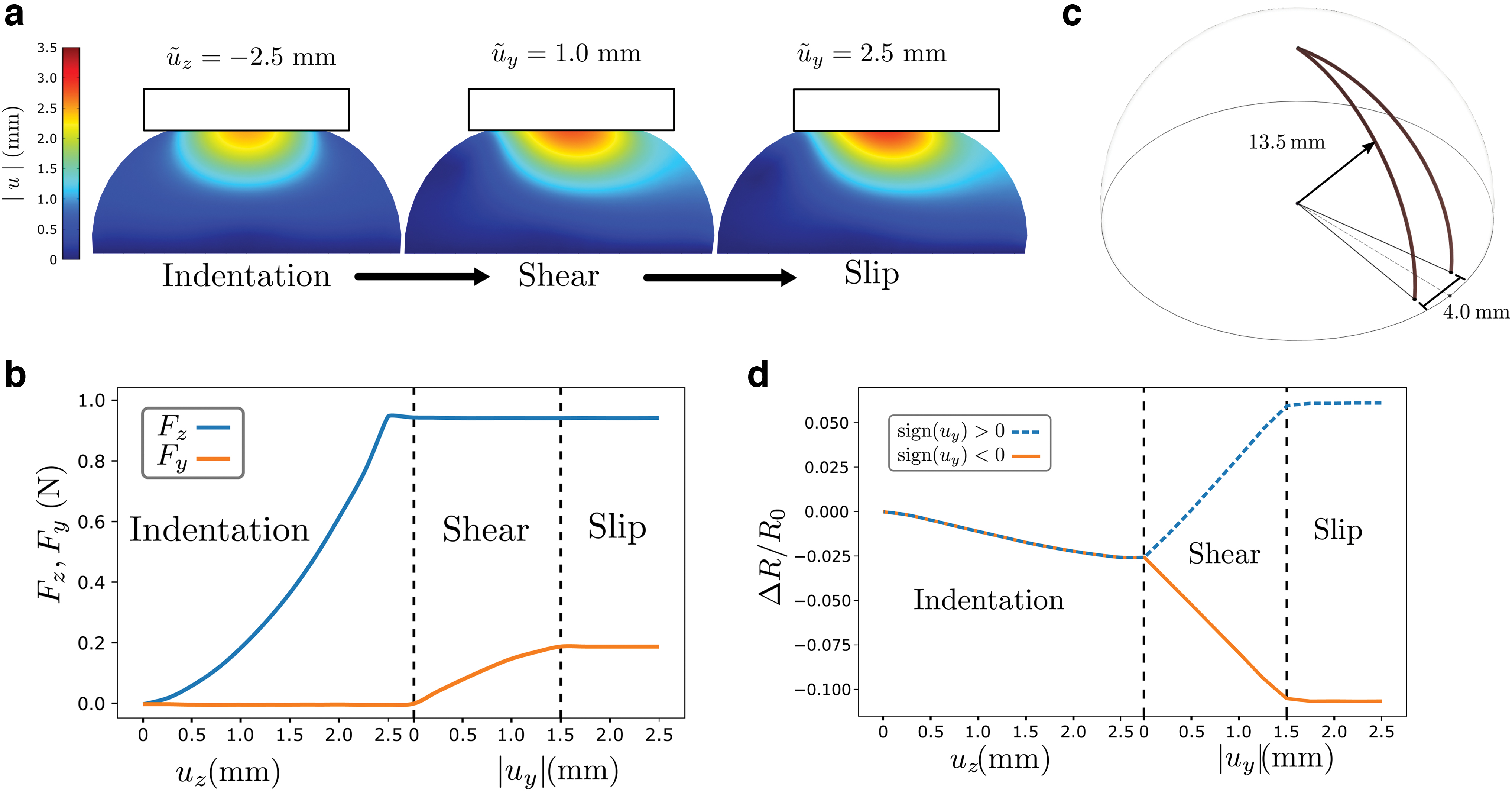
Subsequently, sensitive elements of tangential forces are envisioned using two conductive filaments in semiarches, joined at the top, and separated by a distance of 4 mm at the base of the semispherical matrix (Fig. 8c). This structure is oriented in the direction of the horizontal movement, and the response of the sensor is evaluated in both directions of movement. The sensor has a linear response to compression. In the shear stage, the response is also linear to displacement, but it is more sensitive (Fig. 8d). In the sliding stage shear response is constant and determined by the maximal friction sustained by the sliding object, which is consistent with frictional laws.
To distinguish the shear signal from the compression signal, an additional symmetric circuit, located in the opposite quadrant, is added (Fig. 9a). Thus, defining the reading of circuits in the positive and negative quadrants as

Conclusion
This 3D printing methodology is able to print a resistive channel immersed within a soft body and has facilitated the manufacture of prototype semispherical soft sensors, which are able to respond to both linear and nonlinear compression. The preparation methodology of the soft spherical matrix requires minimal molding, and the sensitive elements can be installed simultaneously in a single step. The combination of the spherical soft matrix, together with the geometry of the sensitive elements, produces sensors that are suitable for handling or robotic grasping. Indeed, the spherical shape gives an increased contact area at greater forces, maintaining low pressure and enabling fragile objects to be suitably handled. Furthermore, the position of the sensitive element enables the simultaneous assessment of normal and tangential forces that occur during this process. This is demonstrated in this work through the development of a simple shear sensor mounted in a gripper device able to handle an object using as a feedback control the compression and the shear forces provided by a two-quadrant hemispherical sensor. Diode type sensors, linear response and combined, and normal and shear forces are suitable choices for a wide variety of applications, for example, these sensors can be specially designed to respond at a specific value of indentation or deformation. This strategy may prove useful in the control of biomechanical devices. Table 1 summarizes the main characteristics of the different sensors developed along this study and allows to compare them.
Summary of Sensor Characteristics
Finally, the accuracy of the numerical methodology used in this study to estimate changes in both the cross section and elongation along a channel could be improved. The methodology is more accurate when the conductive elements are positioned so the channels follow the geometry of the principal axis of stress. This is since the gel used to fabricate the conductive elements cannot be subjected to significant shear stress at the channel's boundaries. Furthermore, in practice, locating channels along the principal axis gives a monotonic sensor response.
Footnotes
Author Disclosure Statement
The authors have no conflict of interest.
Funding Information
F.M. acknowledges ANID-Chile for financial support through projects N° 1201013 and Fondequip N° 130149. Support from LIA-MSD France-Chile (Laboratoire International Associé CNRS, “Matière: Structure et Dynamique”) is greatly acknowledged. The authors acknowledge the support from DICYT Grant 041931MH-POSTDOC of Universidad de Santiago de Chile. A.I. acknowledges the support from Conicyt National Doctorate Scholarship N° 21170673. B.D.T. was supported for this work by ANR PIA funding: ANR-20-IDEES-0002.

References
Supplementary Material
Please find the following supplemental material available below.
For Open Access articles published under a Creative Commons License, all supplemental material carries the same license as the article it is associated with.
For non-Open Access articles published, all supplemental material carries a non-exclusive license, and permission requests for re-use of supplemental material or any part of supplemental material shall be sent directly to the copyright owner as specified in the copyright notice associated with the article.
