




Abstract
The manufacturing method of soft pneumatic robots affects their ability to maintain their impermeability when pressurized. Pressurizing them beyond their limits results in leaks or ruptures of the structure. Increasing their size simultaneously increases the tension forces within their structure and reduces their ability to withstand the pressures necessary for them to operate. This article introduces the use of hot air welding to manufacture three-dimensional inflatable elements containing only lap seals which can sustain larger tension forces than the fin seals used in most other inflatable robotic arms. This manufacturing technique is then used to form inflatable joints with 2-degrees of freedom (DOFs), which can be assembled to form 6-DOFs robotic arms. A dual-arm inflatable robot was built using two arms each with a length of 85 cm, was capable of lifting payloads up to 3 kg, had a large range of motion, and was able to lift misaligned boxes using its two arms relying only on friction force by pushing on both sides of the box. The arm concept was then scaled to form a robotic arm with a length of nearly 5 m, which was able to pickup and place a basketball in a basketball hoop from the free-throw line several meters away. The present work advances the state of the art in building large-scale soft robotic arms.
Introduction
Soft pneumatic actuators function through the force produced by a pressure differential across the surface of the actuator, and their structure can be composed from a wide range of materials, including polymers, plastic films, technical textiles, and others.1–3 Their good actuation characteristics coupled with their inherent compliance make them suitable for a wide range of applications ranging from exploration to human-assistive robotic arms.4,5 However, these actuators must remain impermeable to function and excessive leaks, tears, ruptures, punctures, or permanent deformations can prevent them from functioning properly. But, as soft robots get larger, so do the forces acting on their components and their chances of failure. So, the development of better manufacturing methods for soft fluidic actuators is necessary for large-scale applications.
Polymer-based soft pneumatic actuators consist of cavities within a polymeric structure that expand upon pressurization.6,7 The polymer forming the bulk of the actuator needs to be cured in a mold to assume the desired shape, but enclosed cavities generally cannot be formed in a single molding process. Various methods to join two surfaces of cured polymer parts have been used, including using prepolymer as glue,8,9 using excimer light to reactivate bonding capabilities, 10 and using silicone adhesive to join the polymer to rigid parts. 11 Some methods have been used to facilitate or expedite the manufacturing of these actuators such as the encapsulation of rotationally casted polymeric chambers, 12 and single-step polymer casting using a lost wax process to form internal channels. 13
These actuators can also be three-dimensional (3D) printed in a single manufacturing step using flexible or stretchable materials.14–18 Their fabrication is simplified by the thickness of their matrix, which allows polymer parts to adhere to each other over a sufficient surface. However, polymer-based soft pneumatic actuators mostly rely on stretching of their membrane to perform a motion and would require a thicker and heavier membrane to sustain the larger forces required by large-scale soft robots.
Thin film-based soft actuators are a lighter alternative to polymer-based soft actuators, but present new design and manufacturing challenges. The simplest manufacturing method for film-based actuators is to use heat sealing around their edges to form a volume that can then be deformed when inflated. 19 Simple folded tubes can form bending actuators that function through unfolding, 20 partially sealed at regular intervals to form pouch motors that can produce a longitudinal contraction, 21 and constrictions can be added along a tube at regular intervals to form series pneumatic artificial muscles. 22
Pleats and folds can be added to the flat structure to perform bending or helical deformations,23–26 and stacked pouches can be used to generate torques that can be used to form 2-degrees of freedom (DOFs) robotic arms, 27 or they can be paired with 3D-printed honeycomb structures to form continuum robotic arms.28,29 Laser welding has been used for such film-based structures, but the actuators that made use of this technique could not produce significant forces. 30 However, these structures are often prone to delamination at the seal, degradation of the material around the seal due to heat, and rupture of the material itself.
Some solutions have been proposed to reinforce these actuators such as placing impermeable film bladders inside of stronger permeable fabrics to build inflatable exogloves or robotic arms,31,32 and using technical textiles consisting of a strong fabric coated with an impermeable film that can be heat sealed on their edges to manufacture wearable devices.33–36 The quality of the bond can be improved using heat presses with masks to selectively bond the structure with high applied forces to build structures such as simple robotic arms.37,38 This method has been reported to be able to produce maximum seal strengths of 64 N/cm in a T-peel test. 39 They can be connected mechanically on their bonded segments using techniques such as sewing to form more complex structures, including a 3-DOFs robotic arm.40,41
These film-based actuators are lightweight which would give them a good potential for scalability, but current sealing approaches based on the simultaneous application of pressure and heat for bonding layers introduce limitations in how the parts can be sealed. Some other methods for sealing such film-based structures such as ultrasonic welding and radiofrequency welding could be used but have not yet been investigated for the development of soft pneumatic robots. 42
In this work, we introduce the design and manufacturing of inflatable chamber manufacturing through hot air welding to build large-scale inflatable robotic arms containing exclusively lap seals. These lap seals allow the structure to withstand large tension forces and thus to be scaled up in size without failure of the structure. A comparison of the sealing force of fin and lap seals is followed by an explanation of the fabrication process for basic 3D elements such as cylinders and spheres.
This manufacturing method is then used to build a dual-arm inflatable robot with meter-scale inflatable robotic arms with 6-DOFs each capable of a large range of motion and lifting payloads up to 3 kg. This robot is demonstrated to be able to lift misaligned boxes using the inherent compliance of its inflatable arms. Finally, an inflatable robotic arm with a length of nearly 5 m is demonstrated to be able to place a basketball within a hoop from several meters away.
Methods
Comparison of fin and lap seals
Laplace's Law says that the tension T in the walls of thin-walled pressure vessels is dependent on both the pressure P of the container's fluid and its principal radii of curvature R1 and R2; it can be written as
As larger objects generally have larger radiuses, it follows that their walls will be under increased tensions. Transferring this tension force into stress will show that thicker wall thicknesses are necessary to maintain the stress in the walls to a level similar to that of a smaller pressure vessel with the same internal pressure.
In an inflatable structure, the tension in the walls is transmitted through the material and through seals made in the structure to render it airtight. As using thicker material is fairly straightforward, failure is likely to occur in the seal. Two main types of seals are used in these structures: fin seals where both interior edges of the film are sealed together such that the bonded section sticks out like a fin (Fig. 1a), and lap seals where the exterior of one film is sealed onto the interior of other film (Fig. 1b). This results in fin seals having a force concentration at the opening point of the seal due to the normal force and the lap seals having a distributed force throughout the bonding area.

Explanation of the
The seal strengths of fin and lap seals were evaluated for samples made with two different materials and two different manufacturing methods. The first material is a technical textile with a thickness of 0.25 mm consisting of 210 denier nylon coated with a thermoplastic polyurethane layer sealed using a hot press (QMESYS, QM900L) (Fig. 1c). This material does not stretch and is easy to seal using inexpensive equipment, which makes it a popular choice for soft roboticists. The hot press was used with press force of 2 ton and an applied temperature of 180°C for 150 s. The second material is tarpaulin with a thickness of 0.50 mm consisting of 1000 denier polyester fibers coated with polyvinyl chloride sealed using a hot air welding machine (Fig. 1d). Tarpaulin is a heavy-duty material with high abrasion resistance and tear strength, which are excellent properties for an inflatable robot.
The hot air welding machine (Danrel Industrial Co., DR-T300B) used a nozzle width and roller widths of 10 mm and a sealing speed of 10 mm/s. Additional details about the hot air welding process and the applied pressure are shown in the Supplementary Data. Samples with seal lengths of 5, 10, 15, and 20 mm all having a width of 10 mm were manufactured from both materials and both seal types.
The seal strength was measured by evaluating the maximum separation force of the two ends of each sample using a tensile testing machine (Mark-10, ESM-750FE) with a pulling speed of 0.5 mm/s. In the case of the nylon samples, all lap seals required a similar force to separate, and the lap seal with a seal length of 10 mm had the highest seal strength requiring ∼159 N to separate while fin seals with the same seal length required ∼100 N to separate.
The fin seals failed through delamination of the seal, while the lap seals failed through rupture of the material. In the case of the tarpaulin, fin seals separated easily at a value of ∼35 to 40 N for all seal lengths, while the lap seal required 520 N at a seal length of 10 mm. The failure mode was through the separation of the seal for fin seals and for the lap seal with a length of 5 mm. The longer lap seals failed through material failure. The fin seal separated gradually from the joining edge, while the lap seal sample separated in a single step as the large sealing area distributed the force, as shown in the Supplementary Video S1. This explains the order of magnitude difference in seal strength between the two types of seals. Additional information for comparison of the T-peel strength of both sealing methods and information of the seal failures are included in the Supplementary Data.
Manufacturing of 3D shapes with lap seals
Previous approaches used to building inflatable structures have relied on the application of a heating element to the surface of stacked layers of materials. A single seal can easily be made using a lap seal when both sides of the seal can be accessed by the heating element, but a minimum of one seal in a hermetic structure will require sealing with all heating elements on the outside of the structure during the final step.
Attempting the manufacturing of lap seals through thermal sealing during this final step requires one layer to be stacked on top of the two layers intended to be sealed potentially resulting in sealing of the three layers (Fig. 2a). This reduces the accuracy of the seal, can lead to poor sealing, undesired sealing of some layers, and is impractical in more complex parts where multiple edges that intersect may intersect at a single point. Thus, fin seals have generally been used when manufacturing inflatable soft robots.

Comparison of manufacturing using
This work uses a hot air welding machine which projects hot air laterally between two layers of material while rollers apply pressure on all layers as they move through the rollers (Fig. 2b). The flow of hot air heats only the surface on which the air is projected, and this allows the sealing of only the desired two layers. This can be used to manufacture inflatable chambers containing solely lap seals even in the presence of multiple superposed layers caused by the junction points of multiple seals in more complex parts. Another advantage is that the length of the seal is not limited by the length of the heating element as the layers move through the rollers, which allows for a continuous seal of any length.
Manufacturing a sealed cylinder using hot air welding involves first cutting two circular end covers and a rectangular surface used as the body of the cylinder with a small hole in which the pneumatic fitting is inserted (Fig. 2c). One circular end cover is lap sealed with the rectangular surface while rotating the end cover by either using a different speed for each roller or pulling the sealed portion in a circular trajectory. The opposite end cover is then similarly lap sealed on the opposite edge. The pneumatic fitting can then be inserted and fixed while having access to both the inside and the outside of the cylinder. The last edge is then sealed with the segment of the seal at each end having three layers and with the entire cylinder being passed through the rollers and the air nozzle projecting air only between the two segments to be lap sealed. This results in the volume being sealed using only lap seals.
This approach can be repeated even for large sized elements by scaling all elements and using the same sealing pattern. Some examples of the capability of this method include a soccer ball combining 12 black tarpaulin pieces with a manually cut central white tarpaulin pieces (Fig. 2d) and a cylinder with dimensions four times larger than the previous cylinder (Fig. 2e). Both structures contain only lap seals and were inflated up to 100 kPa without rupture or failure.
Dual-Arm Inflatable Robot
Concept and assembly
The basic element of the joints of the proposed dual-arm inflatable robot is shaped as a rounded triangular prism with slanted ends made from a single piece of tarpaulin sealed into an airtight chamber using two tabs that are folded and sealed (Fig. 3a, b). Three of these elements are then fixed using bolts at each end to rigid plates such that the length at the external side of the joint is longer than that on the inside. This creates a length constraint at the center of the actuator where the external portion of each element tries to unfold to increase its volume and causes a decrease in volume of the other elements (Fig. 3b). The balance in pressure between the elements can then be used to the 2-DOFs orientation of the joint (Fig. 3c). Results for the maximum angle, maximum angular velocity, response speed, and cyclic test of 2-DOF joints of different sizes are included in the Supplementary Data.
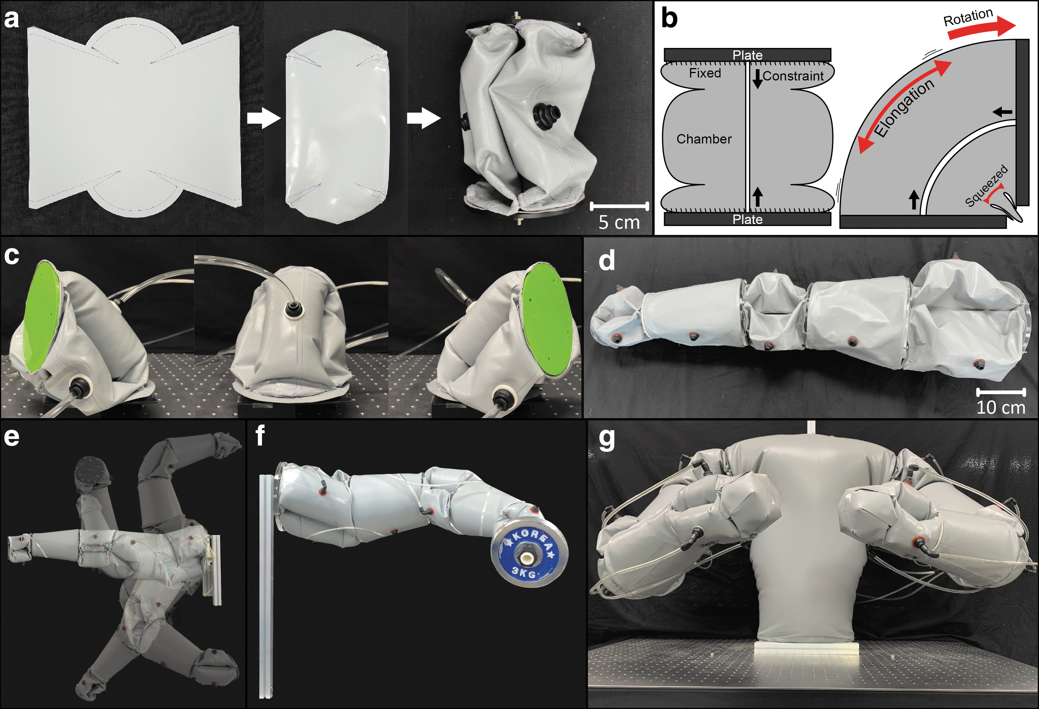
A 6-DOFs inflatable robotic arm with a length of 85 cm was then built by connecting three such 2-DOFs joints with cylindrical upper arm and lower arm elements (Fig. 3d). The joint is capable of a maximum bending angle of ∼85° which gives the arm a large range of motion (Fig. 3e, Supplementary Video S2), and the arm was tested for handling payloads up to 3 kg (Fig. 3f). An inflatable torso with an internal rigid support was built, and two arms were attached at opposite ends of this torso onto the rigid support (Fig. 3g).
Box lifting with positioning uncertainty
The dual-arm inflatable robot contains a total of 23 individual inflatable elements where each of the three joints of each arm contains three inflatable elements each, and the remaining five elements correspond to the torso of the robot and the upper and lower arms of each arm. The robot is intended for lifting boxes by pushing the tips of both arms onto the box and to utilize the friction force generated from the normal force applied onto the box by each arm. Thus, the arms should move in a mirrored manner to realize this motion.
The 18 inflatable elements of the six joints were connected to nine pneumatic regulators such that each element is connected to the same regulator as the opposite element on the opposite arm to produce this mirrored motion. The remaining five elements were connected to a single regulator. The nonactuating inflatable elements were all set at a pressure of 5 kPa, and a sequence of inflation was set such that the arm began far from the body, moved toward the center of the body as to push on any object in front of the body, and then lifting both arms from the shoulder to produce a lifting motion (Fig. 4a).

This strategy can be used to lift objects such as a box without any specialized lifting end effectors or without grabbing the box from the bottom (Fig. 4b, Supplementary Video S3). This motion can also be used to lift objects whose location is unknown since the compliance of the arm making contact before the other will simply push it until contact is made by the other arm. This was tested by positioning boxes with a weight of 160 g and dimensions of 28 cm in height, 41 cm in width, and 31 cm in depth at different positions in front of the arms. The origin of the grid was set as the middle point between the arms in the x-direction and as the line through which the ends of the arms meet in the y-axis.
The success rate for lifting boxes for four different trials with position offsets in increments of 10 mm in the x-direction and 5 mm in the y-direction was measured (Fig. 4c). The result of this experiment shows that the dual-arm robot can lift boxes with moderate success of ∼0.5 to 1.0 if the box is located within a triangle from the base of the robot to the origin of the grid. This is because the arm pushes on the box such that it rotates out of the way without being pushed toward the other arm. So, the robot would need to move sufficiently close to the box such that its center of mass remains within this triangle.
Next, the success rate for five trials for boxes of different sizes was measured where the box sizes are based on standard Korean post office box sizes (Fig. 4d). The dimensions of each box are given in the legend of the figure. Results show that the dual-arm robot has the highest success rate when boxes have sufficient size for the arm to position themselves correctly and stay within the range where the arms can produce a sufficient lateral force. Large boxes resulted in the arms being unable to position themselves adequately while smaller box sizes were outside of the range of the arms. Next, the box of size 4 (width: 41 cm, depth: 31 cm, height: 28 cm, weight: 160.3 g) was tested for five trials for different box weights ranging from 160 to 560 g (Fig. 4e).
The dual-arm robot's success rate decreased almost linearly until failing every trial at 560 g. It is to be noted that the lifting capability could be increased using more specialized grippers that produce higher friction forces such as gecko-inspired grippers or ones that do not rely as much on friction such as suction cups.
Large-Scale Inflatable Robotic Arm
The concept of the proposed inflatable robotic arm can be scaled in size if the inflatable chambers can withstand the tension forces that they transmit and if the rigid parts can withstand the mechanical forces that they are subject to. A large-scale inflatable robotic arm was built to test the upper limit of the proposed concept in terms of size. To this end, the rigid plates used in the joints were replaced with 5 mm thick aluminum plates, and additional plates were added on the inside of the inflatable chambers of the shoulder joint.
The inflatable chamber of the shoulder joint was scaled such that the dimensions of the shoulder joint are 40 cm in diameter and 40 cm in height, which are approximately twice the dimensions of the inflatable shoulder joint used in the dual-arm inflatable robot and four times that of its wrist (Fig. 5a). The total length of the large-scale inflatable robotic arm is 4.95 m with the shoulder and elbow joints having a length of 0.4 m each, the upper and lower arms having a length of 2 m each, and the wrist joint having a length of 0.15 m (Fig. 5b). The total weight of this arm is 16.85 kg with the shoulder joint having a weight of 7.75 kg, the upper arm having a weight of 2.02 kg, the elbow joint weighting 4.53 kg, and the forearm weighting 2.55 kg.

An inflatable gripper made from paired pouch motor patterns presented previously by our group was attached at the end of the large-scale inflatable robotic arm such that the length from the base of the arm to the palm of the gripper is ∼5 m. 41
The large-scale inflatable robotic arm was installed on an outside basketball court at the free-throw line 4.60 m from the board with the hoop being 3.05 m off the ground, and a basketball was positioned in diagonal in front of the inflatable arm. In open-loop control, the inflatable robotic arm was made to reach for the basketball, grab it, lift it, the arm was extended in a nearly straight position to place the basketball over the hoop, and the basketball was then released through the hoop. The basketball weighs 624 g and was able to be lifted off the ground and the arm fully extended while holding the basketball.
Some of the largest issues encountered while doing this experiment were related to oscillation of the arm during the regulation motion. This occurred due to the large momentum generated during its motion against the high compliance in the joints and the increased external torque produced by the wind forces acting on the large structure itself, as can be seen in the Supplementary Video S4. The length of this arm is comparable with the largest industrial robotic arms yet weighs and costs multiple orders of magnitude less, and it can be safely handled by and around humans.
Discussion
The development of inflatable robotic arms composed entirely of inflatable elements sealed using lap seals manufactured through hot air welding was demonstrated in this article. Two main demonstrations were presented where the first is a dual-armed robot used for lifting misaligned boxes by pushing on both sides of the box. The maximum payload of this robot is smaller than current collaborative robots by nearly an order of magnitude and is likely to be insufficient for most industrial applications.
However, the robot arms had a very large range of motion and is the first example of dual-armed soft robot capable of lifting objects by making use of their compliance as part of the grasping motion. It demonstrates the potential that soft robotic arms have in dealing with uncertainties and repositioning objects that are located within their work area. One of the main limitations in the performance of this robot is that the grasping range of the boxes is within the maximum range of motion of the arms.
Either increasing the range of motion of each arm or changing their position or assembly could improve the performance of the system. The second application was a robotic arm with a total length approaching 5 m. This is one of the largest soft robots in the literature. The only longer soft robotic arm corresponds more to a floating structure that is not intended to grasp and move payloads. 43 A comparison with other soft robotic arms shows that they have a good overall performance in terms of demonstrated payload, range of motion, DOFs, and length (Table 1).
Comparison of Soft Robotic Arms
Estimated.
Based on simulation results.
These two implementations also highlight some of the disadvantages of large-scale inflatable soft robots. In the 5-m-long robot arm, there are some oscillations before the robot settles after a motion as the air within the robot is compressible which gives all components some compliance. Precision positioning and repeatability of the arms were not tested, and all experiments were done with open-loop control, but the repeatability of the motion will be problematic due to nonlinearities that occur due to friction in the material and between adjacent chambers of the joints. A sensor would be required to measure the angle for feedback control, but rigid surfaces do not intersect such that simple rotary encoders cannot be used. Instead, multiaxis sensors such as inertial measurement units should be used to measure the rotation and translation of each joint.
Through the fabrication and use of large-scale inflatable robots, it was found that the limit in the possible pressure within the robots came not from the seals but rather from the rigid parts used in the fabrication of the joints. Additional information about the location and types of rigid parts in each arm is included in the Supplementary Data. The most typical failure point was in the rigid plates used at the interface between joints and members as the elements of the joint produce a high torque on the plate which can buckle or snap it. The base joint of the 5-m-long robot arm even used plates both externally and inside the joint elements to better distribute the forces. Another failure point of the 5-m-long robot arm was the bolts used to fix the joint to the rigid plate caused by either snapping of the bolt or thread failure, so the number of bolts was increased to better distribute the load.
Conclusion
This work introduces the use of hot air welding to build 3D inflatable elements where every seal is made from lap seals. The use of hot air welding enables the selective sealing of stacked layers and to produce inflatable structures composed solely from lap seals, whereas inflatable structures that are thermally sealed using the direct application of heat require at least one fin seal. In our testing, tarpaulin with fin seals was capable of withstanding 40 N while the same material with lap seals could withstand 520 N, which exceeded the values of 100 and 159 N for thermally sealed technical textiles using fin and lap seals, respectively. This allows for the inflatable elements to sustain large tension forces within their structure and thus to be scaled up in size to form human-scale inflatable robotic joints.
Multiple of these joints were used to build a 6-DOFs inflatable robotic arm with a length of 85 cm capable of a large range of motion and of handling payloads up to 3 kg. Two of these arms were then used to build a dual-arm inflatable robot that can lift boxes of various dimensions and misalignment using the friction force generated by pushing on the box. Finally, a large inflatable robotic arm with a total length of 5 m was built and made to pick up a basketball and place it in a basketball hoop from the free-throw line. These inflatable robotic arms demonstrate the importance of improving the assembly method of inflatable structures to increase their limits in terms of performance and size.
The main physical limitations of the tested robotic arms were shifted onto the rigid elements used to join the different volumes such as the rigid plates and the bolts as these began to fail at high pressures and high payloads. All robotic arms were operated in open-loop control, and multiple challenges are expected to be able to operate this kind of robotic arm accurately in closed-loop control. Due to the lack of a defined rotation point and exact analytical solution, suitable sensors should be implemented together with an effective control method to deal with the significant nonlinearities.
The fabrication of large-scale inflatable elements can be used for other robotic applications beyond robotic arms and could be used in applications such as legged robots, medical devices, etc. In addition, these inflatable structures are significantly lower cost and lighter than their rigid counterparts such that they have significant potential for wide implementation if their controllability is improved. Future work will focus on the improvement of the design to decrease loads on the rigid parts, on the implementation of sensors and control methods, and on using this kind of robotic arm in the field of logistics.
Footnotes
Author Disclosure Statement
No competing financial interests exist.
Funding Information
This work was supported by the Technology Innovation Program (20008908) funded by the Ministry of Trade, Industry and Energy (MOTIE, Korea), by the National Research Foundation of Korea (NRF) grant funded by the Korea government (Ministry of Science, ICT and Future Planning) (2020R1A4A1018227), and by the 2019 Global Ph.D. Fellowship Program through the NRF (National Research Foundation of Korea) Grant funded by the Korean Government, Ministry of Education (2019H1A2A1076417).

References
Supplementary Material
Please find the following supplemental material available below.
For Open Access articles published under a Creative Commons License, all supplemental material carries the same license as the article it is associated with.
For non-Open Access articles published, all supplemental material carries a non-exclusive license, and permission requests for re-use of supplemental material or any part of supplemental material shall be sent directly to the copyright owner as specified in the copyright notice associated with the article.
