




Abstract
The gold standard treatment for bladder cancer is radical cystectomy that implies bladder removal coupled to urinary diversions. Despite the serious complications and the impossibility of controlled active voiding, bladder substitution with artificial systems is a challenge and cannot represent a real option, yet. In this article, we present hydraulic artificial detrusor prototypes to control and drive the voiding of an artificial bladder (AB). These prototypes rely on two actuator designs (origami and bellows) based either on negative or positive operating pressure, to be combined with an AB structure. Based on the bladder geometry and size, we optimized the actuators in terms of contraction/expansion performances, minimizing the liquid volume required for actuation and exploring different actuator arrangements to maximize the voiding efficiency. To operate the actuators, an ad hoc electrohydraulic circuit was developed for transferring liquid between the actuators and a reservoir, both of them intended to be implanted. The AB, actuators, and reservoir were fabricated with biocompatible flexible thermoplastic materials by a heat-sealing process. We assessed the voiding efficiency with benchtop experiments by varying the actuator type and arrangement at different simulated patient positions (horizontal, 45° tilted, and vertical) to identify the optimal configuration and actuation strategy. The most efficient solution relies on two bellows actuators anchored to the AB. This artificial detrusor design resulted in a voiding efficiency of about 99%, 99%, and 89%, in the vertical, 45° tilted, and horizontal positions, respectively. The relative voiding time was reduced by about 17, 24, and 55 s compared with the unactuated bladder.
Introduction
Urinary bladder cancer is among the 10 most common cancer types in the world, with ∼550,000 new cases every year. 1 For muscle-invasive bladder cancer, the gold standard treatment is radical cystectomy (RC) that implies the removal of the organ. To date, the standard approach coupled to RC is urinary diversion. In this procedure, the urine flow can be rerouted from ureters to external bags attached to the patient's abdomen as in ureterocutaneostomy and ileal conduit urinary diversion. In other cases, the bladder is surgically reconstructed with bowel segments (heterotopic and orthotopic bladder). 2 Despite being widespread in clinical practice, all these interventions imply severe complications and do not allow controlled voiding as in the native counterpart. Indeed, voiding is typically achieved by self-catheterization or by applying external abdominal pressures (e.g., Valsalva maneuver) with a significant impact on patient's quality of life.3,4
Only few attempts were pursued to deal with the aforementioned complications by replacing bladder functions with bioartificial (based on regenerative medicine)5,6 or artificial systems.7–9 However, in the former case, bladder tissue regeneration is still at an early research stage, and in the latter, none of the artificial bladder (AB) systems proposed in the past showed satisfactory performances. The main failure reasons were related to the lack of a proper structure able to expand controllably as the natural bladder, to guarantee a low residual volume, and to avoid urine leakages, encrustations, and infections. 10 While replacing urinary system function, guaranteeing continence appears crucial. Endourethral 11 and extraurethral12,13 artificial sphincter devices witnessed some success stories in the past years14,15 by also reaching the market.
On the contrary, only few works addressed active voiding of the bladder by detrusor mimicking. Artificial detrusors based on thermoresponsive hydrogel 16 or shape memory alloys (SMAs)17–20 were devised to physically contract the native bladder on demand as a natural detrusor does. However, the proposed devices were designed and tested only on small animals' bladders, with 0.2–50 mL of capacity. Furthermore, SMAs imply heating that may damage the surrounding tissues, besides slow activation and deactivation phases. So far, the only AB designed to void automatically was proposed by Zhuo et al. 21 and relies on electromechanical actuators operating in a compression mode to produce micturition. However, the devised voiding principle implies the inclusion of rigid components that hamper AB implantability.
Hence, the quest for a fully implantable artificial system that collects urinary fluids and controllably voids while guaranteeing safe and efficient implantability still persists. Inspiration for suitable actuation strategies coping with the aforementioned objectives might come from other actuation strategies proposed in literature to reproduce muscle-like contraction in impaired organs different from the bladder. In this regard, electroactive polymer, 22 pneumatic,23–25 and above all hydraulic actuators12,13,26 were successfully proposed.
Due to their muscle-like operation, fluidic actuators appear interesting when trying to reproduce detrusor function. Among them, hydraulic ones appear particularly promising compared with pneumatic solutions in light of a lower compressibility of the fluid and a higher force-to-volume ratio. 27 Furthermore, if driven by physiological liquids, they are safer during surgical procedures or in implantable systems, while reducing the risk of bursts. 28
In this article, the authors propose two hydraulic actuator designs to be combined with an AB structure 29 and explore different arrangements of the aforementioned designs to maximize the voiding performances. Both the actuators and the AB are featured by flexible structures composed of biocompatible materials to guarantee safe implant. The proposed actuation system includes also an electrohydraulic circuit and a reservoir to guarantee full implantation of the entire apparatus. In the following sections, an overview of the system and the voiding strategies is first presented, followed by the design and fabrication of the constitutive components and the experiments for their validation. The overall system performance was assessed evaluating the active voiding by varying the actuator type, number, and distribution over the bladder to identify the most efficient solution. Lastly, the results and discussions are presented.
System Overview and Voiding Strategy
The proposed implantable system includes the following: (1) an AB, (2) ureters and urethral connections with valves, (3) an artificial hydraulic detrusor, (4) a reservoir, and (5) a control unit for voiding management (Fig. 1A).

System overview.
The AB is based on a design patented by some of the authors. 29 It consists of a flexible and self-foldable hollow structure that varies its inner volume without undergoing elastic deformations, thus also favoring the presence of urine-resistant coatings. 30 To meet physiological requirements, it is designed to change its volume from ideally 0 (empty configuration) to 300 mL (full configuration), thus resembling a natural bladder volume. 31 To this aim, the lateral walls are conceived to self-fold, thus making the two larger walls approach each other (Fig. 1B). The AB has maximum thickness c, side length u, and width b of 35, 136, and 90 mm, respectively.
Previous work from the authors revealed that these dimension enable optimal fitting with the pelvic cavity, intended as a target implant site. 32 It is provided with connections to be anastomosed to the residual ureters and urethral segments, thus allowing urine to flow from the kidneys to the AB and out of the body. In this study, a mechanical and a check valve are inserted in the connections to guarantee continence and avoid reflux, respectively.
The main feature of the system is the presence of an artificial detrusor to allow active voiding. The detrusor actuation principle should fit AB geometry, feature reduced encumbrance, and favor complete bladder voiding. Two fluidic and foldable actuator types were designed and consist of origami 33 and bellows structures,34,35 operated by negative and positive differential pressures, respectively. The origami actuator includes a foldable zigzag skeleton (with a number of units M ≥ 2, Fig. 2A) enclosed in a flexible skin, filled with fluid (water). The actuator length varies based on the difference between internal and external pressure.

Representation of the hydraulic actuators developed as artificial detrusor. Origami actuator working principle
When the differential pressure is null, the actuator is in the resting position, whereas it fully contracts when a negative differential pressure is applied due to fluid aspiration (Fig. 2A). By properly fastening one or more pairs of actuators to the AB lateral edges by inextensible belts, their contraction can be exploited to produce the AB-controlled voiding (Fig. 2B). The bellows actuator consists of inextensible chambers stacked together (with a number of chambers N ≥ 2, Fig. 2C). Also in this case, the actuator length depends on the difference between internal and external pressure. When the differential pressure is null, the actuator is flat (resting position), whereas it elongates when a positive differential pressure is applied due to fluid injection (Fig. 2C). By anchoring one or more actuators to the AB larger wall with inextensible belts, their expansion produces belt tensioning, and consequently, AB-controlled voiding (Fig. 2D).
Both strategies are operated by an ad hoc control unit, consisting of an electrohydraulic circuit connected to the actuators and to a fluidic reservoir. The reservoir stores the liquid for actuator activation, while the electrohydraulic circuit allows the liquid transfer from the reservoir to the actuators and vice versa. The system is controlled by an Arduino Nano microcontroller and is powered by a portable battery.
Design and Fabrication
Artificial bladder
The proposed AB is an inextensible self-foldable structure composed of 18 pliable nonstretchable segments. To guarantee the shape transition and the nonstretchability of the structure, the AB was fabricated with two thin inextensible polypropylene (PP) layers, embedding acetate segments. PP was chosen for its biocompatibility,36–38 while acetate serves to selectively add stiffness to the structure and hold the desired shape during filling and voiding.
The fabrication process (Fig. 3) started by designing (1) and cutting acetate segments by a laser cutter (PLS6.150D; Universal Laser Systems, Inc.) (2). The acetate was interposed between the two PP layers with 1 mm interspaces between the segments (3), obtaining a 2D structure, where the interspaces act as flexible hinges for the AB shape transitions. We sealed the external boundaries with a heat sealer (FS-300B; Hualian, China) (4) and removed the residual PP portions outside the sealed boundaries. The structure was folded along the flexible hinges (5) and sealed again to obtain a 3D hollow structure (6) featured by two openings appointed for ureters and urethral connection (obtained from polyurethane [PU] tubes) insertion (7). A check valve (backflow pressure: 500 kPa; opening pressure: 4 kPa) was added in the input tube to avoid reflux, whereas a mechanical valve was used to regulate the output flow.

AB fabrication workflow. The acetate segments were designed
Actuation system
The artificial detrusor design should comply with AB dimensions, implantability constraints, and emptying force. Specifically, AB thickness in the full configuration (3.5 cm) determines the desired origami resting length and bellows expansion. On the contrary, thickness in the empty configuration (3.16 mm) influences the origami-desired contraction to achieve full voiding. AB wall dimensions (a and b, Fig. 1B) set the limit for the actuators possible maximum size. The liquid volume to operate the actuators should be no more than 100 mL. This value was chosen as threshold for the maximum reservoir volume still ensuring implantability, as found in literature for commercial implantable devices. 39
Furthermore, by respecting this specification, the combined detrusor+AB volume still results in line with the physiological bladder normal volume range (300–400 mL). 31 Despite force being not used as a specification when meeting the other requirements, actuators with maximized output force were preferred according to the model equations (Supplementary Data S1, Section I).
As mentioned, we selected two fluidic actuators (origami and bellows) and verified their performances in terms of AB voiding efficiency when varying the design, number, and distribution over the AB. Moreover, to shed light also on the role played by the force distribution over the AB (i.e., bladder surface covered by the actuators and distance between the actuators), two arrangements were investigated for each actuator type, based either on one or two actuators (or pairs of origami actuators for symmetry reasons). Overall, the following four cases were tested (Fig. 4):

Actuator arrangement schematization: origami actuators in cases 1 and 2
- AB +1 origami actuator pair (case 1);
- AB +2 origami actuator pairs (case 2);
- AB +1 bellows actuator (case 3);
- AB +2 bellows actuators (case 4).
To identify the optimal values of the actuators geometrical parameters respecting the design constraints, bellows and origami actuator behaviors were modeled.
An origami actuator can be modeled as a chain of M triangular units enclosed in a massless, flexible, nonstretchable skin. 33 Each unit of the skeleton can be represented as two hinged rigid beams of dimensions D and W, with an opening angle 2θ and length 2L, enclosed in a skin approximated as a parabolic arc of length 2So (Fig. 2A). Considering the actuator resting position with an initial length 2Lo (L = Lo), its contraction ratio can be defined as the percentage ΔL/Lo, where ΔL is the difference between the initial and final length.
A bellows actuator can be modeled as N stacked chambers, approximated as geometric solids with straight edges. 34 Each chamber (dimensions k and l) is connected to its neighboring chambers by a bonded area (dimensions f and g). The bonded area was experimentally set to 1.5 × 2 cm as it allows to cut a hole of a proper size for internally connect neighboring chambers. Thickness t varies as the chamber is inflated (Fig. 2C).
Considering AB dimensions, possible values for actuator parameters (i.e., dimensions and number of units/chambers) were identified for each analyzed case (Table 1). For each combination, a mathematical model allowed to estimate actuator contraction/expansion and the liquid volume needed (Supplementary Data S1, Section I). A set of parameter values guaranteeing the desired performances were selected for actuator prototyping for each analyzed case.
Parameter Values for Actuator Design Optimization
Parameter values used in the design optimization of the origami (cases 1 and 2) and bellows (cases 3 and 4) actuators. D and W are the width and length of the origami skeleton beams and M is the number of triangular units in the actuator (Fig. 2A). k and l are the dimensions of the bellows chambers and N is the number of chambers in the actuator (Fig. 2C). The reported ranges use the notation “starting point:step:end point.”
The actuators were fabricated using a heat sealing process as for the AB. The origami actuators were realized by sealing a polyethylene (PE) skin around an acetate skeleton (Fig. 5A). The material of the skin is flexible and nonstretchable to avoid undesired deformations, which would reduce the actuator performance. Specifically, the fabrication process started by designing (1) and cutting the skeleton from an acetate sheet by a laser cutter (2). The skeleton was zigzag folded (3), interposed between two PE layers (4) and fixed with double-sided tape (5). We heat sealed the PE skin along the borders (6), leaving an opening to insert and glue a PU tube (7). The bellows actuators were realized in PP (Fig. 5B). To selectively bond the chambers in the middle portion, enabling connection and fluid passage between neighboring chambers, an acetate mask with a central rectangular hole was also used.

Actuator fabrication workflow. Origami actuators
Specifically, the fabrication process started by designing (1) and cutting PP and acetate layers into the desired shape by a laser cutter (2). The acetate was interposed between the two PP layers (3) before heat sealing the middle portions (4). We removed the acetate mask (5) and cut a hole in the sealed portion to internally connect the chambers (6). We overlapped another pair of PP layers on the top and bottom sides (7) and heat sealed along the borders (8) to have a bellows structure, leaving an opening to insert and glue a PU tube (9). To integrate both actuators on the AB, we used inextensible belts. Each origami pair was anchored to both the AB larger walls with two acetate belts. To compress the AB by exploiting the actuator contraction, the belts were as long as the actuators and as wide as the bladder wall.
Each bellows actuator was fastened with two PP belts, wrapping the AB transversally and longitudinally. To compress the bladder during the actuation, the belts length was defined experimentally to be completely taut when the actuator was elongated.
Control unit and reservoir
As a proof of concept of an integrated prototype, an ad hoc control unit was developed to fill and empty both types of actuators from the reservoir.
The reservoir consists of a flexible chamber, fabricated by heat sealing two square PP layers along the borders (side length: 80 mm), that stores the liquid volume for the actuation with a maximum capacity of 100 mL. The control unit includes a hydraulic circuit and control electronics (Fig. 6A). The hydraulic circuit comprises two pumps (SP 270 EC-L; Schwarzer Precision, Germany) and two solenoid valves (Series 3; Parker Hannifin) (Fig. 6B), selected as a trade-off between size, performances, and power consumption to operate the actuators in less than a minute, which would be acceptable for the urination of a patient40,41 (considering a reservoir of maximum 100 mL).

Block diagram of the control unit
Pumps and valves are organized in two lines to enable fluid injection and aspiration from the reservoir to the actuators, respectively. During the actuator filling phase, the flow is directed from the reservoir to the actuators by activating pump 1 and solenoid valve 2 (red line, Fig. 6B), whereas it is reversed during the emptying phase by activating pump 3 and solenoid valve 4 (green line, Fig. 6B). Specifically, the red line is activated first when driving origami actuators to let them reach their resting position and AB filling. The green line is activated to produce actuator contraction when AB voiding is required. On the contrary, when controlling the bellows actuators, the green line is activated first enabling the actuators to reach their resting position and allowing AB filling. The red line is activated to produce AB voiding by actuator expansion.
To control the filling and emptying phases of the actuators, a pressure sensor (MPX5100DP series; Freescale Semiconductor, Inc.) was added at the actuator inlet. Pressure monitoring enabled to detect the filled/empty states of the actuators by means of pressure thresholds, thus to stop the pumping system after filling or emptying the actuators.
The pumps, the solenoid valves, and the pressure sensor were all interfaced and controlled with an Arduino Nano 3.0. As the current required by each component was higher than the maximum Arduino output current, an ad hoc power circuit was designed on a stripboard. The pumps and solenoid valves were controlled by four power MOSFETs, with a gate transistor of 1.5 kΩ and a protective diode at each load. As pumps and solenoid valves work at different operating voltages, a step-down (LM7805) and a boost (MT3608) DC-DC converter were used to power them and the Arduino from a single 7.4V Li-ion battery (Fig. 6C).
Experiments
Before evaluating actuators voiding performances, the optimized designs were characterized in terms of contraction/expansion and required liquid volume (Supplementary Data S1, Section III). This characterization aimed at verifying (1) accordance of experimental data with the model used to steer design optimization, and (2) suitability with the target application.
To assess the efficiency of the actuators as artificial detrusors, we evaluated voiding efficiency (VE: percentage of voided volume with respect to the initial bladder volume), postvoid residual (PVR) volume (volume in the bladder after voiding completion), and voiding time (VT: time needed for the reachable voiding) in case of passive (no detrusor) and active voiding (using the four actuators arrangements controlled by the control unit). This aimed at identifying the best actuation strategy and at evaluating the added value of the artificial detrusor compared with the spontaneous voiding favored by the AB structure itself. To simulate different clinical scenarios (patients lying, sitting, or standing), performances were evaluated at three AB slopes with respect to the horizontal plane (0°, 45°, 90°).
In each experiment, we filled the AB up to its maximum capacity, then opened the mechanical valve at the bladder outlet and weighed the voided volume over time with a precision balance (KERN PFB; KERN & SOHN GmbH, Germany) connected to the PC through serial communication (Fig. 7). For the active voiding experiments, the actuators were in their resting position in the initial condition and the control unit was switched on for the actuation once the valve was opened to start voiding. The pressure thresholds (−10 kPa for origami and 21 kPa for bellows actuators), defined for the characterization (Supplementary Data S1, Section IIIa), were used to monitor the actuators' state and stop the pumping system as the empty or filled state was reached. We repeated each experiment four times (n = 4) and computed mean and standard deviation of the measured variables. For each slope, the one-way ANOVA test (statistical significance set at p < 0.05) was performed to determine statistically significant differences among the passive and active cases.
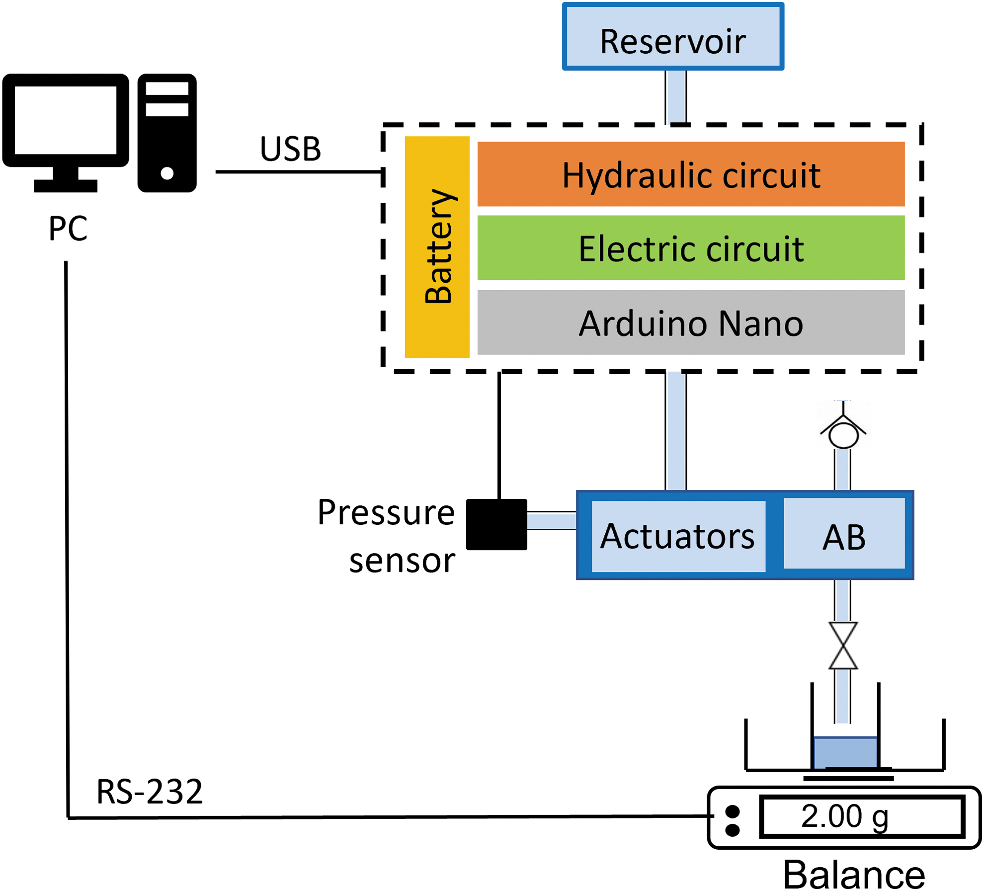
Experimental setup for voiding performance assessment.
Results and Discussions
The optimized actuator designs achieved experimental performances similar to the estimated ones, satisfying the specifications of contraction/expansion and liquid volume (Table 2 and Supplementary Data S1, Section IIIb). The main mismatch between models and experiments is observed for the origami actuators: the experimental contraction ratio results 3% and 11% lower than the predicted one for Case 1 and Case 2, respectively. The contractions may have been hampered by interferences or frictions between the skin and skeleton, which were not taken into account by the model massless skin assumption. Regarding bellows actuators, the experimental data show a higher expansion (difference <3.5 mm) compared with models for both Case 3 and Case 4. This difference may be ascribed to the use of materials with some degrees of flexibility, whose deformation was not included in the model.
Optimal Values of the Actuator Design Parameters and Values of the Contraction Ratio/Elongation and Volume of the Actuators
The optimal values of the actuator design parameters are reported in the four analyzed cases. For each feature (i.e., contraction ratio/elongation and volume), the value estimated by the mathematical model and the one measured experimentally (in brackets) are reported in the four cases. Values refer to the single actuator in each analyzed case.
In all the cases, the measured operating volumes differ of about 4 mL from the predictions, but still fulfilling the requirements. Anyway, differences in actuator performances are also influenced by inaccuracies due to the manual fabrication process.
To obtain an integrated prototype, the origami (Fig. 8A) and bellows (Fig. 8B) actuators were anchored to the AB and connected to the control unit and the reservoir (Fig. 8C). Benchtop voiding experiments showed that when gravity contribution is missing (0° slope), the VE for all four active cases is considerably higher than the passive condition, being statistically significant (p < 0.05, Table 3). However, the origami actuators did not produce a dramatic improvement, increasing VE from 51.0% to 59.5%. These performances may be due to the reduced contraction ratio of the origami, compared with the mathematical model (Table 2), that could hamper the full AB closure, resulting in an incomplete voiding.

Prototypes of the origami actuator
Voiding Efficiency and Postvoid Residual Volume
Voiding efficiency and postvoid residual volume (in brackets) are reported with mean value and standard deviation in the three tested slopes (0°, 45°, and 90°) for the bladder with no detrusor (AB) and with actuation according to the four arrangements (origami: case 1 and case 2; bellows: case 3 and case 4).
p < 0.05 between the selected cases.
AB, artificial bladder.
Compared with the origami actuators, a significantly higher VE was reported by the bellows actuators (cases: 1–3, 1–4, 2–3, 2–4). At 45° and 90° slopes, both passive VE and active VE reached almost 100% (without statistically significant differences), suggesting that the main contribution is gravity (Table 3). Within cases 1–2 and 3–4, there were no significant differences in VE by changing the actuators number, size, and distribution on the AB (only case 4 at 90° resulted statistically and significantly different compared with case 3). This might be due to the similar contact area between the AB and the actuators in the different configurations. To be functional, the actuation should guarantee a PVR volume <50 mL. This is considered a cutoff value for designating the PVR volume as normal and minimizing the risk of urinary tract infections related to urine retention.42,43
In our study, considering 300 mL as bladder volume, only the bellows strategies (cases 3 and 4) satisfied this requirement for all the slopes, demonstrating the feasibility of the proposed approach for a successful bladder voiding (Table 3).
A remarkable VT reduction was witnessed with actuation compared with the passive voiding (Fig. 9). The most appreciable difference was observed in the worst-case scenario (0° slope), where VT is reduced by about one-third with a statistical significance for all active cases (with best performances for case 4: 100.6 ± 2.6 s).

Voiding time needed for not actuated (AB = gray) and actuated AB (origami: case 1 = green and case 2 = red; bellows: case 3 = blue and case 4 = yellow) when varying prototype position (slopes 0°, 45°, and 90°). For each experimental condition, mean and standard deviation are reported. *p < 0.05.
Also with the gravity contribution, the actuation enabled a VT reduction over the passive case both at 45° (AB: 120.1 ± 4.3 s; case 1: 108.0 ± 5.3 s; case 2: 110.9 ± 3.3 s; case 3: 102.9 ± 5.9 s; and case 4: 96.3 ± 2.1 s) and 90° (AB: 107.8 ± 4.5 s; case 1: 101.5 ± 1.8 s; case 2: 98.5 ± 1.7 s; case 3: 86.2 ± 4.2 s; and case 4: 90.5 ± 4.8 s) slopes (Fig. 9). Only case 2 at 45° and case 1 at 90° did not report a statistically significant change in VT over the passive case.
Also for VT, the different arrangements of the same actuator types (cases 1–2 and cases 3–4) achieved similar performances. Bellows actuators significantly outperformed origami actuators at 45° (cases: 1–4, 2–4) and 90° (cases: 1–3, 1–4, 2–3), supporting the suitability of bellows actuators for the target task. Despite the actuation, VT is still high (about 3.5 times longer than the physiological one,40,41 but more practical for patients than catheterization), but this could be improved by exploiting micropumps with higher flow rates.
Conclusions
In this work, we presented two solutions for restoring controlled voiding upon RC, based on foldable and flexible hydraulic actuators to be combined with an AB structure. The only AB equipped with an active voiding system reported so far 21 exploited an electromechanic actuator, but no assessment of the voiding efficiency in relevant operational scenarios (e.g., when considering different patient's positions and clinical conditions) was reported. To the best of our knowledge, there are no works in the literature exploiting flexible strategies and hydraulic actuation for this application.
We designed, developed, and validated the artificial detrusors, which were afterward integrated on the AB with different arrangements and controlled by an ad hoc electrohydraulic circuit for bladder voiding. Benchtop experiments at three different simulated patient positions allowed to evaluate the performances of the two voiding strategies as artificial detrusors. Specifically, we assessed VE, VT, and PVR volume for each actuator type and arrangement to identify the most efficient strategy. At 45° and 90°, the voiding was complete with a negligible PVR volume both in active and passive cases, but VT was significantly reduced with actuation. Without gravity, the active voiding outperformed the passive one, increasing VE and reducing VT both with origami and bellows actuators. There were no dramatic differences in the voiding performances by changing arrangements for the same actuator type, but significant differences were reported between the two actuator types.
In conclusion, the most promising strategy for an artificial detrusor relies on bellows actuators, which achieved a normal PVR volume <50 mL.42,43 Thus, we demonstrated the feasibility of the positive pressure-driven hydraulic actuation in achieving an acceptable AB voiding, even without gravity contribution (which is the condition of many elderly patients lying continuously). In the future, the reduction of the control unit size will be targeted to guarantee the system implantability. 44 A volume sensing circuit,45,46 able to monitor and inform the patient about the filled bladder volume, 32 will be coupled with the hydraulic artificial urinary detrusor and sphincters, 12 for a full restoration of the lower urinary tract functions. The power management will be assessed as well by selecting components reducing power consumption and possibly implementing energy harvesting strategies47–49 toward extended lifetime.
Furthermore, the dynamic interaction of the active AB with the surrounding tissues should be assessed and should drive future evolutions of the implantable system. To this aim, the inclusion in a confinement biocompatible bag might enable safer interaction with the host while also protecting the active components from direct contact with fluids and from the encumbrance of adjacent organs. The interaction with urine and the prevention of encrustations and biofilm formation will also be assessed in the future toward a long-term operation of the system.
Footnotes
Authors' Contributions
All authors conceptualized the system. G.C. and M.I. designed and developed the implantable system prototype. G.C., M.I., and F.S. performed the experiments. V.I. and A.M. supervised the research activity. G.C. wrote the article with contributions from M.I. All authors discussed the results, and commented on and revised the article.
Author Disclosure Statement
No competing financial interests exist.
Funding Information
This work was supported by INAIL, the Italian National Institute for Insurance against Work-related Injuries (noncommercial entity), within the PR19-CR-P2 BioSUP (BIOnic Solutions for Urinary impaired People) project framework.

References
Supplementary Material
Please find the following supplemental material available below.
For Open Access articles published under a Creative Commons License, all supplemental material carries the same license as the article it is associated with.
For non-Open Access articles published, all supplemental material carries a non-exclusive license, and permission requests for re-use of supplemental material or any part of supplemental material shall be sent directly to the copyright owner as specified in the copyright notice associated with the article.
