




Abstract
Pipe inspection and maintenance are necessary to prevent economic and casualty losses due to leakage of fluids from damaged pipes. In-pipe soft robots made of highly deformable materials have been proposed to meet the needs, yet most of those comprise multiple segments and require multiple actuators controlled independently, resulting in less compact structures and more demanding control schemes. In this study, we harness the highly nonlinear buckling of elastic ribbons and bioinspired artificial muscles to significantly enhance the crawling capability of a single-actuator soft robot. Our prototype robot consists of a McKibben pneumatic actuator surrounded by three longitudinally arranged elastic ribbons. These tailored ribbons are three-dimensional (3D) printed and can be buckled into highly deformed 3D shapes upon inflation of the actuator. First, we show that the robot exhibits strong anisotropic friction when fully buckled. Then, we demonstrate that by simple open-loop on/off control, our robot achieves robust crawling in horizontal, vertical, bent pipes and even wet pipes partially or filled with water. It can also adapt to pipes with some variations in diameter. Using only one actuator lowers the complexity of robot structure and pneumatic system, offering high potential for new applications at different scales.
Introduction
Pipelines are indispensable in the modern world and are widely used to transport water, oil, gas, and other fluids in a variety of applications such as urban gas pipelines, 1 sewerage, 2 drinking water mains, 3 oil and gas industry,4–7 and semiconductor and display fabs. 8 However, the function of the pipes may be undermined due to aging, corrosion, cracks, deformation, and debris buildup. 4 Moreover, leakage of the fluids from fractured pipes may cause property loss, severe environmental pollution, or even casualty in the case of hazardous chemicals.1,4,5 Hence, regular pipe inspection and maintenance are of great importance. However, human inspection is expensive and sometimes impossible to conduct, so automated inspection of pipes' internal conditions using in-pipe robots is highly desirable.
Conventional in-pipe robots can be classified into several types according to their locomotion9,10: Helical type,11,12 inchworm type,10,13–15 wall-press type, wheel type, 1 and walking type. Despite high-precision and high load capacity, most rigid robots are structurally complex. Therefore, they may require a sophisticated control system to perform in-pipe inspection, especially in pipes with varying or uncertain conditions, such as changes in pipe diameter and friction coefficient, the existence of elbows, and in wet pipes. In addition, rigid robots tend to be heavy, which adds an extra burden on the pipelines and exacerbates the pipe fracture due to concentrated stress or impact at contact.16,17 Moreover, these robots are often driven by electricity, limiting their applicability in pipes containing water or flammable chemicals.
Soft robots have recently emerged as a viable alternative and have attracted much attention.18,19 They contain little or no rigid materials and are generally lighter and structurally simpler, exhibiting unprecedented adaptation, sensitivity, and agility. 18 The biological morphology and functionality of soft structures have excited many bioinspired soft robots. 17 Examples include vertebrates, 20 arthropods, 21 and mollusk. 22 Fluidic and pneumatic actuators are the most common way to be used in soft robotics due to the ability to achieve complex motions with simple control and are more suitable to operate in wet pipes than those driven electrically. By restricting the direction of inflation, the actuator can achieve various deformable motions, such as expansion, extension, bending, and contraction.19,23–28
In addition, soft robots can achieve in-pipe locomotion with multiple pneumatic actuators and particular actuation sequences.29–32 For example, the most commonly used is the “inchworm” locomotion, which requires three segments (chambers) and three actuators—two clampers and one extensor.2,33–37 They crawl by extending/contracting the middle segment sequentially while anchoring at either clamper. Despite the effectiveness, the need for multiple segments and actuators makes such robots less compact and more demanding on the control and pneumatic systems. Moreover, those robots often use circular or spherical chambers, which may block the pipe when inflated and increase the risk of a pipe fracture.
In our previous work, 38 we presented a soft robot based on multistable buckling mechanics that can move forward and backward along a pipe by simply changing the actuation sequence of its two actuators. More recently, we reported a soft hopping and crawling robot that can hop for speed and crawl for maneuverability in horizontal and vertical pipes. 39 These two robots, however, cannot move in a wet pipe since they are electrically driven and cannot move through elbows.
In this study, we introduce a new class of soft robots that addresses the limitations mentioned above by combining a single pneumatically driven McKibben actuator and controlled buckling of elastic ribbons, enabling a compact and robust robot structure with minimum complexity and maximum adaptability.
McKibben actuators, also known as artificial muscles, are inspired by human musculature.40,41 They consist of a bladder covered by a thin sheet of braided, inextensible fibers and can contract upon inflation. Our robot can move in horizontal, vertical, and elbowed pipes without the need for closed-loop control and sensors. It can also move in partially or fully immersed in water pipes. The unique design and the use of only one actuator to generate in-pipe crawling are fundamentally different from those reported in the literature. Although bidirectional crawling cannot be achieved under a single actuator, the robot still outperforms most existing robots due to its high adaptability to various in-pipe conditions.
Materials and Methods
The robot's components were mainly made of acrylonitrile butadiene styrene (ABS), NinjaFlex thermoplastic polyurethane (TPU), and Ecoflex® 00-30 silicone. ABS was used as the material of the rigid components, and TPU and silicone were used to produce soft components. Parts composed of ABS and NinjaFlex TPU were produced by fused deposition modeling (FDM) three-dimensional (3D) printer. Parts composed of Ecoflex 00-30 silicone were produced by mold casting. To make silicone parts, we had to mix silicone agents and cure the silicone in the mold at room temperature for 4 h. The weight of the whole robot was 57 g. Soft materials accounted for about 71% of total weight.
Our Mckibben actuator consisted of a soft tube (bladder) and a braided sleeve like the conventional method. Ecoflex 00-30 silicone was chosen as the material of the soft tube because the flexible silicone made the tube inflated and deformed easily with small air pressure. Techflex 0.75CCP braided sleeve was used as the outer sleeve in our Mckibben actuator. The actuator contracted 23% of length freely when the internal air pressure was 80 kPa.
The robot was directly connected to a solenoid and a pump with a 2.45 m long air hose (Supplementary Fig. S2). We used Arduino Uno to control the activation period of the pump and the solenoid. When the robot was in a state of inflation, the pump was turned up, and the solenoid was turned off. Inversely, we had to turn on the solenoid and turn off the pump to deflate the actuator. The maximum pressure of the long inflation period (0.7 s) was about 120 kPa, and the maximum pressure of the short inflation period (0.45 s) was about 90 kPa (Supplementary Fig. S3).
Results
Robot design
Terrestrial snakes are known to have at least four locomotion modes. 42 Among these, rectilinear locomotion is the only one that does not involve bending of the snake body. Many heavy-bodied species, such as vipers, boas, and pythons, are particularly adept at performing rectilinear locomotion to facilitate economic movement in subterranean tunnels. 42 The design of our robot is inspired by the rectilinear locomotion of snakes,42–46 which enables the robot to crawl with anisotropic friction—low and high frictions in the forward and backward directions, respectively.
Figure 1A shows the computer aided design model and actual photo of our prototype robot. The robot consists of only one McKibben actuator (Fig. 1B) surrounded by three specially designed elastic ribbons (Fig. 1C). Upon inflation, the contraction of the actuator triggered a mechanical instability in the ribbons that buckled into contact with the pipe walls and propelled the robot forward.

Full model of the soft robot and ribbon design.
Unlike conventional expansion-ring clamper, 33 which tends to choke the pipe when fully expanded, buckled ribbons used in our robot have the advantage of achieving effective anchoring without blocking the pipe. To improve the adaptability to different pipe conditions, such as changes in diameter and friction and the existence of elbows, we add the following features: high-friction rubber, cap, and friction structure. Linkages connecting the ribbons ensure synchronized deformation of the ribbons during locomotion (Fig. 1A).
The McKibben actuator is composed of an inner tube and a woven mesh. 41 The inner tube is fabricated by casting liquid silicone (Ecoflex 00-30; Smooth-On), a commonly used material in soft robots. The woven mesh outside the inner tube limits the deformation of the inner tube during inflation. Thus, the actuator contracts during inflation and elongates during deflation. The maximum contraction of our prototype robot is 27 mm (∼18% of body length) (Fig. 1B). The elastic ribbons (TPU, NinjaTek, NinjaFlex 85A) are fabricated by 3D printing (FlashForge, Creator Pro 2016), which allows for rapid prototyping of diverse designs. The ribbons feature two significant points: notch and Z-shaped structures at both ends of the ribbons. The notch guides the ribbon to buckle into the desired configuration when compressed by the actuator.47,48
In Aoki and Juang, 47 we proposed forming 3D closed hollow shapes from two-dimensional ribbons by controlled buckling; we found that notch in the ribbon dramatically changed the deformed shape and could be used to make the buckling more controllable. The Z-shaped structures control the contact area between the pipe wall and ribbons and the angle of the deformable inclined rear plate, enabling the robot to crawl with anisotropic friction—low and high frictions in the forward and backward directions, respectively. These features enable the robot to be operated by only one actuator (Fig. 1C). The number of ribbons also plays an important role in successful robot development. The present study extends our previous work, 39 which proposed a multilocomotion soft robot that used six elastic ribbons.
In this study, the robot needs to crawl through bent pipes with much larger angles, so three (instead of six) ribbons were used to avoid interference between ribbons and jamming. Our experimental results show that three ribbons can provide sufficient traction without ribbon interference. Note that a minimum of three ribbons should be used to ensure an even robot-pipe engagement and that more ribbons may be used to increase traction for other robot designs or conditions.
The robot is mainly made of soft materials except the compression base and cap (ABS). The total weight of the robot is 57 g (41 g of soft materials and 16 g of hard materials). The length and edge of the robot are 153 and 68 mm, respectively (Supplementary Fig. S1). The robot is controlled by Arduino Uno and actuated by an air pump (maximum pressure at 200 kPa) and an electromagnetic valve (Supplementary Fig. S2). Arduino Uno delivers switch signals of the air pump and electromagnetic valve. Simple on/off open-loop control is sufficient to actuate the robot to crawl in pipes with certain degrees of variation in pipe size and surface conditions without the need for a sophisticated control system and sensors.
Locomotion analysis
At the rest state, the robot is fixed in the pipe by anchoring the high frictional inclined surface on the wall, as shown in Figure 2a. Upon inflation, the actuator contracts and causes the ribbons to buckle. The front portion of the ribbons buckles first due to the notches and moves backward at a distance of δb until fully engaging with the pipe (Fig. 2b). As the inflation continues, the ribbons deform substantially and contact the actuator (Fig. 2c). At the same time, the actuator pushes the middle part of the ribbon and causes the rear end of the ribbons to separate from the pipe and move forward. At the maximum contraction δc the valley of the ribbon goes forward by a small distance, causing the rear end of the ribbons to contact the pipe again and anchor at the pipe wall (Fig. 2d).

Structure and locomotion. Illustration of one crawling cycle. Symbol δb represents the total backward displacement of the front part of the robot. Symbol δf represents the total forward displacement of the rear part of the robot.
When the actuator starts to deflate, the robot elongates and returns to its initial undeformed state due to the potential energy stored in the elastic ribbons. Thus, the total displacement in one cycle, or step distance, is δf = δc − δb. The deformed shape of the ribbon plays a significant role in the locomotion of our robots and must be carefully designed (Supplementary Movies S1 and S2).
Discussion
This section discusses the ribbon design, focusing on the deformed shape and anisotropic friction force. These two features enable the robot to crawl forward successfully.
Deformed shape
We perform a 3D nonlinear simulation to study the deformed shape subjected to compression by the commercial package ANSYS Workbench. The isotropic linear elastic model is used as our material properties, with Young's modulus and Poisson's ratio being 17 MPa and 0.48, respectively. Geometrical nonlinearity and contact are considered. First, we study the ribbon buckling without the pipe (Fig. 3A). The ribbon is fixed at the left end with a prescribed displacement in the x-direction at the right end. Small displacements in the y-direction are set at both ends to ensure a correct direction of deformation.

Finite element simulations (total displacement fields) of the nonlinear postbuckling of the ribbon under different conditions.
The simulation shows that the maximum deflection and curvature occur near the notch (Fig. 3A), consistent with our previous work. 47 Thus, the notch is an effective feature that can be readily created by 3D printing to tailor the deformed shape of the ribbon after buckling.
Next, we include the ribbon-pipe contact to simulate the ribbon deformation inside the pipe, resembling the actual locomotion condition. Since only one ribbon is included, we constrain the ribbon near the linkage in the y-direction to include the linkage effect. The buckling starts at the left notch due to the higher stress away from the neutral axis. Thus, the left notch bears higher stress compared to the right notch. Once the left portion of the ribbon touches the pipe wall and constrains the left notch from deforming continuously, the right notch begins to deform considerably and change the angle of the inclined surface, causing the surface to separate from the rigid plate, that is, the pipe wall, as discussed in the previous section. As the compression continues, the inclined surface contacts the wall again and then finishes a cycle of deformation (Fig. 3B).
Hence, we may obtain ribbons that possess a desirable multiple-stage buckling mode by adjusting the notches' number, position, and size. Most of the in-pipe soft robots reported in the literature require several sections and actuators that are independently activated to achieve the target locomotion.33,38,39 In the present work, we can achieve in-pipe crawling with only one section and one actuator by utilizing the new design concept of ribbon design.
Anisotropic friction force
The anisotropic friction force is the other key feature that enables the successful in-pipe crawling of our robot with only one actuator, which is achieved by the deformable inclined surface located at the rear end of the ribbon (Fig. 4A). The parallel friction and external forces change the slope near one end of the ribbons. Therefore, the contact area, and hence the friction, is the maximum when the actuator is fully inflated (Fig. 2d)—this contact serves as an anchor point allowing the center of mass of the robot to move forward in the subsequent deflation step (Fig. 2e).

Anisotropic friction force of the inclined structure.
To quantify the anisotropic friction, we conduct simple experiments to measure the static friction forces in the forward and backward directions in three pipes with different inner diameters (51, 54, and 56 mm). A spring scale is used as our measuring instrument by attaching it to the robot and towing the robot slowly in either direction (Fig. 4B). Once the robot starts to move, the force recorded by the scale is the static friction force. In all cases, the static friction forces in the forward direction are smaller than those in the backward direction, verifying the mechanism mentioned above. The standard deviations are relatively large since the deformation and contact are highly nonlinear and may vary between tests, but it does not affect the nature of the anisotropic friction.
In addition, high-friction rubber is added to the inclined surface of the ribbon to enhance the coefficient of friction between the ribbon and the pipe wall. Our measurement shows that the coefficient of friction between the rubber and pipe wall is approximately thrice larger than that between TPU and pipe wall (Supplementary Data). Hence, the robot can even crawl in a slippery pipe partially or fully filled with water. Our robot relies on static friction between the ribbons and pipe to anchor the robot during crawling. The robot can function as designed as long as the static friction is large enough to prevent slipping.
The magnitude of the static friction is proportional to the coefficient of static friction μs of the contact pair. We measured μs using the standard inclined surface method (Section S6 and Supplementary Fig. S6 in Supplementary Data) under dry conditions. μs depends strongly on the nature of the surfaces in contact. Materials, roughness, dry, or wet (liquid types) all have a significant effect on μs. Thus, their value often exhibits significant variation and is not predictable. For the same contact pair, μs in the wet condition is usually smaller than that in the dry condition due to the lubrication effect. For different pipe materials, such as common plastic (e.g., polyvinyl chloride) and metal, μs may differ significantly and can only be determined by experiments.
Speed performance
The locomotion discussed above is based on a period of 1 s—0.7 s for inflation and 0.3 s for deflation—in which the actuator can fully contract and elongate. However, this period is not the most efficient for crawling speed due to two factors: (i) the contraction of the actuator is nonlinear—the contraction slows down in a period. (ii) each stage described in Figure 2 does not need to be fully completed to continue. Although the distance of a single crawl will decrease without completing the total deformation, the average distance per second may increase as more cycles are performed. Figure 5A shows the crawling distance at different inflation/deflation settings as the robot crawls in the 51-mm pipe for 4 s. A period of 0.7 s for inflation and 0.3 s for deflation yields a slower speed than the other two cases (Supplementary Movie S3).

Measurements of step distance and velocity of different inflation and deflation periods.
To optimize the locomotion, we experimentally investigate the effect of the period and inflation/deflation setting on the crawling performance. The robot's performance operated at an inflation duration from 250 to 700 ms, and a deflation duration from 100 to 200 ms at intervals of 50 ms is measured. The step distance and velocity result are interpolated and extrapolated from 40 measured points; each averaged five cycles without the first few cycles. The pressure of the pneumatic system at the first cycle is much lower than the second cycle because of incomplete inflation.
After several cycles, the pressure stabilizes and allows the robot to deform fully (Supplementary Fig. S3A, B). Figure 5B and C is the step distance and velocity measured in the 51-mm pipe, and Figure 5D and E is in the 54-mm pipe. In the 51-mm case, the largest step distance occurs at a period of 0.6 − 0.7 s for inflation and 0.25 − 0.3 s for deflation, but the best performance occurs at a duration of 0.35 − 0.45 s for inflation and a duration of 0.12 − 0.17 s for deflation. A similar phenomenon is also observed for the 0.54-mm case. It is worth noting that a shorter deflation duration is preferable as it increases the velocity. However, once the deflation duration is <0.12 s, the robot may block in the pipe as the air in the actuator cannot be sufficiently released.
Adaptability analysis
This section discusses the robot's adaptability in various pipe conditions, including varying pipe diameters, elbows, and wet pipes.
Varying pipe diameters
As shown in Figure 5, our prototype robot can operate in pipes of different diameters, although with slightly different performances. The step distance and velocity are determined jointly by the inflation/deflation durations and the pipe diameter. Recall that the step distance per cycle is δf = δc − δb, where δc is the contraction of the actuator and is a constant for a given actuator design. Therefore, the step distance as a function of pipe diameter can be predicted by estimating δb by finite element simulations. Due to symmetry and to save computation cost, we only consider one ribbon and a portion of the pipe in the simulation. The right end of the ribbon is fixed, and the ribbon's middle part is constrained in the y-direction.
In addition, the prescribed axial displacement in the z-direction is applied at the left end of the ribbon (Fig. 6A). Once the ribbon contacts the pipe wall, the buckling deformation of the ribbon shifts from the left portion (Fig. 6B) to the right portion (Fig. 2b). Hence, the displacement of the left end δb is obtained. More details on the finite element simulations can be found in Supplementary Data (Supplementary Fig. S5).
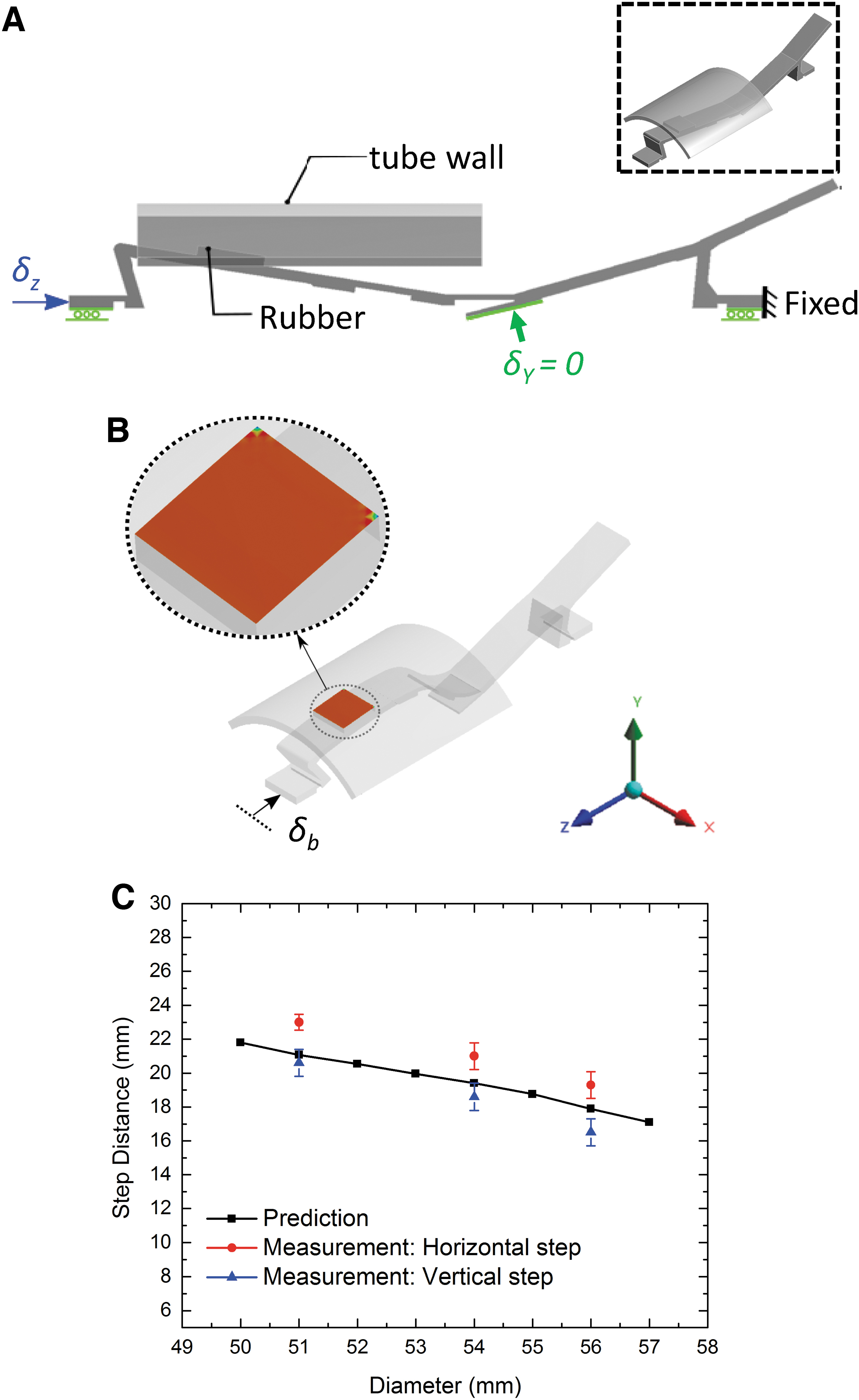
Step distance under different tube diameter (inflation: 0.7 s, deflation: 0.3 s).
Figure 6C compares the step distance between the simulations (horizontal only) and measurements. The measurements were performed in horizontal and vertical (upward) pipes at 0.7 s for inflation and 0.3 s for deflation, which allowed the ribbon to deform fully. An investigation of the results highlights the following observations: First, the robot works in pipes with a diameter from 50 to 57 mm (104–119% of the robot width), demonstrating good adaptability to the pipe diameter.
Second, the step distance drops by −17% as the pipe diameter increases. Third, the step distance in the vertical case is smaller than in the horizontal case (−10% and −13% for the 51- and 56-mm pipes, respectively). When the robot crawls upward in the vertical pipe, the gravity tends to pull it downward. Hence, at the moment of the switch between anchor points, as shown in Figure 2d, a slight backward motion occurs (δb increases), leading to a smaller step distance (δf decreases). Fourth, the simulations are generally consistent with the measurements with the values between horizontal and vertical cases. The underestimate of the step distance is due to the offset between the centerlines of the pipe and robot. The robot's centerline is slightly lower than the pipe's due to gravity, a factor not included in the model.
Existence of elbows
One chief challenge for in-pipe robots is how to move through elbows. We overcome this by adding two key features: the front cap and the rear-end friction structure (Fig. 1A; Supplementary Fig. S4A). The cap helps keep the robot located near the centerline of the pipe and allows it to follow the curvature of the elbow. Once the robot crawls halfway through the elbow, the rear end of the robot deviates from the pipe centerline as the robot tends to maintain a straight posture, resulting in friction too low to propel the robot forward. Thus, the friction structure is added and can help the robot anchor at the elbow (Supplementary Fig. S4B). Our robot can overcome the elbows using the same operational parameters without adding new control schemes with this modification.
As shown in Figure 7A and B, our robot can pass through a 90-degree sweep elbow and a 45-degree elbow. The dimensions of the elbows are shown in Supplementary Figure S4C. We also design a 1.35-m long U-shaped pipe to test the robot's adaptability (Fig. 6C). Our robot can crawl up, down, and through the elbows in a single run without changing parameters. However, our current robot cannot pass through 90-degree elbows. The McKibben actuator has a finite length and some bending stiffness; it does not adapt well to elbows larger than 90 degrees.

Photographs of the robot passing through different elbows.
Wet pipes
Another chief challenge for in-pipe robots is how to move in a wet pipe. Wet pipes that contain water or other liquids are common in today's pipeline systems and are difficult to inspect using conventional electrically driven in-pipe robots due to the slippery surfaces and risk of short circuits. To test the performance of our robot in wet pipes, we carry out experiments under two conditions—pipes partially and fully filled with water. We operate the robot at a period of 0.45 s for inflation and 0.15 s for deflation, which allows the robot to crawl at high speed up to 27 mm/s under dry conditions (Fig. 8A).

Comparison under different conditions at one period (inflation = 0.45 s, deflation = 0.15 s).
In wet pipes, the robot demonstrates robust operations, although its speed drops to 20 mm/s (−26%) and 10 mm/s (−63%) in the partially filled (Fig. 8B and Supplementary Movie S4) and fully filled case (Fig. 8C and Supplementary Movie S5), respectively. The speed reduction may be attributed to the following factors: First, small slips occur during crawling as the coefficient of static friction is smaller in the wet pipe. Second, the water pressure may apply a drag force on the robot, slow down its motion, and even reduce the actuator's contraction δc. Hence, the robot crawls much slower in the fully filled case (Fig. 8C).
Optimizing the periods of inflation and deflation for each condition may improve the performance. In addition, if the pneumatic system can provide enough pressure, the robot can even crawl in a high-pressure pipe. More importantly, the robot's structure allows the fluid to flow through without choking the pipe during operation.
Conclusions
We have demonstrated that the highly nonlinear buckling of elastic ribbons can be exploited to create strong traction with directional anisotropic friction forces that can be integrated with McKibben artificial muscles in soft robots to achieve repeatable, self-adaptive, and robust crawling in dry and wet pipes even with a single actuator. Compared with other soft in-pipe robots that require multiple segments and actuators, our present design is simpler yet more robust and achieves several key advancements:
(i) Using only one actuator and simple on/off control, the robot can crawl in horizontal and vertical pipes with elbows in a single run. (ii) The robot can crawl in dry and wet pipes—even fully filled with water. (iii) When fully compressed, the robot attains strong traction forces of 8.7-fold (pulling backward) and 2.6-fold (pulling forward) of its body weight. (iv) By optimizing the inflation and deflation durations, the robot can achieve a competitive crawling speed, for example, 33 mm/s or 22% of its body length. (v) Using the same operational parameters, the robot can crawl in pipes of different diameters (e.g., 104–119% of the width for the prototype robot), demonstrating good adaptability. Moreover, our elastic ribbons are fabricated by 3D printing without the cumbersome conventional molding process and feature special notches and inclined plates.
Mechanical instabilities triggered under uniaxial compression of a McKibben actuator are then exploited to create tailored 3D buckling shapes that propel the robot forward. Although our experiments were mainly conducted in pipes with a diameter of 51–57 mm, the proposed design concept is scalable and is promising at other length scales.
Finally, we note that our robot is pneumatically actuated using air transferred from an external pump through a hose. Real-world applications, however, require a stand-alone system that can function without a tether. In this case, the control circuit board, battery, miniature pump, and valve must be integrated into the robot. A successful example was recently reported by Rafsanjani et al. 45 —they developed an untethered pneumatically-driven kirigami-skinned soft crawler capable of untethered locomotion. They used a micropneumatic diaphragm pump and two 2- to 3-way miniature pneumatic solenoid valves. The maximum power of this pump was small (0.347 W) but was sufficient to drive their robot.
However, conventional McKibben actuator requires more power to drive, and thus, the capability of untethered actuation is challenging and is a good topic for future study. Another limitation of our current design is that the robot can only move forward. In normal operations, the robot moves out of the pipe through the pipe exit. However, if the robot needs to move out through the entrance, external forces must be applied to the air hose to pull it out. In this case, new features may be added to facilitate this process by minimizing the ribbon-pipe contact.
Footnotes
Acknowledgments
This work is supported by National Taiwan University and the Ministry of Science and Technology (MOST) of Taiwan. The authors thank Ya-Chen Hsu for the helpful discussion on snake locomotion.
Authors' Contributions
Y.L.: Conceptualization, data curation, formal analysis, investigation, methodology, validation. Y.-X.X.: Data curation, formal analysis, investigation, validation, visualization, writing—original draft. J.-Y.J.: Conceptualization, funding acquisition, methodology, project administration, resources, supervision, writing—review and editing.
Data Availability
The data are available upon request from the corresponding authors.
Author Disclosure Statement
The authors declare that they have no known competing financial interests or personal relationships that could have appeared to influence the work reported in this article.
Funding Information
This work is supported by National Taiwan University and the Ministry of Science and Technology (MOST) of Taiwan.

References
Supplementary Material
Please find the following supplemental material available below.
For Open Access articles published under a Creative Commons License, all supplemental material carries the same license as the article it is associated with.
For non-Open Access articles published, all supplemental material carries a non-exclusive license, and permission requests for re-use of supplemental material or any part of supplemental material shall be sent directly to the copyright owner as specified in the copyright notice associated with the article.
