
Abstract
Current aerial robots demonstrate limited interaction capabilities in unstructured environments when compared with their biological counterparts. Some examples include their inability to tolerate collisions and to successfully land or perch on objects of unknown shapes, sizes, and texture. Efforts to include compliance have introduced designs that incorporate external mechanical impact protection at the cost of reduced agility and flight time due to the added weight. In this work, we propose and develop a lightweight, inflatable, soft-bodied aerial robot (SoBAR) that can pneumatically vary its body stiffness to achieve intrinsic collision resilience. Unlike the conventional rigid aerial robots, SoBAR successfully demonstrates its ability to repeatedly endure and recover from collisions in various directions, not only limited to in-plane ones. Furthermore, we exploit its capabilities to demonstrate perching where the three-dimensional collision resilience helps in improving the perching success rates. We also augment SoBAR with a novel hybrid fabric-based bistable (HFB) grasper that can utilize impact energies to perform contact-reactive grasping through rapid shape conforming abilities. We exhaustively study and offer insights into the collision resilience, impact absorption, and manipulation capabilities of SoBAR with the HFB grasper. Finally, we compare the performance of conventional aerial robots with the SoBAR through collision characterizations, grasping identifications, and experimental validations of collision resilience and perching in various scenarios and on differently shaped objects.
Introduction
Aerial manipulation highlights the ability for aerial robots to perform manipulation or interaction tasks such as perching/grasping to widen their scope of applications. Perching, specifically, enhances the ability for aerial robots to save energy and maintain a vantage position for monitoring or surveillance,1,2 and the perching mechanism can also be exploited for performing dynamic grasping. Existing aerial robots coordinate perching mechanisms and flight dynamics to achieve this.2–4 Nature, however, calls attention to various physically intelligent features that can enhance the proficiency of dynamic aerial robot perching and grasping.5–7
Birds and bats enter a coordinated post-stall maneuver to maintain a constant rate of approach in combination with a high angle of attack.8–10 At impact, their feet clasp the irregular perch and their legs bend to absorb their momentum.11–13 Their feet also utilize a passive tendon locking mechanism, so no additional energy is wasted during perching. 14 Even smaller insects, such as flies, utilize a combination of collision and perching, and their compliant bodies help dampen the perching impact. 15
However, there is often a dissociation between controlled collision and dynamic perching in the existing design of aerial robots, as the rigid body structures (found on quadrotors and avian-inspired graspers) are not good at mitigating collision impact incurred during dynamic perching. Furthermore, current avian-inspired graspers are limited to perching on cylindrical-shaped structures,16–19 this is because of the lack of intrinsic softness in their fingers and joints. Recent work has started taking into account controlled collisions during dynamic perching,18–20 utilizing mechanisms to mitigate the impact during a more dynamic perching sequence.
For example, Roderick et al 19 utilized legs that bend (along with an avian-inspired grasper with claws), whereas Stewart et al 18 utilized a spring-based mechanism to absorb the robot's momentum resulting from perching impact. Kirchgeorg and Mintchev, 20 however, explored the use of an external protective exoskeleton, along with a high-friction, passive, hook-and-hang perching mechanism. These robots, however, do not extensively quantify their ability to mitigate the high impact in collision-based perching. They are also still limited by grasping targets with circular cross sections.
Along with dynamic perching, aerial robots also have to deal with unexpected interactions in obstacle-laden environments with poor visual conditions. Therefore, collisions are inevitable even with state-of-the-art collision avoidance and computer vision systems.21,22 With aerial robots, high-energy impacts or collisions can lead to structural damage or loss of control, resulting in crashes. While conventionally, researchers have avoided physical interactions,23,24 recently, researchers have developed collision-resilient aerial robots with compliant bodies to sustain collisions while remaining stable in the air and/or surviving structural damage after crashing25–29 or additional external protective structures.20,29–36
Soft robotics has emerged as a promising solution to approach the problem of collision resilience and safe perching.37–39 Compliant materials have been utilized to design soft or foldable wings,40–44 deformable rotors, 45 compliant joints and armatures,25,30,46–49 and compliant graspers or landing gears.50–58 These soft solutions for perching and grasping, however, are often limited by their load-bearing capabilities and slow grasping speeds. The former limits their ability to maintain a strong grasp on objects or carry meaningful payloads. Due to their limited grasping speeds, they resort to hovering closely or landing on the perch before grasping. They also sometimes require active actuation to maintain constant grasping or perching position, which reduces the overall system efficiency.
In this work, we develop a novel inflatable soft-bodied aerial robot (SoBAR) that can tolerate high-impact collisions with the environment in any direction, as shown in Figure 1A and D. SoBAR highlights a lightweight pneumatic frame capable of modulating its stiffness, for contact resilience and flight stability, as shown in Figure 1C. The process of setting up SoBAR takes ∼4 min, making it effortlessly portable, as highlighted in Figure 1F and Supplementary Video S1. Further capitalizing on the collision resilient frame, we introduce a passive dynamic hybrid fabric-based bistable (HFB) grasper design, which reacts to impact upon contact with the perching surface and enables manipulation abilities, as illustrated in Figure 1B and E.
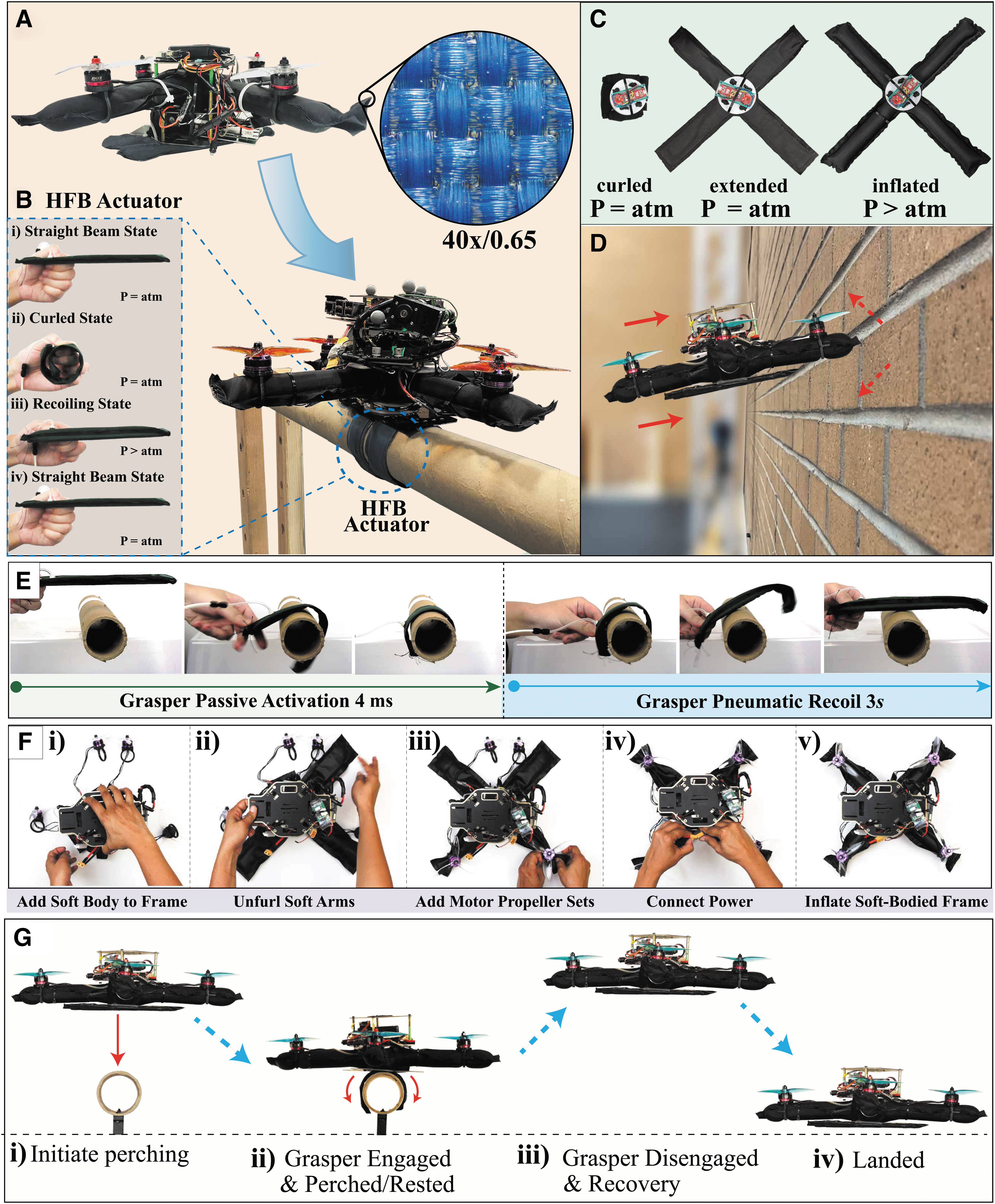
The overall operational scheme of SoBAR.
Utilizing a snap-through buckling instability in its passive design, the grasper absorbs the impact energy and uses it to transform into a continuum closed-form grasping shape in about 4 ms to adapt to various shapes and sizes of perching objects. An additional advantage of such design approach is that the passive grasper does not utilize any additional energy to maintain grasp and can be pneumatically retracted in less than 3 s, as shown in Figure 1E. Together, the soft-bodied frame and HFB grasper operate synergistically by mitigating the impact for successful dynamic perching on various objects, as shown in Supplementary Videos S5 and S7 and Figure 1G.
To the best of our knowledge, this is the first report of a multirotor aerial robot that utilizes an entirely soft body based on inflatable fabrics to modulate its stiffness and absorb impacts. In summary, this work contributes to:
A new class of aerial robot frames based on inflatable high-strength fabrics, capable of effectively absorbing impact forces from collisions and contact-based perching. A new class of a lightweight gripper for aerial robots based on the combination of inflatable high-strength fabrics and a bistable mechanism, which is capable of providing passively activated dynamic perching on objects of unknown shape and size. Modeling and analysis of both, the developed soft aerial robot and the bistable grasper, for developing planning and control strategies.
Materials and Methods
Design of soft-bodied structure
We opted for a standard “ × ” or “+” configuration for designing SoBARs pneumatic frame to benchmark the system's mechanical resilience in one arm or two arm collisions. We designed SoBARs frame to be geometrically similar to DJI F450's standard rigid frame (319 × 319 mm), for comparison in collision tests. SoBARs and DJI's frames weigh 10 and 120 g, respectively.
To develop the soft-bodied frame, we took inspiration from the lightweight, thin-walled, hollow pneumatic bones that are found in bird wings.59,60 Combining this idea with our previous work on soft fabric-based actuators,61–63 we chose to evoke a soft-bodied structure based on thin-walled, soft inflatable fabric beams. Such pneumatically driven structures are shown to be mechanically resilient to external interactions and can absorb impact-induced energies. These characteristics enable SoBAR to handle high-speed collisions, collision-based perching, and emergency landings.
Additionally, by having a collision-safe air frame eliminates the need for a cage-like structure around the aerial robot in applications where no humans are present, thus making the design compact and efficient. The intrinsically soft platform we designed can also vary in stiffness through pneumatic activation. Figure 1C and F shows that at zero internal pressure, the frame is completely collapsible and each arm can compress from 20.5 to 3 cm, a reduction in length of 85% (also shown in Supplementary Video S1). For flight, the frame is inflated to its maximum stiffness to reduce undesired oscillations, instabilities, or slow flight maneuver responses. The SoBAR frame can absorb impact through deformation, which extends the impact time with the perching objects to support the collision-based passive perching maneuver with the HFB grasper, as shown in Figure 1A. Fabrication of the SoBARs frame is detailed in Figure 2A and Supplementary Appendix A.

The manufacturing process of SoBAR and the HFB actuators.
Design of the HFB grasper
The HFB perching structure is designed with a thermoplastic polyurethane-coated nylon fabric external structure encasing preformed bistable metal steels, capable of converting high-impact energy and instantly reacting to the contact, to go from a straight beam to a rapidly curling state, as shown in Figure 1B. Each perching structure is made of multiple HFB actuators placed in possible perching orientations, as shown in Figure 2B and 2A(iv).
The design combines the energy storage nature of deformable spring steels and fabric-based actuators. The bistable spring steel, when activated, leads to power amplification and rapid curling movements that are highly desired for grasping. Furthermore, after perching, no further mechanical activation is required. To release it from its perched state, the inflatable fabric-based actuator layer allows the system to quickly recoil, to its initial straight beam state, as shown in Figure 1B(iv) and Supplementary Video S2. In this state, the grasper can also be utilized as landing skids. Along with its soft-bodied frame, the robot is capable of safe emergency landing situations, as shown in Figure 1G(iv). Fabrication of the HFB grasper is detailed in Supplementary Appendix A.
Hardware overview
SoBARs chassis hosts the flight controller, power module, and high-level companion computer, as shown in Figure 3. The flight controller monitors and controls the internal pressure of SoBARs body and the HFB grasper, by utilizing analog pressure sensors and an onboard micro diaphragm pump. The specific hardware and electronics details are further documented in Supplementary Appendix B. Before flight, motor propeller pairs are aligned and the flight controller sensors with the air frame are calibrated through QGroundControl. The experimental setups utilized in this work, including the universal tensile testing machine, the high-speed camera, high-G accelerometer, and motion capture system, are detailed in Supplementary Appendix C.
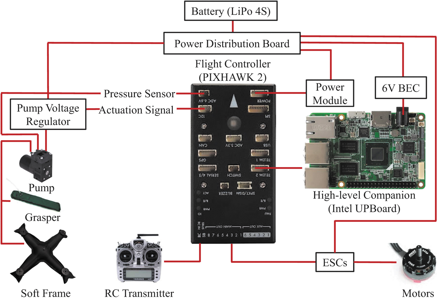
Electronics diagram of SoBAR. On the right part of the diagram, all the necessary components to achieve flight are illustrated. On the left part of the diagram, the proposed electropneumatic components for the soft frame and perching grasper are shown.
Modeling and control of SoBAR
As shown in Figure 4, the rotor thrust is significant enough to introduce slight deflection of the soft arms affecting in this way net thrust and SoBARs flight performance. To address this issue, we derive a model for the thrust loss coefficient as a function of the arm deflection angle.

Modeling arm deflection (
As noted from our experiments, discussed in detail in the Maximum Bending Deflection section, the maximum beam deflection at 207 kPa was noted to be less than 10°. Also for inflatable beams without wrinkles, we assume that the plane sections remain plane, that is, there are no significant shear or torsional stresses relative to the bending (axial) stresses. Based on these assumptions, we employ the Euler–Bernoulli beam theory64,65 to model the beam deflection as follows:
where l, Fi, and I are the arm length, thrust produced by the
Denoting the inertial reference frame by
where fi denotes the effective thrust of the  , which are related to the effective

where d and
The rigid body equations for SoBAR are given by:
where the hat map transforms a vector into its equivalent matrix to represent cross product as a matrix multiplication. Equations (4a) and (4b) describe the translational dynamics, whereas Equations (4c) and (4d) are used to describe the rotational dynamics of any quadrotor system and are standard nonlinear quadrotor dynamic equations in the SE(3) space. 66
A proportional controller for position and a proportional-integral-derivative controller for velocity structure for the low-level position control loop with a geometric controller 66 for the attitude control loop is employed for SoBARs tracking control. In free flight and near-hover condition (when there is no external physical force acting on the drone), the beam deflection gives rise to drift forces in the horizontal plane due to the residuals of the motor thrust's horizontal components. The gains of the controller are tuned via multiple experimental trials such that the pitch and roll gains are able to overcome the drift forces and maintain a stable hover condition, as documented in Supplementary Appendix K.
Trajectory planning for autonomous perching
The perching maneuver consists of multiple trajectories, which are described in this section. First, SoBAR approaches the target location and localizes itself to hover 30 cm above it (further details are given in Supplementary Appendix D). Once the position error is within the predefined tolerance, SoBAR initiates the descent trajectory. The reference trajectory for the descent consists of only position setpoints. When the position errors with respect to the target perch location is ∼0, the grasper hits the target and activates to initiate the high-impact dynamic perching. After this event, as soon as the position and velocity errors are reduced below a user-defined tolerance, the propellers are turned off to remain perched. In this article, a manual recovery is then performed by pneumatically disengaging the grasper before the takeoff and landing sequence. A block diagram for autonomous perching with SoBAR is given in Figure 5 with the perching strategy highlighted in the orange subblock.

The complete closed-loop control pipeline of SoBAR for the perching task. The green blocks show the computation performed on the flight controller. The high-level companion computer is used to relay the position and orientation information of SoBAR from the indoor positioning system to the flight controller. The perching strategy, shown in the orange block, represents the state machine during an autonomous perching task. Mathematical conditions represent event-triggered transitions while the clock symbol represents the time-triggered ones. Here, xh refers to the hover target location for SoBAR directly above the perching target before initiating the descent. After the errors in position are within a tolerance region denoted by
Results
Grasper evaluation
To characterize the performance of the HFB grasper, we first evaluated each HFB actuator for its tip force, activation force, and activation and recoil time. These experiments are detailed in Supplementary Appendix E. From the tests, we decided to utilize a triple spring steel set that generates a grasping force of 200 N, tip force of 0.55 N, activates within 4 ms, and pneumatically recoils within 3 s with a minimum input pressure of 83 kPa. From the activation force tests, we were able to approximate its desired impact velocity. With an impact time of ∼0.1 s (captured by the 500-fps high-speed camera), the triple spring steel set leads to a minimum approach velocity of 2.4 m/s, which corresponds to a free-fall drop height of ∼30 cm. This insight is effectively employed to demonstrate successful perching as shown in the Perching with SoBAR section.
We then designed the experiments with universal testing machine (UTM) for evaluating the grasping force of the multifingered grasper for perching. We tested the maximum grasping force for the two- and three-fingered actuator configurations, as shown in Figure 6. For each configuration, experiments were conducted on three cylinder diameters (55, 80 and 115 mm), chosen based on various perch sizes of interests. The graspers were fixed in place, in a horizontal position, whereas the cylinders were pulled upward at a rate of 8 mm/s. As soon as slip was detected, the grasping force was recorded, as shown in Figure 6. The average value of the maximum grasping force is calculated over five trials for each configuration. Further details of the slip detection criteria are described in Supplementary Appendix L.

Grasping force characterization of different grasper configurations (two- and three-fingered graspers) and three perch diameters. The two-fingered grasper was not able to successfully grasp the largest ø = 115 mm perch.
For the two-fingered grasper, the grasping capacity is observed as 66.58 ± 7.39 and 4.44 ± 1.02 N for the 55 and 80 mm diameter cylinders, respectively. For the three-fingered grasper, the grasping force on the 55, 80, and 115 mm diameter cylinders is 176.43 ± 12.46, 85.4 ± 5.55, and 12.06 ± 1.53 N, respectively. We notice that both grasper configurations struggle to maintain grasp with the 115 mm diameter cylinder because they are not able to maintain an envelope grasp around it.
To study the grasping force for objects that do not conform to the HFB graspers' workspace, we perform a static wrench analysis detailed in Supplementary Appendix F. With objects within its grasp radius, the grasper has a higher chance of resisting the external wrench to perform a successful grasp.
We finally demonstrate the improved grasping ability of the HFB grasper by comparing its high power-to-weight ratio of 600 and 1173 N/kg for the two-fingered and three-fingered version respectively, with the many grippers available in the literature 2 as described in Supplementary Appendix I and Supplementary Table S3.
Evaluation of soft-bodied frame
Maximum bending deflection
A bending test was performed to calculate the maximum beam deflection due to the motor thrust at different internal pressures. The UTM was used to simulate the motor thrust, as shown in Figure 7A. With the chosen motor-propeller pair, a maximum thrust of 10 N was generated by each motor, and hence, the UTM was programmed to pull one end of the beam until it reached 10 N. The deflection at 10 N was averaged across 10 trials and denoted in Figure 7A. Approximating the arm as a circular cross section for the second moment of area such that

Collision drop tests
To test the collision resilience of SoBARs soft-bodied frame, we performed comparative drop tests with a rigid DJI F450 frame and recorded the impact times and peak accelerations of the frames in “+” and “ × ” configurations. We also evaluated the drops at two different set heights of 25 and 50 cm corresponding to two different impact velocities of 2.21 and 3.1 m/s, respectively. For each configuration, five trials were performed and the impact times captured with a high-speed camera, shown in Supplementary Video S2.
The results are shown as the bar plots in Figure 8A and B and summarized in Table 1. Figure 8C and D represents the experimental setup utilized and is further detailed in Supplementary Appendix C. Slow motion frame captures of a single drop test for the “+” and “ × ” configurations of the soft-bodied frame at 138 kPa are shown in Figure 8C(i) and (ii) and also compared side by side in Supplementary Video S3. It is also similarly displayed for the rigid frame in Figure 8D(i) and (ii). The rest of the drop tests is presented in Supplementary Appendix H.

Collision drop tests at drop heights 25 and 50 cm for
Impact Times for Soft-Bodied Aerial Robot and the Rigid DJI F450 Frame in Various Configurations
For the rigid frame, the impact time for the “ × ” and “+” configurations was ∼22 and 8 ms. The maximum peak acceleration experienced by the frame was ∼390 m/s 2 , corresponding to a very high peak impact force of 430N, in the “+” configuration and ∼404 m/s 2 corresponding to a peak impact force of 449 N in the “ × ” configuration. This is depicted in the bar plots, as seen for the five different trials, in Figure 8A. These high impact forces were experienced by the chassis because the rigid frame does not deform, transmitting the entire impact force to the main body.
We hypothesize that the large variance in impact force readings is due to the impact times being so miniscule, that, at the current sampling rate of the sensor (maximum of 1 kHz), it would sometimes miss the peak acceleration reading. However, the soft-bodied frame of SoBAR generated deformation upon collision, which led to much longer impact time (10 × in both configurations) compared with the rigid frame. The soft-bodied frame is capable of extending the contact impact time through its body deformation, which leads to lower impact force, as shown in Figure 8A and B.
Between the “+” and “ × ” configurations of the soft-bodied frame, we notice that the “+” configuration experiences lower impact forces overall. Although the “ × ” configuration highlights longer impact times, as shown in Table 1, its arms mitigate the impact by splitting outward, which can be less ideal for collision mitigation. For example, Figure 8A highlights the experiment with the SoBAR frame that experienced the largest recorded impact forces at 138 kPa and 50 cm, also captured in Figure 8C(ii). We notice that at 120 ms, the arms have completely split outward, causing the chassis to impact the ground, thus leading to high impact forces.
This behavior is even worse with the 69 kPa frame when dropped at 50 cm, saturating the onboard accelerometer. The slow motion capture of this test is highlighted in Supplementary Figure S4. This behavior is analogous to Euler springs where beyond the maximum compression distance, the entire impact force is transmitted to the chassis. However, by increasing the internal pressure of 207 kPa, even at the 50 cm drop, the “ × ” configuration is able to successfully mitigate the impact without the main chassis contacting the ground.
We further compare the collision resilience ability of SoBAR with the many available collision resilient aerial robots in Supplementary Appendix J and Supplementary Table S5.
Since indoor aerial robots are prone to collisions with impact velocities up to 2 m/s, we chose to utilize the “+” configuration at 207 kPa, to maximize the collision mitigation ability and minimum thrust loss (discussed in the Maximum Bending Deflection section) for the collision and flight demonstrations with SoBAR, in the Collision Demonstration section and the Real-Time Experiments Section.
Collision demonstration
To verify SoBARs collision performance, we carried out a series of experiments where the drone took off and approached the target setpoint without the knowledge of the wall. Upon collision, it recovered and the collision trajectory was recorded in slow motion, as shown in Figure 8E. It is observed that due to the deformation of the soft body, low rebound velocities in the range of 1.5 m/s corresponding to high collision velocities of up to 2 m/s are achieved. These low rebound velocities help in post-collision recovery control without the need for complex collision characterization. 27 The head-on collision performance is highlighted in Supplementary Video S4. For the conventional rigid chassis, the rebound velocities are significantly higher, as observed through our experimental tests that were also captured with the high speed camera and shown in Supplementary Video S2 and Supplementary Appendix H, leading to complex collision characterization and recovery control. 27
Perching with SoBAR
Real-time experiments
The z position trajectory of SoBAR for real-time perching is shown in Figure 9A and B. This coordinate was chosen to mark the various phases of the maneuver, as shown in Figure 9A and B. We demonstrate SoBARs perching ability on a cylindrical and rectangular cross-sectioned objects, also highlighted in Supplementary Video S5. Initially, SoBAR approaches and hovers above the target location, which is obtained by placing an infrared marker on the perching object. This hover phase is marked where the height is oscillating due to small errors in the tracking control.

Takeoff, perch, recover, and land sequence of SoBAR for one of the three successful trials.
Once the position errors fall within the preset bound, the free-fall descent is initiated for perching, this is shown by the steep slope of the z position trajectory. After the successful perch, SoBAR rests for a user-defined wait time and then performs a manual recovery and landing sequence. We conducted three autonomous perching experiments for two different objects and the perching results for one run on each object are shown in Figure 9A and B, respectively. As previously mentioned, since the object radius is within the maximum grasp radius, we have significantly high success rates (four of five times). Figure 9C and D highlights snapshots of the experimental setup and the real-time perching, recovery, and landing maneuvers.
Perching with rigid versus soft-bodied frame
We compared the perching ability between SoBAR and rigid DJI frames, mounted with the HFB grasper, dropped from a height of 25 cm onto a circular perch, as shown in Figure 9E and F and Supplementary Video S6. For the rigid frame, we notice that the impact times are significantly smaller (2–4 ms) leading to higher impact forces. These forces are too large to not only activate the grasper but also cause a rebound motion, as shown in Figure 9E(ii) and (iii), which causes the system to bounce off the perch, before the grasper can successfully engage, as shown in Figure 9F(iii). As the grasper is already partially activated, the friction on the fingers helps the rigid frame from completely falling off. However, because of the uneven application of wrench forces, there is noticeable slippage, shown in Figure 9E(iv), until enough contact is reached in Figure 9E(v). This leads to unpredictable final configurations, as shown in Figure 9E(v) (roll angle almost 90°), which can be difficult to recover from. The success rate for this case scenario was one of five.
We notice that upon impact SoBARs frame undergoes deformation thus increasing the impact duration, as shown in Figure 9F(iii–v). This allows contact with the perch for a longer time, leading to successful engagement of the HFB grasper. SoBAR was able to successfully perch four of five times. This highlights how the deformable body improves the perching capabilities in comparison to the rigid frame and aids in the application of the wrench forces, without explicit grasp hull computations and results in a robust grasp during the perching task.
We perform further characterization of the grasping performance by running situational experiments with a rigid frame, rigid frame with additional mechanical damping, and the SoBAR frame at various internal pressures as described in Supplementary Appendix G1 and Supplementary Video S6. The success rates are documented in Supplementary Table S2. In all cases, it can be verified that the SoBAR frame can successfully engage the gripper and provide high success rates.
We also extend the drop tests of SoBAR to other real-world objects, such as a hard-hat helmet (22 cm diameter), edge of a ladder (4 × 2 cm), a rock (6.5–8 cm width, 23 cm height), a tree branch (7.3 cm diameter), a joint of a UR-5 robot arm (10 cm diameter), and a sanitizer stand (13 × 18 × 10 cm), highlighting the capabilities of the system to perch onto objects with different shapes and sizes, shown in Supplementary Figure S2 of Supplementary Appendix G2 and Supplementary Video S7.
We characterize the stability of the perch with SoBAR and the HFB grasper against various other state-of-the-art perching aerial robots in Supplementary Appendix I and Supplementary Table S4. We note that SoBAR is capable of perching on irregular objects, cylindrical objects, and also on planar surfaces when compared with other proposed avian-inspired graspers.
Finally, we demonstrate in Supplementary Video S8, how SoBAR can successfully perch while undergoing collisions from a nearby wall. The rigid frame with or without the damper failed in all simultaneous wall-collision tests during perching. The SoBAR frame, at higher stiffness (at internal pressure 103 and 138 kPa), was not successful on every trial. But, the SoBAR frame at 69 kPa allowed deformation of its arm upon impact absorbing the collision forces and simultaneous perching successfully. Further details about the trial success rates are documented in Supplementary Table S7 of Supplementary Appendix M.
Conclusions
Summary
This article presented the design, development, and evaluation of an untethered, lightweight, robust, and compliant fabric SoBAR composed of a soft-bodied frame and HFB grasper. The vision of this work was geared toward addressing two previously disconnected capabilities in aerial robots, namely impact mitigation and dynamic perching, through the co-development of the body and grasper of the aerial robot.
The SoBAR frame and the HFB grasper operate synergistically to perform high-speed, high-impact, and dynamic collision-based perching. We observed that the SoBAR had a perching success rate of four of five times on objects within the grasp radius of the HFB grasper during our experiments. Furthermore, we also demonstrate how SoBAR can successfully perch while undergoing a wall-collision, by exploiting its deformable arms and variable stiffness.
Limitations and future directions
As with every novel design, the current SoBAR comes with some observed limitations, which are open challenges to future iterations for improvement. To start with, we experienced a beam deflection of ∼5.80° at 207 kPa, which led to slight thrust loss (maximum loss coefficient of 0.95 at 69 kPa) and force residuals in the body
In the future, we aim to maximize the energy efficiency of the soft body by optimizing its design for improved stiffness at various internal pressures. This can be achieved through varying the design of its cross section, 62 including internal soft truss structures, and/or developing a rigid-soft hybrid frame. The currently utilized Euler beam theory for calculating the thrust coefficients is less accurate in the presence of shear stresses, at lower internal pressures. To address this, we will explore detailed modeling of the pneumatic beam and the corresponding thrust vectoring, via machine learning methods for developing model-based low-level flight controllers.
Similarly, for the HFB grasper, although we observed that it was adaptable to many irregular shapes, we feel that there still is room for design improvements. Currently, the HFB graspers are mounted against a flat plate, which slightly limits their bending range. This therefore reduces the maximum surface contact between the grasper and the perching object, as the region of the grasper mounted to the flat plate cannot bend or curl. We anticipate that by redesigning the grasper mount to fully utilize its continuum nature, its entire grasping surface area would be utilized more effectively. Furthermore, through exploration of different bistable materials with varying thicknesses has the potential in improving the torsional stability of the grasper. The above design improvements combined with prestrained adaptations of parts of the grasper can further increase its grasping force. Finally, exploration in the addition of adaptive surface structures, such as microspines or microhooks, could increase its friction coefficient and thus grasping performance.
During the collision resilience validation in the body
For immediate future work, we seek to demonstrate real-life highly dynamic autonomous perching with SoBAR by visually detecting suitable perches. Aggressive trajectory planning and robust control strategies will also be explored that can enable approaching objects at different angles and heights in an obstacle laden environment. The discussed future efforts have the potential to enable battery recharging techniques for prolonged outdoor monitoring, as well as search and data collection missions.
Finally, our work lays a stepping stone to design soft and compliant aerial robots where the chassis is utilized for achieving intrinsic safety and collision resilience. We hope that the insights from our work shall inspire novel bioinspired designs for soft reconfigurable and conformable aerial robots to obtain various functionalities such as whole-body perching and grasping.
Footnotes
Acknowledgments
We would like to thank Saivimal Sridar, Weijia Tao, YiZhuang Garrad, Aravind Adith, and Sunny Amatya for their help with fabrication, setting up video recordings, setting up the UR5 tests, and helpful suggestions during the ideation and article editing process.
Author Disclosure Statement
No competing financial interests exist.
Funding Information
No funding was received for this work.
References
Supplementary Material
Please find the following supplemental material available below.
For Open Access articles published under a Creative Commons License, all supplemental material carries the same license as the article it is associated with.
For non-Open Access articles published, all supplemental material carries a non-exclusive license, and permission requests for re-use of supplemental material or any part of supplemental material shall be sent directly to the copyright owner as specified in the copyright notice associated with the article.