




Abstract
Despite the exponentially expanding capabilities of robotic systems with the introduction of soft robotics, the lack of practical considerations in designing and integrating soft robotic components hinders the widespread application of newly developed technology in real life. This study investigates the development and performance evaluation of soft-rigid hybrid (SRH) robotic systems employing multilayered bellow-shaped soft pneumatic actuators (MBSPAs) to overcome the common challenges exclusively exhibited in soft robotics. Specifically, we introduce a unique SRH revolute joint enabled by a single thermoplastic polyurethane-MBSPA and rigid components to tackle the limitations of existing soft pneumatic actuators (SPAs), such as restricted payload capacity, vulnerability to external damages, and lack of resilience against outdoor environment. The proposed SRH system entails rigid components encapsulating to protect the MBSPA throughout the entirety of the desired range of motion, and demonstrates improved displacement efficiency, force output, and resilience against external loads. The rigid components also help to stabilize the axis of motion, fostering high durability and repeatable motion. We also extend this concept to a one-degree of freedom SRH prismatic joint. Finite element method modeling is used to estimate the general actuator performance, facilitating the design of MBSPA with limited material information and bypassing trial and error. The wider application of this research targets delicate object handling in industries such as agriculture, encouraging safe and efficient automated harvesting. The article includes thorough actuator performance characterization including displacement, frequency response, durability with life cycle testing up to 25,000 cycles, force output, stiffness, and power density. Performance comparisons with other SPA are provided. A proof of concept 3-point gripper enabled by the proposed SRH joints is capable of gripping objects of various sizes and shapes, with detailed workspace analysis and demonstration showing the gripper’s versatility. The SRH system presented here lays a robust foundation for the ongoing advancement of soft robotic technology toward real-life applications, unveiling the potential for a future in which robots operate efficiently in the targeted applications, aiming to integrate seamlessly into workflows with human workers.
Introduction
With the advent of soft robotics, the range of complex tasks that can be performed by robotic systems has expanded dramatically over the past decade. 1 The compliant nature of soft materials offers an intrinsic benefit for soft robotic systems, especially in applications requiring compliance such as safe physical human-robot interaction, exploration of unstructured environments, and handling of delicate objects.2,3
Leveraging the ability of soft actuators to safely manipulate delicate objects via conforming to irregular shapes and sizes, soft manipulators such as soft grippers have been developing quickly toward delicate object handling. 4 One prominent direction of soft grippers is in food and agriculture industry applications such as harvesting of berries and other delicate fruits, in which the compliant soft grippers prove the potential for automated harvesting without damaging the products to preserve their commercial viability. 5 In fact, soft robotics research toward fruit harvesting is becoming more important than ever. With the rising demand for food products confronted by the increasing labor shortage issues, producers are now gearing toward automated harvesting options. 6
There exist numerous types of soft grippers made available with the rising efforts of soft robotics research over the years. While the mechanisms and the gripper methodologies are dependent on the functionality required in specific applications, soft pneumatic actuators (SPA) are one of the most commonly reported soft grippers.7,8 SPAs fundamentally have low inertia, fast response, a wide range of force output, and can be fabricated easily at low cost, hence are favorable for iterative research purposes.9,10 With the ability of SPAs to vary stiffness and its capability to provide compliant gripping for the safe handling of delicate objects, many researchers adopted SPAs as end-effectors in harvesting applications. 4 However, soft robotic systems comprised solely of SPAs rely on predefined trajectories, have limited payload capabilities, suffer from oscillations, and lack structural support.11,12 Moreover, SPAs are susceptible to cuts and punctures, and hence extremely vulnerable to any sharp objects. In applications such as berry harvesting, environmental factors such as thorns, sharp branches, and ultraviolet (UV) radiation puts the practicality of soft grippers at risk. For soft robotic systems to deliver a valid impact to the targeted industry, practical considerations must be incorporated. 13
In efforts to overcome the disadvantages of soft pneumatic grippers, the incorporation of rigid structural components1,14 has been proven to be effective in providing improved performances and has opened doors for new types of soft-rigid hybrid (SRH) embodiments.15,16 One class of SRH systems incorporates mold-casted pneumatic network (PneuNet) actuators (MCPNA) with rigid components, which has achieved increased tip force output, allowing for a wider range of stiffness variations, and shortened actuation times.17–19 However, even though the fabrication of this MCPNA-rigid hybrid system is straightforward and repeatable,20,21 MCPNAs have fixed bulky volumes. Their bulky nature fundamentally limits the addition of rigid components without affecting form factor, especially when trying to provide an enclosure or protection elements to the soft actuators, completely exposing them to harsh external environments.
Another class of SRH systems uses blow-molded bellow-type SPA as joint actuators driving the linear and/or angular movements of the rigid linkages.22,23 Often incorporated with rigid hinges to attain a fixed center of rotation, 24 the kinematic trajectory is always consistent and hence repeatable. 25 However, blow-molded bellow actuators require high pressure input to achieve practically relevant displacements and hence energy inefficient. 26 The nature of the fabrication method also results in a fixed bulky volume, even at the fully retracted state using vacuum pressure.
As an alternative approach to blow-molding, multilayered bellow-shaped SPA (MBSPA) use a 2D manufacturing approach using thin textiles, polymer films, and thermal adhesives.27–29 The resultant MBSPAs have minimal thickness when fully retracted, provide an excellent retraction-expansion ratio, and can be easily stacked on top of one another. These features make them well-suited to be integrated into small spaces and less susceptible to spatial constraints. 28 SRH embodiments with MBSPAs would allow the system to be modular and help to attain dexterous manipulation.16,30 Although there had been investigations on SRH structure using MBSPA as soft joints driving the attached rigid links, 30 methods to use only one single MBSPA to achieve motions equivalent to a revolute joint of a rigid robot have not yet been explored. 16 The current existing methods require 2 or more MBSPAs to provide multiple degrees of freedom (DOF) such as roll and pitch motion,16,31 in which the rotation axes are often unconfined with a lack of rigid reinforcements.28,29 Moreover, limited information is available in terms of the durability, performance repeatability, dynamic response of these MBSPA-enabled SRH structure, and practical methods to provide protection to the MBSPA.
In this study, we propose a novel method for attaining a 1-DOF SRH revolute joint enabled by one single MBSPA comprised of thermoplastic polyurethane (TPU-MBSPA), targeted for building a novel SRH gripper toward delicate object handling applications such as berry harvesting. To contribute further, we extend this study to investigate a 1-DOF SRH prismatic joint. Built with rigid components encapsulating the MBSPA, the proposed SRH system allows for more efficient displacement characteristics, improved force output, and better resilience against external loads compared to similar types of SRH configurations. Moreover, the rigid components fixate the axis of motion, allowing the SRH joints to be highly durable and have repeatable motion.
In the remainder of this article, we first explore the fabrication methods of MBSPAs and the material characterization of the thermoplastic polyurethane (TPU) used in this study, followed by a simplified investigation of the constitutive continuum mechanics model for the generic finite element method (FEM) modeling of the TPU-MBSPA without the rigid components. Upon introduction of SRH configuration, investigation, and extensive characterization of the SRH prismatic and revolute joints, we compare the performance outcomes of the SRH joints to similar configurations. We then present the proof of concept 3-point gripper, enabled via SRH revolute joints, for delicate object handling applications.
MSPBA Actuators
TPU-MBSPA fabrication
MBSPAs are fabricated using the 2D layered manufacturing approach. 29 Many previous works had already investigated several varied methods for fabricating MBSPA, utilizing different materials and alignment methods.27,32,33 Typically, TPU adhesive films are used to provide thermal adhesion between layers of other materials. In this study, we fabricate TPU-based MBSPA using the thermal adhesion properties of the 0.152 mm-thick TPU adhesive films (3916 Adhesive Film; Bemis™) to function both as the continuously deforming structural actuation layer and as the self-adhesive layer 34 Although the fabrication process is very similar to the thermoplastic elastomer stacked balloon actuators,27,28 utilization of thermal adhesive TPU films allows lower temperature (110 °C) and shorter thermal bonding duration (30 s per thermal bonding), despite having larger material thickness (i.e., 0.152 mm vs <0.05 mm32,33)
The TPU-MBSPA consists of three layers: TPU layer, insert layer, and separation layer as shown in Figure 1. The 16 mm diameter insert layer is sandwiched between two 20 mm diameter TPU layers creating an inflating chamber. The separation layer is used to control the area of thermal adhesion from one pouch to another and is removed after the bonding. It is critical that the separation and insert layers do not thermally bond with the TPU layer. Although polydimethylsiloxane (PDMS) membrane, Teflon, non-stick paper, polyvinyl alcohol, or other thermoset materials 34 are good choices for both the insertion and separation layers, Teflon-coated non-stick paper was chosen in this study because it can be removed easily by ripping it apart. 34 Additional details and key variables in fabricating TPU-MBSPA are included in Supplementary Data S1, Section 1.

Fabrication process of TPU-MBSPA.
Material characterization
FEM is commonly used to estimate the generic actuator performance and to optimize actuator design without the need for deriving the explicit analytical model. 35 However, material-specific properties required for hyperelastic modeling are often not readily available from the literature, with the exception of the widely used materials. 9
The material coefficients in hyperelastic models are typically determined using the following test modes: uniaxial tension, equibiaxial tension, pure shear via planar tension, and volumetric deformations if the material is compressible. Hyperelastic materials are generally assumed to be incompressible, 35 in which the volumetric deformations are neglected. Previous work has also validated this assumption for a similar TPU material. 36 Though equibiaxial tensile test is recommended for the full description of deformation modes and improved accuracy of FEM results, they require specialized testing equipment not readily available. As such, studies often used uniaxial tension and pure shear test data, 37 and in most cases, used only the uniaxial tensile test data and yet obtained accurate estimation.35,36,38 Therefore, in this study, hyperelastic FEM model is constructed using only the uniaxial tensile test results.
The uniaxial tensile test of the 0.152 mm-thick TPU was performed as per the American Society for Testing and Materials (ASTM) D882 standard 39 with the maximum displacement of 1 m (C43-104E; MTS Systems Corp), resulting an engineering strain of over 500 %. Note that this ASTM standard is akin to the International Organization for Standardization (ISO) 527 standard, though not technically equivalent. 40 As shown in Figure 2A, the TPU tensile specimen did not fail despite a large strain of over 500 %.

Material characterization.
The effects of heat pressing TPU to its glue line temperature of 110 °C on uniaxial tensile response were also investigated. The stress–strain curves obtained from the samples closely matched those of the original material, with minimal deviation. This implies that the material properties will not be significantly affected by the elevated temperatures in outdoor environments. In addition, certain TPU materials and their variations are reported to possess high anisotropy, which could cause large errors when using simple FEM modeling based only on uniaxial test information41,42 For the accurate simulation of anisotropic materials, additional material test modes such as equibiaxial tensile tests are critical. 43 Therefore, the verification of material isotropy is essential to justify the presented approach of utilizing only uniaxial tensile tests for formulating hyperelastic material models. The TPU films were found to be isotropic by performing uniaxial test on the samples prepared from TPU films in mutually orthogonal directions. To further investigate the isotropy, scanning electron microscope (SEM) was used to obtain a topographic image (Fig. 2B) via secondary electron detector. The pores are randomly distributed and independent of specific directions further supporting the isotropic assumption. This verification of material isotropy allows us to greatly simplify the material test modes required for a generous estimation of the material behavior through material modeling and FEM simulation.
Hyperelastic model and FEM simulation
Many hyperelastic models used in soft materials are phenomenological models based on material behavior and can be derived from two hyperelastic models, which are polynomial form (Equ. 3) and Ogden model (Equ. 4). The polynomial form represents strain energy density function by one or more of the three strain tensor invariants which is expressed as
The uniaxial tension test data as well as other characteristics of the TPU material were input into Abaqus (Abaqus SIMULIA™; Dassault Systèmes SE). The built-in software was used to fit the experimental data with the constitutive hyperelastic models (Fig. 3A). The material coefficients for the deviatoric and volumetric terms of corresponding constitutive model were summarized in Table 1. Third order Ogden model resulted in the best fit with stability over all the strain range with small fitting errors, which then the TPU-MBSPA comprised of 5 actuation layers was simulated using the third order Ogden model and visually compared with the fabricated TPU-MBSPA as shown in Figure 3B. Based on the simulation information, the maximum strain of 87 % was observed at 40 kPa pressure input. Note that in this study, FEM is only used for the purpose of generating a generous estimation of the general actuator performance with limited material information, to avoid using trials-and-errors approach in designing MBSPA. This method is valid given that the material has been verified to be isotropic and that the operating strain range is low relative to the maximum strain achievable by the material. Should the desired application require further deformation of the material and hence operate at high strain ranges, or if the material is anisotropic, additional test modes may be necessary to acquire an accurate estimation of the actuator performance.

Behavior of the TPU material as expected from the simulation model.
Summary of Hyperelastic Constitutive Models and Their Material Coefficients, Stability Information, and Fitting Error (Least Squares), as Attained from Abaqus
The quasi-static linear displacement data of the 5-layered TPU-MBSPA along with the displacement results from the simulation were shown in Figure 3C. Even though the Ogden models are not preferable in modeling with limited material test data, both the third order Ogden model and the Mooney–Rivlin model resulted in solid estimation of the TPU-MBSPA expansion behavior. Despite the Mooney–Rivlin model had a fitting error of 16.2 when simulating the large deformation of TPU throughout its entire strain range exceeding 500 %, it was still able to provide a good estimation of actuator expansion; because the maximum strain observed in the simulation was 87 %, which falls well within the strain range where the Mooney–Rivlin model can provide accurate simulation results.
The experimentally measured linear displacements were generally lower than the simulated results in the lower input pressure region, with differences exhibiting a non-linear trend throughout the entire pressure range. The discrepancies between experiemental and simulation results were mainly attributed to the inter-material friction causing internal stiction of TPU-MBSPA layers, the constant compression force of 0.1 N exerted by the test setup to detect the displacement, and the insufficient input pressure to overcome such inefficiencies in benchtop testing. The details of the test setup for investigating the free-expansion behavior of TPU-MBSPA as well as further elaboration and remarks on the factors contributed to the discrepancies between experimental and simulation results, please refer to Supplementary Data S1, Section 2.
SRH Revolute and Prismatic Joints
Both 1-DOF SRH Revolute Joint (SRH-RJ) and 1-DOF SRH Prismatic Joint (SRH-PJ) use the same TPU-MBSPA, with each TPU-MBSPA used as a rotary and a linear actuator, respectively. In case of the SRH-RJ, the rigid components fixate the location of the axis of rotation, converting the linear displacement of the TPU-MBSPA to drive the angular displacement of the attached rigid components about the axis of rotation, as illustrated in Figure 4A. Comprised of a stationary and a rotary component, the rigid structures of the SRH-RJ are also designed to limit the range of angular motion from 0 to 90 degrees. On the contrary, the attached rigid parts of SRH-PJ are designed with a stationary and a sliding component, to constraint the motion of the SRH structure such that it strictly follows the axis of linear motion, as shown in Figure 4B. As proof of concept, both SRH-RJ and SRH-PJ used 9-layered TPU-MBSPA.

Schematic of the proposed TPU-MBSPA enabled soft-rigid hybrid joints presented in this paper.
All rigid components of SRH-RJ and SRH-PJ are 3D printed via the stereolithography additive resin printer (Form 3; Formlabs). These rigid components are designed such that the TPU-MBSPA is always encapsulated throughout the entire range of motion, protecting the actuators. When cured with UV light, the photosensitive resin comprising the encapsulating components (Tough 2000 Resin; Formlabs) has a tensile modulus of 2.2 GPa and a flexural modulus of 1.9 GPa, is highly resilient against impact (unnotched IZOD 715 J/m), and can withstand high heat.44,45 The demonstrations highlighting the practical benefits unlocked by leveraging the synergy of soft and rigid components to formulate a hybrid system are presented in the Supplementary Videos SV1.
Quasi-Static displacement characterization
To investigate unobstructed quasi-static angular displacement output of the SRH-RJ, the stationary part of the SRH-RJ was fixed while the rotary part was allowed to revolve freely during pneumatic pressurization (Fig. 5A). To incorporate the effect of air’s compressibility in the system of interest, all tests were done with air as the medium. To observe the quasi-static angular displacement output of SRH-RJ, a staircase pneumatic pressure input from 0 to 15 kPa with a 0.1 kPa step increment was applied into the TPU-MBSPA. The SRH-RJ was given sufficient time to settle before moving onto the next step increment. A capacitive bend sensor (One Axis; Nitto Bend Technologies) was used to log the angular displacement output throughout the experiments. To minimize the effects of gravity, the axis of rotation was placed perpendicular to the ground. Tests were repeated three times.

Test fixtures and the results of quasi-static displacement characterization.
The quasi-static angular displacement result of the SRH-RJ is as shown in Figure 5C. Note that all pressures referred in this paper are gauge pressures. At 1 kPa input pressure, the SRH-RJ provided an average unobstructed angular displacement of 19.8 ± 0.4 degrees, 59.4 ± 1.2 degrees at 5 kPa, and reached the desired maximum angle of 90 degrees at 13.1 kPa. For perspective, a similar SRH revolute joint utilizing a blow-molded bellow-type soft pneumatic actuator required an additional pressure input of 20 kPa to provide an angular displacement of 70 degrees, 25 which required the internal pressure of the actuator to be over 110 kPa. It is also more efficient compared to the soft pneumatic actuator reinforced with origami shells, 46 which required an input pressure range of 30 to 45 kPa to reach 90-degree angular displacement.
The unobstructed linear displacement output of the SRH-PJ was measured with a setup similar to that of the SRH-RJ (Fig. 5B). To observe the quasi-static linear displacement output of SRH-PJ, a staircase pneumatic pressure input from 0 to 25 kPa with a 1 kPa step increment was applied. A linear potentiometer with minimal friction (PS100; TT Electronics) was used to log the quasi-static unobstructed linear displacement output. The linear displacement characteristic of the SRH-PJ is as shown in Figure 5D. At 2 kPa input pressure, the SRH-PJ provided a linear displacement of 10.7 mm, 26.5 mm at 10 kPa, and saturating at 40.9 mm at 24 kPa. Overall, the linear displacement output of the SRH-PJ followed a logarithmic curve, which is commonly observed with bellow-type soft pneumatic linear actuators. 28
Dynamic Displacement Characterization
Though quasi-static displacement characterization is commonly reported in soft robotic actuators, it does not convey any information about the dynamic displacement response of the actuators. While speed and actuation time are often reported, they provide limited understanding because the speed of actuation and the delay in response are highly dependent on material-specific experimental conditions such as viscoelasticity and friction. Hence, we investigated the frequency response of the SRH-RJ and SRH-PJ, to further enrich the displacement characteristics and to provide an objective way to comprehend the performance of the hybrid configuration.
In order to cover the entire range of motion, in which the angular displacement outputs were logged, a test rig was designed to provide 12 mL volume displacement as the input. The setup as shown in Figure 6A with the SRH-PJ uses a stepper motor (NEMA 17; ABB) driving the crank-slider attached to the piston of a syringe, in which the pneumatic volumes were then displaced into the SRH-RJ or SRH-PJ. The input frequency was altered via the speed of the stepper motor.

As shown in the bode plot in Figure 6B, the relationship between the volume displacement input and the angular displacement output follows closely a typical first-order transfer function response. This can be verified by observing that the phase lag reaches 45 degrees at 1.2 Hz. With the cut-off frequency at 1.2 Hz, this implies that the SRH-RJ is capable of stably providing its full range of motion from 0 to 90 and back, at up to 1.2 Hz. Using the same setup, the dynamic displacement characteristic of the SRH-PJ in frequency domain was studied. As shown in Figure 6C, the displacement bandwidth of the SRH-PJ was determined to be 0.9 Hz. The additional data and details of the frequency response are included in the Supplementary Data S2, Section 1.
To assess the repeatability, durability, lifespan, and robustness of the proposed actuators, we investigated the change in SRH-RJ and SRH-PJ displacement response under accelerated life cycle testing. Both the SRH-RJ and SRH-PJ were provided with a step pressure input of 20 kPa for free expansion, followed by vacuum pressure for retracting back to the starting position. At each cycle, this step pressure input fully inflated the actuators to full-stroke displacements, and the vacuum fully deflated the actuators back to minimal retracted thickness. The SRH-RJ was tested for 15,000 cycles and the SRH-PJ was tested for 25,000 cycles, during which both actuators did not show any signs of abnormalities after rigorous testing. The comparison of the first five and the last five cycles of the SRH-RJ is shown in Figure 6D. After 15,000 cycles, the differences in peak angular displacement between the first and last cycle were found to be +0.31 degrees, with a mean difference of +0.15 degrees at steady state. Therefore, the SRH-RJ expanded an additional 0.34 % of its original angular displacement range. Similarly, as shown in Figure 6E, the SRH-PJ exhibited a mean difference of +0.22 mm after 25,000 cycles, which results in the SRH-PJ expanding an additional 0.62 % of its original linear displacement range. This experiment conclusively demonstrated the robustness and long lifespan of both proposed actuators. Overall, while the actuators exhibited a tendency to expand further after numerous cycles, the magnitudes of additional expansion were insignificant for both the SRH-RJ and SRH-PJ.
Force output and stiffness characterization
The force output characteristics of the SRH-RJ and SRH-PJ were investigated via the procedures commonly used in literatures.21,27,47 With the stationary component of the SRH-RJ fixed, the TPU-MBSPA was pneumatically pressurized with 0.1 kPa step increment pressure up to 40 kPa, in which the tip force of the rotary component was measured via the load cell (FS2050; TE Connectivity). To investigate the range of force outputs provided by the SRH-RJ at different obstructed angular displacements, the load cell was moved from 0 to 90 degrees with 5-degree step increments. A total of 18 tests were repeated three times for each.
As shown in Figure 7A, the quasi-static blocked force output showed that the tip force output decreased as the obstruction angle increased. This phenomenon is simply because the portion of the provided pneumatic pressure input was used to expand the TPU-MBSPA. As previously shown in the angular displacement output characteristic of the SRH-RJ, the TPU-MBSPA needs to be expanded with a minimum of 13 kPa internal pressure in order to drive the rotary component to a 90-degree angular displacement. The additional inefficiency arises due to the tendency of the TPU-MBSPA to buckle when encountered counteracting forces, causing the actuator to bulge radially outward. Radial bulging is a phenomenon often exhibited in systems where soft actuators are used to provide angular displacement and/or force,24,48 significantly reducing the force output. In the case of the SRH-RJ, the TPU-MBSPA makes contact with the inner wall of the rigid casing, counteracting its tendency of bulging radially outward. The counteracting force applied by the rigid components to prevent the propagation of radial bulging was measured with a force resistive sensor (A301, Tekscan) as shown in Figure 7B. The maximum force between the TPU-MBSPA and the inner wall of the casing to prevent the buckling of TPU-MBSPA was found to be 2.2 N. Additional remarks regarding radial bulging phenomena are included in Supplementary Data S2, Section 2. However, it should be noted that even though radial bulging was mitigated by the rigid components, this design did not completely eliminate the inefficiency caused by the tendency of TPU-MBSPA.

Summary of results of SRH-RJ and SRH-PJ force output and stiffness characteristics.
Overall, the SRH-RJ provided a max tip force output of 4.93 ± 0.1 N when the angle of obstruction was at 0 degree, 3.37 ± 0.08 N when obstructed at 30 degrees, 1.95 ± 0.05 N at 60 degrees, and 1.05 ± 0.02 N at 90 degrees. This result is significantly superior compared with previous studies, which used MBSPA without rigid embodiments.27,28 This improvement is largely contributed by the proposed method of rigid casing counteracting the tendency of TPU-MBSPA to buckle. Conversely, it can be noted that the proposed system cannot provide bilateral actuation. Due to the highly elastic behavior of TPU-MBSPA, both SRH-RJ and SRH-PJ cannot produce equivalent pulling forces as compared with the pushing force output. Specifically, when vacuum pressure is provided to TPU-MBSPA for retraction and pulling an object, the TPU layers can only produce minimal spring forces.
Using a similar setup, the stiffness of the SRH-RJ was investigated by applying known external forces via the force sensor, while regulating the constant internal pressure of the TPU-MBSPA and monitoring the magnitude of the SRH-RJ angular retraction. The stiffness of SRH-RJ configuration is as shown in Figure 7C. Although the revolute joint stiffness measurements had high variations at lower pressures, the joint stiffness of the SRH-RJ followed an upward linear trend. This implies that the higher the maintained internal pressure of the TPU-MBSPA, the higher the stiffness of the SRH-RJ will be. Higher stiffness of the SRH-RJ also corresponds to its magnitude of resilience against external loads.
To quantitively characterize the force output characteristics and joint stiffness of the SRH-PJ, the same load cell was used with the linear displacement setup. As shown in Figure 7D, the SRH-PJ provided a max force output of 7.61 ± 0.09 N at 40 kPa, with 0 mm obstruction distance. With the same input pressure, the tip forces were 6.15 ± 0.08 N at 10 mm obstruction distance, 5.27 ± 0.06 N at 20 mm, and 4.43 ± 0.04 N at 30 mm, respectively. The reason for the reduced tip force output with increased obstruction distance is analogous to the case of the SRH-RJ. When the obstruction distance had increased, an increased portion of the input pressure was used to expand the TPU-MBSPA in the SRH-PJ. Unlike the linear trend presented for the joint stiffness of the SRH-RJ, the joint stiffness of the SRH-PJ (Fig. 7E) followed a logarithmic trend.
Following the standard method of measuring power density as presented in previous works,28,49,50 the power density of the TPU-MBSPA was also investigated. The SRH-PJ was configured to push different calibration weights vertically upward using the TPU-MBSPA which weighs only 0.85 g. To explore the power density output of the TPU-MBSPA, an input pressure of 100 kPa was provided. As shown in Figure 7F, the peak power density delivered by TPU-MBSPA was experimentally determined to be 1.56 kW/kg, when lifting a 1 kg calibration weight. This is comparable to a wide range of power densities reported for soft pneumatic actuators, ranging from 8 W/kg, 49 2 kW/kg, 50 up to 6.31 kW/kg. 28 A summary of quantitative results presented in this study is also further compared with other existing soft robotic counterparts as shown in Supplementary Data S2, Section 3.
Soft-Rigid Hybrid Gripper
Gripper configuration
As a sample application, a proof of concept 3-point soft-rigid hybrid gripper (SRHG) was developed using three SRH-RJs placed 120 degrees apart from one another such that they do not collide into each other throughout the entire range of motion. Designed to grip objects as large as 70 mm and as small as 6 mm in diameter from the fully retracted position to the fully actuated position, this hybrid gripper was integrated as an end effector of a collaborative robot (myPalletizer 260; Elephant Robotics), for the purpose of demonstrating coordinated 3-point gripping (Fig. 8). The three SRH-RJs are pneumatically interconnected to share the same pneumatic source, which also allows the internal pressures of all three SRH-RJs to be uniform. Since all three fingers are identical to the SRH-RJ investigated in the previous sections, the majority of characteristics such as frequency response, durability, and displacement characteristics were equivalent to a singular SRH-RJ.
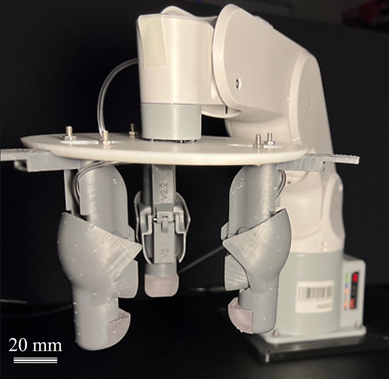
Picture of the final TPU-MBSPA-driven 3-point Soft-Rigid Hybrid Gripper assembly attached onto a collaborative robotic manipulator as an end effector. A scale is included to provide the size information of the presented SRH gripper.
Gripper workspace and demonstration
To explore a wide range of objects that the 3-point SRHG can manipulate, the gripper workspace was first derived using the geometric configuration of the SRHG. Using objects of different shapes and sizes, this gripper workspace was verified experimentally via open loop gripping with pressure input. The comparison result of the experimentally determined contact space for stable gripping and the expected contact trajectory for stable gripping are as shown in Figure 9A. The SRHG was capable of stably gripping objects of any sizes and irregular shapes, as long as the outer contour of the object were within the experimentally derived gripper contact space and have made contact with minimal of two fingers. Notable unique case was when the gripper was able to make stable grip via lateral pinching of only two fingers, which was made possible due to the rigid hinge providing lateral counteractive force against the object. In cases of gripping irregularly shaped objects, certain fingers contacted the object earlier than the others; when this had occurred, the finger that made contact earlier complied to the shape of the object and did not apply additional forces until the other fingers made full contacts with the object.

The stiffness of the SRHG gripper determines the ability of the gripper to provide stable gripping and lifting of the objects. To investigate the compliance of the SRHG, a tapered cylinder was used. Starting from the three fingers of the SRHG contacting the smaller diameter of the tapered cylinder, forces were applied to the fingers when the tapered cylinder was moved to the larger diameter section. As shown in Figure 9B, the result showed that the range of variable stiffness of SRHG was 26.5 N/m to 76.2 N/m. This implies that the capability of the SRHG to vary its stiffness depends on the delicacy of the object. This is comparable with other soft grippers providing variable stiffness.51,52 As summarized in Figure 9C, the SRH gripper was able to securely grip a wide variety of objects as small as 7 mm in diameter, as light as 2.2 g, as large as 68 mm in diameter, and up to 1 kg calibration weight. The objects and their respective mass, size, as well as the pressure and joint stiffness required to perform holding grip stably are summarized in Table 2. While gripper stiffness investigation focused on the lower operating pressure range, the maximum payload stable holding grip was 1 kg calibration weight, which was enabled by applying a 77 kPa internal pneumatic pressure. Even though detailed evaluation has not yet been done with higher operating pressure ranges, this provided an insight that the proposed SRHG has great potential to be extended for use in general robotics requiring higher stiffness and payloads.
List of Objects Gripped with Soft-Rigid Hybrid Gripper and Their Respective Gripping Diameter and Mass
Concluding remarks and future directions
In conclusion, this study systematically explored a novel SRH system, utilizing multilayered bellow-shaped SPA (MBSPAs) for object manipulation. The research provides a deep insight into the fabrication process and characterization of TPU used in MBSPAs, establishing its superior durability and strain tolerance. The implementation of a hyperelastic model in conjunction with FEM simulations has facilitated a comprehensive understanding of material behavior under diverse operational conditions. Our FEM simulations findings revealed a maximum strain of 87 % at an input pressure of 40 kPa, closely mirroring the results obtained from experimental trials through the material models formulated using only uniaxial tensile testing. This congruence between simulated and empirical data paves the way for the future development of complex soft-rigid robotic structures through fully digital design methodologies. By leveraging the simulation techniques, we have significantly reduced the reliance on a trial-and-error approach in the design process, thereby enhancing efficiency and precision in the development of robotic systems.
This study introduces two types of SRH systems, the revolute joint (SRH-RJ) and the prismatic joint (SRH-PJ), both using TPU-MBSPAs. This is the first time where a multilayered bellow-type soft pneumatic actuator collapsible to minimal thickness is used in the context of SRH configuration with fixed axis of motion. Through rigorous experimental testing, the robustness and repeatability of these joints under various conditions were confirmed. The performance of the SRH-RJ and SRH-PJ in terms of displacement, frequency response, durability, force output, stiffness, and power density has been thoroughly studied and validated. The SRH-RJ notably achieved a maximum angle displacement of 90 degrees with an input pressure as low as 13 kPa, while delivering a substantial maximum tip force output of nearly 5 N at zero degrees of obstruction. This performance significantly surpasses that of previous systems of similar size. In addition, the SRH-RJ demonstrated stable and consistent operation throughout its full range of motion at a frequency of 1.2 Hz. Moreover, after 15,000 cycles, the SRH-RJ exhibited only an additional 0.34% expansion in its original angular displacement range, a figure that is negligible. This minimal change not only attests to the SRH-RJ’s impressive repeatability but also confirms its long-term durability, underscoring its potential for sustained use in demanding applications.
We have also introduced a design featuring a protective-shell structure that encapsulates and safeguards ultralow profile SPA across their entire range of motion. This novel protective shell also serves a dual purpose by effectively preventing radial bulging in bellow-style actuators. Notably, the force required to inhibit this bulging was determined to be 2.2 N, demonstrating the efficacy of the design in maintaining the structural integrity and functionality of the actuators under operational conditions.
Finally, the practical applicability of these joints is exemplified through the creation of a versatile three-point SRHG. This SRHG excels at securely handling a broad spectrum of objects, ranging from those as small as 7 mm in diameter and as light as 2.2 g, to items as sizable as 68 mm in diameter. It also proves capable of managing objects weighing up to 1 kg, demonstrating its suitability for a wide array of tasks and its adaptability in diverse operational contexts. Despite certain limitations observed, such as discrepancies between the experimental and simulation results, this study lays an essential groundwork for future research and optimization in the field of soft robotics. The promising outcomes of this research suggest that with further improvements, the SRH system with MBSPAs could potentially revolutionize delicate object manipulation in numerous industries, particularly in food and agriculture.
Future work may include further optimizing the system and fine-tuning the gripper for specific berry harvesting such as blueberry, raspberry, and strawberry, which present different requirements. To address manipulation tasks involving delicate objects, the stiffness variability of the presented gripper can be used to the full extent. Specifically, the joint stiffness of the gripper can simply be tuned by changing the internal pressure, allowing control over the maximum normal force exerted to prevent damage to delicate objects. Although the SRH modules were tested under simulated version of the common outdoor environments, field testing may also commence to validate the efficacy of the protective shell in safeguarding the internal soft components. For instance, berry fields often present environmental factors that may damage soft actuators, making it crucial to design a protective shell for our system that can function effectively under the accumulation of mud and dust, as well as UV radiation of the sun. Long-term experiments under such exposures can help validate the capability of the protective shell to maintain the system’s functionality in harsh environments, ensuring consistent performance and reliability in real-world agricultural settings.
Alternative to gripper-type end-effectors, a SRH grasper can also be formulated using the presented work toward delicate object manipulation and handling. 53 Specifically, the SRH grasper comprises of individual SRH module presented in this work, hence the technology shared in this work in a larger scale. It should also be noted that while scaling down of the proposed SRH modules is not explored in this study, potential hindrances are anticipated. These may include the required high precision and accuracy for alignment, reduced displacement, and smaller force output magnitudes. Overcoming these prospected issues can enhance the applicability of the proposed SRH system in smaller-scale applications. Nevertheless, such systems hold potential applications in prostheses, teleoperation, and ensuring safe physical human–robot interaction. Moreover, the integration of sensor technologies can enhance these systems by providing real-time feedback, enabling more precise control over manipulation tasks prospected in this paper. This includes leveraging recent and near-future technological advancements in soft sensorization technologies, whereby the TPU layers are equipped with sensors to acquire real-time information such as internal pressure, contact forces, and angular displacement.54–56
Footnotes
Acknowledgments
The authors would like to thank Douglas Hirst (Laboratory Technologist, MME Department, University of Waterloo) for his technical support and assistance with material testing. The authors would also like to thank Calvin Young (Lab Instructor, SYDE department, University of Waterloo) for equipment rental management of the UniVert system.
Authors’ Contributions
P.S.L.: Conceptualization, methodology, software, investigation, writing—original draft, and visualization. C.S.: Validation and investigation. R.Z.G.: Conceptualization, writing—review and editing, and visualization. J.D.: Software, validation, and investigation. M.R.-N.: Validation and investigation. C.L.R.: Resources, writing—review and editing, supervision, and funding acquisition.
Author Disclosure Statement
The authors declare no conflict of interest.
Funding Information
The authors acknowledge the support from Natural Sciences and Engineering Research Council of Canada (NSERC) through grants to C.L.R. [RGPIN-04151-2018] and through scholarships to P.S.L., R.Z.G., J.D., and M.R.-N. The authors would also like to acknowledge Abbotsford Community Foundation Agricultural Enhancement Grant for their funding support.

References
Supplementary Material
Please find the following supplemental material available below.
For Open Access articles published under a Creative Commons License, all supplemental material carries the same license as the article it is associated with.
For non-Open Access articles published, all supplemental material carries a non-exclusive license, and permission requests for re-use of supplemental material or any part of supplemental material shall be sent directly to the copyright owner as specified in the copyright notice associated with the article.
