




Abstract
The art of origami has gained traction in various fields such as architecture, the aerospace industry, and soft robotics, owing to the exceptional versatility of flat sheets to exhibit complex shape transformations. Despite the promise that origami robots hold, their use in high-capacity environments has been limited due to the lack of rigidity. This article introduces novel, origami-inspired, self-locking pneumatic modular actuators (SPMAs), enabling them to operate in such environments. Our innovative approach is based on origami patterns that allow for various types of shape morphing, including linear and rotational motion. We have significantly enhanced the stiffness of the actuators by embedding magnets in composite sheets, thus facilitating their application in real-world scenarios. In addition, the embedded self-adjustable valves facilitate the control of sequential origami actuations, making it possible to simplify the pneumatic system for actuating multimodules. With just one actuation source and one solenoid valve, the valves enable efficient control of our SPMAs. The SPMAs can control robotic arms operating in confined spaces, and the entire system can be modularized to accomplish various tasks. Our results demonstrate the potential of origami-inspired designs to achieve more efficient and reliable robotic systems, thus opening up new avenues for the development of robotic systems for various applications.
Introduction
Soft morphing robots are capable of flexibly altering their shapes in response to changes in the environment, which greatly enhances their functionality. 1 Soft shape morphing is characterized by a number of important features, including deployability, adaptability, and lightness, which enable the robots to undergo versatile and complex motion changes. Such robots have found a wide range of applications as inflatable actuators,2–4 stimulus-responsive actuators,5–7 tensegrity robots, 8 and origami and kirigami actuators.9,10 Despite their many advantages, the lack of structural stiffness in these soft morphing robots has limited their widespread use in various robotic applications.11–15 To overcome this limitation, it is necessary to improve the stiffness of the robots while preserving their soft morphing characteristics.
Origami has the unique ability to transform flat substrates into complex three-dimensional (3D) configurations that are deployable and reconfigurable, thanks to the efficient guidance of shape changes. 16 However, the inherent softness of the materials and the presence of numerous folding lines result in low stiffness, which limits the use of origami structures in practical applications. Recent research efforts have focused on developing composite origami substrates that combine rigid facets with soft membranes, which have led to improvements in the lateral stiffness of origami structures.17,18 However, the axial stiffness of these structures remains low in the absence of lockers, and the soft creases in the joints lack stiffness. Other approaches have involved adding stiffness components to origami structures,19,20 but this approach can hinder large shape changes and negate the unique advantages of origami.
Another promising approach involves the use of geometric bistability in original origami structures, which can maintain their shape without additional structures.21,22 This approach preserves essential characteristics such as deployability, and the shape remains stable under static conditions. However, the structural stiffness of such origami structures is insufficient due to their complex nature, which makes self-folding difficult. To address these issues, there is a need for an origami pattern with a sheet configuration that maximizes bistability and an effective actuating system.
Origami robots have been actuated using various methods, including shape memory alloys (SMAs),10,23 shape memory polymers (SMPs), 24 magnetic fields, 25 and tendon-driven13,26 and pneumatic methods. 21 SMAs and SMPs can generate versatile crease motions, but their use increases the complexity of the system. SMPs are unsuitable for origami structures that are stiff and large scale as they do not generate large forces. SMAs require long cooling times, making them inappropriate for immediate actuation needs. Magnetic fields have the advantage of not being tethered, but their working environment is confined to within the coil that generates the magnetic field. Tendon-driven methods are easy to trigger intuitively, but determining the most appropriate wire paths and directions can be challenging. In addition, tendons cannot be used if the robot must execute large and complex tasks.
Pneumatic pumps/valves offer a simple actuation method, and a uniform force can be applied to the entire structure despite their bulky size. Centimeter-scale, bistable origami soft morphing robots can be actuated using this method to achieve many complex shape changes.
Despite these advantages, pneumatic origami robots are limited in their types of movements due to being preprogrammed. This can result in reduced utility despite their large volume. The limitation of preprogrammed movements in soft robots can be addressed by modularizing the actuators. This enables easy reconstruction, replacement, and modification of actuator components according to the specific task. 27 In this process, it is crucial to simplify the control system as the number of valves and pneumatic wires increase proportionally with the number of actuators.28,29 Therefore, it is necessary to implement a simplified pneumatic system 30 for bistable actuators to reduce the overall control system and volume.
To address the limitations of current systems, this research describes self-locking pneumatic modular actuators (SPMAs) for robotic applications. These actuators exhibit various shape changes and high-level structural stiffness. The design involves new origami-based patterns capable of linear and rotary morphing, as well as embedded magnets in the sheets to allow locking. Modular structures with simplified pneumatic systems that use self-adjustable valves were created. The demonstration of a robotic arm using SPMAs was also provided, representing the first steps toward a modular origami robotic system enabling human–robot interactions in confined environments.
Methods and Materials
Origami-inspired self-locking structures with shape-morphing capabilities
The origami-inspired structures are composite sheets fabricated via layering. To create these composite sheets, the top and bottom layers are bonded and sealed using an adhesive layer made of thermoplastic polyurethane film via heat-pressing. Shape-morphing is induced by inserting pattern facets between the membranes used to create the composite sheets. 17 To enhance structural stiffness, magnets were embedded in the sheets (Fig. 1A). The fabrication process is described in detail in the Materials and Methods and Supplementary Figure S9 in Supplementary Data. The prototype linear morphing actuator, which can transform from a flat initial structure to a deployable 3D cube, incorporates these magnets to ensure bistability when the deployed sheet is flat (inset of Fig. 1A).
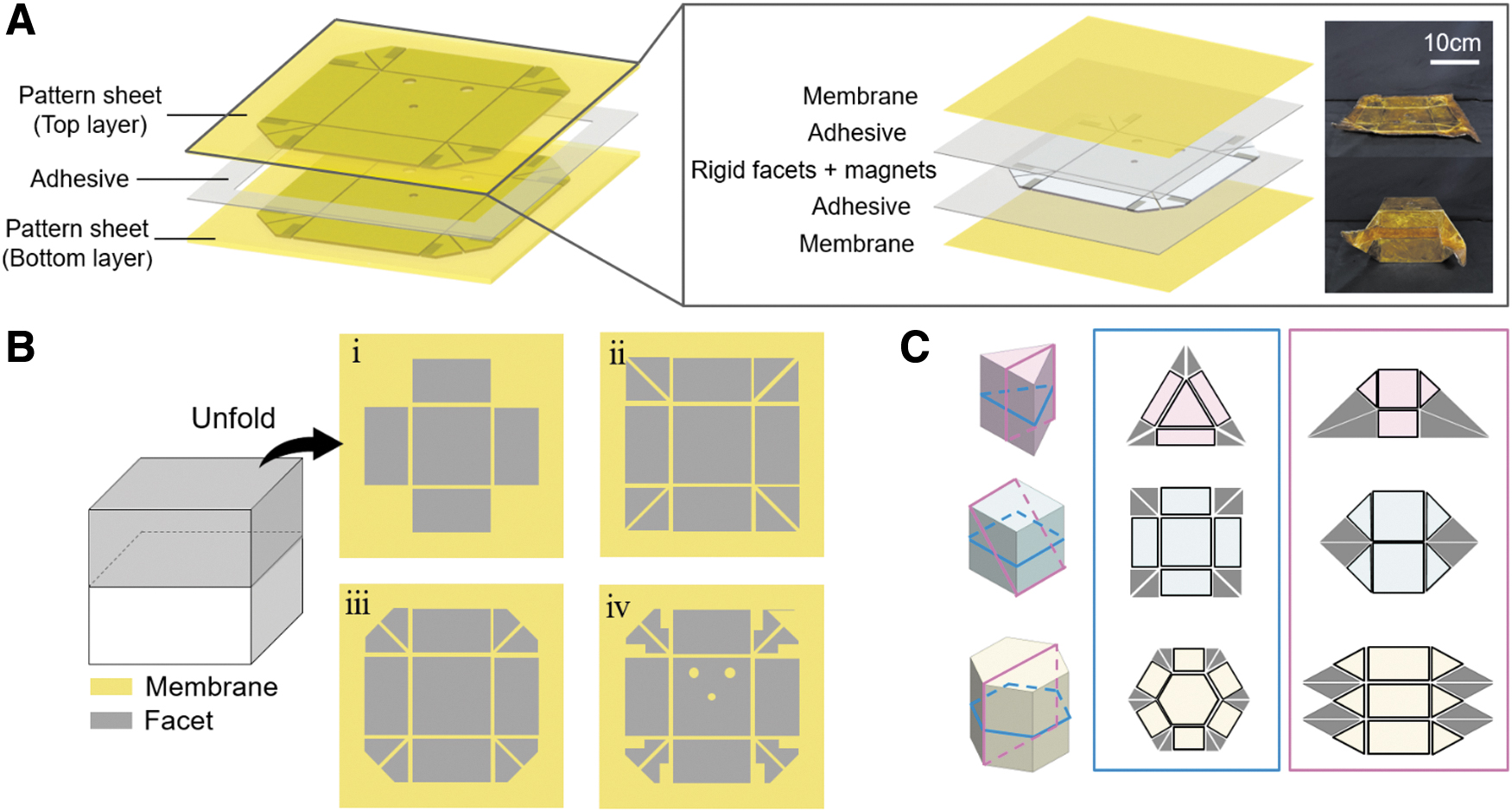
Design patterns of SPMAs based on planar figure.
The origami pattern design was inspired by a planar figure. The SPMA for linear morphing was designed in four steps (Fig. 1B). First, the 3D figure was cut in half (in the vertical plane of the morphing direction) and developed on the membrane. Offsets for edge adhesion enabled sealing of a pneumatic pouch. Second, rigid vertex patterns were added to remove redundant degrees of freedom by imposing geometric constraints and locking the origami structure. However, during state transformation of the origami actuators, the rotation of these vertex patterns resulted in the development of gaps between the upper and lower layers. These gaps reduced airtightness, particularly at the vertices. This issue was addressed by removing some of the rigid facets of the vertex pattern and expanding the flexible membrane. Finally, the pattern was completed by replacing the rigid facets with magnets and pneumatic hose fittings.
Figure 1C demonstrates the possibility of designing patterns that enable shape transformation of polyhedral shapes. By constructing the unfolded diagram of each 3D shape in different ways, a variety of shape transformations can be achieved, including both linear and rotational transformations when the partition plane is perpendicular to the direction of movement. To aid in comprehending the shape of pattern sheets, the unfolded diagrams are depicted in color, while the added vertex patterns are presented in gray.
In this study, a rectangular pattern was chosen as it is easy to assemble and fabricate, as shown in Figure 2A. Several parameters were considered in the design, including the length of the base facet (l), side length (r), angle of the vertex pattern (θ), gap between two facets (d), and the side length of an expanded flexible membrane area (x). The length of the base facet is linked to the area of the base facet, while the side length is linked to the height of the module. Unlike in a linear module, the side facet in a rotary module is dependent on the base facet, and it is not possible to adjust the lengths of the side facets separately.

Geometrical analysis for optimization of design parameters.
In the fabricated prototypes, l and r were arbitrarily set to 100 and 50 mm, respectively. d was set to 2 mm (twice the thickness of the facet) to allow complete folding. The variables l, r, and d are determined by the size of the prototype and the origami folding, and are thus considered constants. In contrast, the design parameters θ and x are utilized for adjusting the morphing shapes and optimizing the vertex patterns, respectively. θ varied with module maximum height and shape transformation. Depending on θ, the linear module adjusts the height via shape deformation of a decahedron, and the rotary module adjusts the rotation angle via shape deformation of a rhombohedron.
A detailed analysis about the height of linear and rotary patterns according to θ is shown in Supplementary Figure S1. Figure 2B shows a graph representing the equation obtained for maximum height through the analysis. To maximize the height, and therefore to maximize the length and angular change, we set the angles (θ) of the vertex patterns of the linear and rotary modules to 45°.
The vertex patterns play a crucial role in locking and guiding the shape morphing of the modular actuator. However, triangular vertex facets pose a challenge in enclosing the pneumatic actuators. As a result, it is necessary to modify the vertex patterns by reducing the rigid facets. Figure 2C shows the relationships between A (the area of the vertex pattern during transformation of the modular actuator) and x (the length of one side of the expanded membrane). ϕ denotes the rotation angle of the side facets in the linear module and the movement angle between the base facets in the rotary module. When ϕ is 0°, the module is deployed; when ϕ is 90°, the module is flat. To simplify the optimization of the vertex pattern shape, we assumed that sealed actuators could be fabricated during all conversion processes by reducing the areas of the rigid facets by the maximum gap areas in the vertex patterns, and expanding the flexible membranes into the removed areas. Therefore, the relationship between x and A becomes:
A detailed analysis of gap area A is shown in Supplementary Figure S2. All parameters
Actuation mechanisms of the inner and outer chambers
Most origami-based pneumatic actuators use shape-morphing techniques to achieve expansion by applying positive pressure within a chamber, and contraction through the application of negative pressure or the removal of air.31,32 This method allows for uniform force transmission throughout the body, facilitating shape-morphing. However, the mechanical locking of SPMAs poses a challenge. Applying positive pressure causes the actuator to inflate, making it difficult to lock as the vertex pattern detaches. Applying negative pressure leads to the actuator being crushed and locked, rendering state conversion impossible. To address this, we developed a reversible state transformation technique by actuating the inner and outer origami chambers. To convert from a flat to a deployed state, a force is applied in the morphing direction, folding the origami.
Therefore, the inner chamber of the bellows was fixed to the base facets of the top and bottom layers to allow both linear (Fig. 3A) and rotational (Fig. 3C) expansions. During deployment, positive pressure expands the inner chamber to perform state transformation. To convert from a deployed to a flat state, the vertex patterns must be detached (unlocked) by applying pressure to the flat fittings, and air must then be exhausted. The linear and rotary state conversions of SPMAs are illustrated in Figure 3B and D. The specific state conversion process is demonstrated in Supplementary Movie S2.

Actuation system for self-folding.
Achieving reversible conversion of SPMAs involves the use of a bellows chamber and magnets. However, optimizing these components using analytical methods is challenging due to the complex composition of their materials, which makes their mechanical properties difficult to determine. Therefore, we conducted experiments to determine appropriate locking and unlocking conditions. Specifically, we tested three bellows (Fig. 4A) fabricated via layering 33 of different proportions of fabrics and films, which resulted in varying mechanical properties. To ensure maximum airtightness, we used strong thermoplastic polyurethane polyester fabric for all external membranes. The internal membranes were composed of polyimide (PI) film or fabric only, or combinations of the film and fabric; the stiffness thus varied, which affected the restoration force. We tested four magnets of different sizes (150, 200, 250, and 300 mm2; M1–M4, respectively); all magnets were 1.5 mm thick.

Required conditions to select bellows chambers and magnets.
We required the bellows inner chamber to lift its own weight of modules (at least three modules), and additional objects, to the height required for locking. Therefore, the payload of bellows should be >1.3 kg considering the weight of each module, and the extension length of bellows should be longer than the stroke of the origami module. The stroke of the origami module is defined as the difference between the height of a module (100 mm) and the thickness of a module (10 mm).
Another essential requirement was that, under maximum volumes, the magnets should be entirely separated to avoid relocking. Thus, the restoring force imparted by the bellows and gravity acting on the modules should be larger than the magnetic force between the vertex patterns. This can be simplified as follows:
where
Finally, after all magnets are detached, the module should be completely flat. To achieve this, the sum of the magnetic forces attracting the top and bottom layers and the restoring force of the bellows should exceed half the gravitational force acting on the origami chamber. This third requirement can be expressed more concisely as follows:
where
We conducted experiments to investigate the performance of the bellows chamber under varying payloads, magnetic forces, and restoring forces, and performed static analyses to determine whether the locking and unlocking conditions were met. As shown in Figure 4B, we found that bellows B3, which was composed of 50% fabric and 50% PI film, did not meet the first conditions for locking because it failed to lift the load at the maximum pressure of 55 kPa, and was therefore discarded.
Equation (2) represents the second condition for unlocking. To simplify the static model when the volume was maximal, we projected the vertex patterns of the linear and rotary actuators onto the xy-plane (Fig. 4C). Each joint was modeled as a revolving hinge with the pin of a slider operating in the morphing direction, and the bellows was modeled as a tensile spring. To imitate each morphing direction, the linear module was mapped to a linear slider and the rotary module to a curved slider. A detailed description of the equations is included in Supplementary Figure S4.
Equation (3) represents the third condition for flattening. It states that the entire magnetic force of the linear module is
In Figure 4D, the black rectangles are magnet–bellows pairs that satisfy the third condition. Therefore, B2–M3 and B2–B4 were selected for linear and rotary modules, respectively, to maximize stiffness among the all satisfied conditions.
Sequential actuation of multimodules using simplified pneumatic circuits
Each pneumatic actuator requires several components, including a valve, a hose line, and a pump. If each actuator is controlled separately, the entire system can become bulky and heavy. It is also complicated and inefficient to control a bistable actuator individually because it requires mapping input and output signals. For example, assuming that the deployed state is 1 and the flat state is 0, there is no significant difference between the [1, 0, 0] and [0, 1, 0] states of the three multimodules in terms of length adjustment. This is because no matter what module is deployed, the length of extension is the same. Therefore, the pneumatic system can be simplified by generating sequence of actuation automatically.
To accomplish this, the valves are embedded in SPMAs, and valve switching should be designed to reflect the geometrical characteristics of the SPMAs. The requirements for multimodule actuation are shown in Figure 5A. The vent port of the outer SPMA chamber of the layer undergoing shape morphing should be open to allow multimodule deployment, because air then flows freely in and out as the volume of the origami outer chamber changes. During flattening, when the outer chamber is fully inflated and unlocked, only the vent port of the layer under conversion should be open. After the module is completely flattened, the pressure ports of both the flattened and shape-shifting modules should be opened to apply pneumatic pressure to the next layer. In addition, all valves in flattened modules should be connected; they then serve as a single pneumatic hose that stably transmits pneumatic pressure.

Actuation system of multimodules.
A novel solution to satisfy the aforementioned conditions is proposed in this study, which involves self-adjusting valves (Fig. 5B). As the hose line changes with SPMA shape changes, it is too difficult to control the valves using conventional methods, such as electricity or pneumatic pressure. Therefore, the proposed valves switch their states passively based on the shape changes of the outer chamber. The valves have four ports and two positions (4/2 valves); their structures are simplified by combining the pressure and vent ports. The vent ports of all multimodules are controlled by a single solenoid valve. During deployment, when a positive pressure is applied to the bellows inner chamber, all ports of the outer chamber open.
Conversely, during flattening, the valve linked to the second module is closed to unlock the first module reliably. When the first module is completely unlocked, the vent port with the solenoid valve is opened to exhaust that module. Subsequently, when the first module is completely flat, the valve connected to the second module is opened, and the ports of the pressure line are then integrated into one hose via the ring magnets.
The newly developed self-adjustable valves are equipped with a crank-slider structure, as illustrated in Figure 5C. The valve design parameters include the distance between holes (k) and the lengths of the linkages L1 and L2. When the module is in the deployed state, the valve is completely closed and the distance between the holes is at its maximum. Conversely, the valve is fully open when the module is flat and the distance between the holes is 0 mm. A commercial pneumatic hose (diameter d = 10 mm) was used; the large diameter increased the flattening speed. The primary goal of valve design is to optimize the value of k. Thus, the lengths of the linkages L1 and L2 were determined as follows.
It is crucial that the valve holes remain misaligned until the chamber's volume is maximized. Subsequently, each valve should be closed until all the magnets are detached, resulting in unlocking of the module. This process can be expressed as follows:
where
For the linear module, L1 and L2 were 28 and 50 mm, respectively; for the rotary module, L1 and L2 were 17 and 32 mm, respectively. All valves were then designed and assembled (Fig. 5E) with thicknesses approximating those of the bellows actuator to avoid reducing shape-change performance. The hose lines were linked through connectors and ring magnets, which enable the direction of the hose to switch from the current shape in the outer chamber (n) to a different shape (n + 1). Silicone rings were installed under the sliders to prevent air leakage and reduce friction, and spacers were installed to guide the shape of the outer chamber, thereby stabilizing the hose connection.
Figure 6A presents the overall structure of the multimodules, and various structures are possible by adjusting the lengths of the linear actuators and angles of the rotary actuators. While the same type of actuators can be directly connected, a different type of actuators requires compatibility blocks to connect them as their valve holes are not aligned. These compatible blocks enable connection between different valve ports. SPMAs can be configured into the desired robotic arm in various combinations. In addition, it is easy to assemble and disassemble to suit the work environment, making it easy to modify. The specific fabrication process of the modules is described in Supplementary Figure S11.

Multimodules consisting of linear and rotary SPMAs.
Figure 6B and C shows the actuation process of multimodules with three linear modules and two linear modules and one rotary module, respectively (Supplementary Movie S3). The operating mechanisms in both cases are the same. During deployment, when pressure is applied to the inner chamber, the module at the top is first deployed, and the other modules are then sequentially locked and deployed. During flattening, the modules are sequentially unlocked and flattened, beginning with the module at the bottom. The embedded valves are self-adjustable during both deployment and flattening. The deployment time is shorter than the flattening time due to the difference in chamber sizes and actuation complexity.
Results
Performance verification of the SPMAs
The SPMA self-locking capability and stiffness are the key achievements of this article. We experimentally explored the maximum possible loads and stiffnesses of the linear and rotary actuators. We examined deployed outer origami chambers; the setups are shown in Supplementary Figures S5–S8. The linear modules had a length of 120 mm, width of 120 mm, and height of 100 mm; the rotary modules had a length of 120 mm, width of 120 mm, and height of 120 mm. Our experiments utilized magnets with dimensions of 250 and 300 mm2. Simple load experiments can be found in Supplementary Movie S1.
Figure 7A shows the compressive load capacities and stiffnesses of the SPMA. The linear modules exhibit a significantly larger load capacity than the rotary modules, despite having twice as many magnets. This is because the applied force lies on the unlocking axis of the linear modules. Therefore, when a large load is applied to the linear module, the magnets are detached and the lock is released. This is because the direction of motion and the direction of the load are aligned. On the contrary, the direction of the applied force differs by 45° from the axis of the vertex pattern in rotary modules, which do not unlock even when a large force is applied. As a result, rotary modules can withstand much larger forces, with a maximum load of 784 N. Furthermore, since SPMA sheets are constructed using a soft membrane, an adhesive, and flexible facets, they do not fracture even when a substantial force is applied.

Experimental results of the structural stiffness (Sample size: n = 3, shear experiments of rotary modules: n = 2).
In Figure 7B, we present the bending load capacities and bending stiffnesses of the linear and rotary modules. As expected, the bending load capacities are lower than the compressive maximum loads for both types of modules because the former is dependent on the bonding strength of the adhesive between the layers, while the latter relies on the origami structure and magnets. The main reason for this is that the adhesive layer positions are different. In the case of linear module, the two layers are bonded in the center, while in the case of the rotary module, they are bonded at both ends. Therefore, the moment arm of the rotary module is larger than the linear module. Consequently, when the same force is applied, the adhesive part of the rotary module is easy to peel off.
Furthermore, we observed that the initial stiffness of linear modules is higher than that of rotary modules. This is because the side facets of the linear module have a higher bearing capacity under compressive loads than the side facets of the rotary module. Side facets of the linear modules are arranged in a rectangular shape in a row, while those of the rotary module are arranged to be slightly inclined in a triangular shape.
Figure 7C shows the shear load capacities and shear stiffnesses. The bonding strengths of the adhesive layers significantly influence the maximum shear load. The linear modules support a larger shear load than the rotary modules, because the adhesive plane of the linear modules lies parallel to the direction of the applied force. In contrast, the maximum load in the shear direction for the rotary modules is anisotropic. Assuming clockwise deployment, the modules have greater difficulty withstanding shear when the force is applied counterclockwise, because the direction of unlocking is the same as the counterclockwise direction.
We confirmed that not only compressive stiffness, but also shear and bending stiffnesses were high. Therefore, the deployed shapes were stable despite external disturbance.
A shape morphing robotic arm with a mobile base
The modular nature of the SPMA allows for the implementation of various morphing abilities through a combination of respective actuators with different directions and sizes. With its thin initial length of only 2 mm, it has high deployment potential and can be utilized in robotic applications in places where space is limited. To demonstrate this potential, we combined the SPMA robotic arm with a mobile base in a narrow warehouse-like environment (Fig. 8A). The robotic arm consists of a gripper (RH-P12-RN, ROBOTIS), a counterweight box, and elastic bands. The counterweight box contains weights to offset the torque caused by the weight of the gripper, while the elastic bands assist in deploying the modules by applying an opposing force to the biased weight. This design enables the lifting of the gripper (500 g) and additional objects.

Application as a foldable robotic arm.
We demonstrated the task of moving objects on a shelf using modified SPMAs combined with a mobile base (Fig. 8B and Supplementary Movie S4). The SPMA robotic arm extends to the height of the shelf through the locking and deployment process, and grasps the object on the shelf using the gripper. The robotic arm is then converted into a flat state through the unlocking process. We also demonstrated that the robot can pass under shelves, showcasing its utility in a limited space. Furthermore, each module can be customized and rebuilt based on the height of the shelf, allowing for an adaptive design depending on the environment.
Conclusion and Discussion
In this article, we used the principles of origami to construct SPMAs using shape-morphing sheets. These cubic modular actuators can be manufactured in various polygonal 3D shapes by changing the parameters of the patterns. The linear actuator has a high length change ratio, and the rotary actuator moves at a constant angle allowing for precise positioning (Supplementary Fig. S10 and Supplementary Table S1). By combining linear and rotary modules, a programmable 3D architecture can be created, such as modular robot arms that perform simple repetitive tasks.
The design and fabrication of sheets with embedded magnets and facets are detailed in this article. These self-locking actuators have shown a significant increase in stiffness, which was experimentally verified. The weight of the linear and rotary actuators was only 201 and 213 g, respectively, without the valves and bellows, and they could handle loads of 264 and 784 N, respectively. The entire actuator system is modularized for practical applications, and self-adjustable valves were used to simplify the pneumatic system. These valves are passively controlled by the state change of each module, eliminating the need for external power. Each module can be easily assembled and replaced using compatible blocks.
However, SPMAs have several limitations that need to be overcome. The first limitation is the bound on the number of modules that can be connected, which is about four due to the inner chamber of the bellows being able to lift only 1.3–1.5 kg. In addition, twisting or bending more than two modules is difficult due to the weight of the modules, and the torque required is proportional to the number of modules. To address these limitations, a gravity compensation mechanism will be added, and module weight will be reduced. We expect that our continuing efforts, and the use of additional sensors, will yield robotic actuators that work reliably and safely in confined environments, such as warehouses.
Footnotes
Author Disclosure Statement
No competing financial interests exist.
Funding Information
This work was supported by the National Research Foundation of Korea (NRF) Grant funded by the Korean Government (MSIT) (Nos. NRF-2019R1A2C2084677, RS-2023-00208052) and the Korea Evaluation Institute of Industrial Technology (KEIT) grant funded by the Korean Government (No. 20008912)

References
Supplementary Material
Please find the following supplemental material available below.
For Open Access articles published under a Creative Commons License, all supplemental material carries the same license as the article it is associated with.
For non-Open Access articles published, all supplemental material carries a non-exclusive license, and permission requests for re-use of supplemental material or any part of supplemental material shall be sent directly to the copyright owner as specified in the copyright notice associated with the article.
