




Abstract
This article presents a novel extensible continuum robot (ECR) with growing motion capability for improved flexible access in transoral laryngeal procedures. The robot uses an extensible continuum joint with a staggered V-shaped notched structure as the backbone, driven by the pushing and pulling of superelastic Nitinol rods. The notched structure is optimized to achieve a wide range of extension/contraction and bending motion for the continuum joint. The successive and uniform deflection of the notches provides the continuum joint with excellent constant curvature bending characteristics. The bidirectional rod-driven approach expands the robot's extension capabilities with both pushing and pulling operations, and the superelasticity of the driving rods preserves the robot's bending performance. The ECR significantly increases motion dexterity and reachability through its variable length, which facilitates collision-free access to deep lesions by following the anatomy. To further exploit the advantages of the ECR in path-following for flexible access, a growing motion approach inspired by the plant growth process has been proposed to minimize the path deviation error. Characterization experiments are conducted to verify the performances of the proposed ECR. The extension ratio achieves up to 225.92%, and the average distal positioning error and hysteresis error values are 2.87% and 0.51% within the ±120° bending range. Compared with the typical continuum robot with a fixed length, the path-following deviation of this robot is reduced by more than 58.30%, effectively reducing the risk of collision during access. Phantom experiments validate the feasibility of the proposed concept in flexible access procedures.
Introduction
Transoral robotic surgery (TORS) has become a newly emerging solution for treating oropharyngeal and laryngeal diseases with the merits of making the operation more precise, lowering surgeon fatigue during lengthy surgical procedures, and reducing patient pains.1–3 Currently, only a few commercial robotic systems have received FDA approval for TORS. The Da Vinci SP® system (Intuitive Surgical, Inc., CA) adopts articulated snake-like joints at the distal end of the instrument for dexterous operation while having difficulty accessing the deep laryngopharynx. 4 The FLEX® robotic system (Medrobotics, MA) utilizes discrete-style joints as the overtube to reach the lesion but lacks compliance for avoiding collision with the larynx. 5
Compared with the redundant manipulator articulated by rigid joints, continuum robots (CRs) generate deflection and shape change through the material's elastic deformation. Their inherent compliance substantially reduces the risk of injury to human tissues, making them more suitable for anatomy access.6–8 Besides, patients are commonly supine during the practical transoral laryngeal surgery, and their tongues tend to unconsciously obstruct the access of surgical tools to the larynx. In traditional laryngoscopy, surgeons usually use a rigid straight or precurved laryngoscope to press the tongue to solve this problem, as shown in Figure 1a. However, the rigid instruments are unable to reach the deep laryngopharynx through the curved lumen. Therefore, existing transoral surgical robots mainly combine a proximal rigid straight section with a distal flexible section to facilitate the smooth access of the robot. The distal flexible section typically adopts the single-section configuration of a fixed length and generates bending motions to be adapted to the shape of the laryngeal access.9–12 However, CRs with a short length have limited reachability, while CRs with a long length have a larger bending radius at the same access process, resulting in collisions of their bodies with the anatomy easily, as illustrated in Figure 1b. Although multisection CRs can improve the access capability, these designs lead to challenges for modeling and control strategies. In contrast, extensible continuum robots (ECRs) feature significantly increased motion dexterity and reachable workspace through their variable length. They can effectively reduce tissue damage and patients' discomfort during procedures through extension following the anatomy, as shown in Figure 1c.
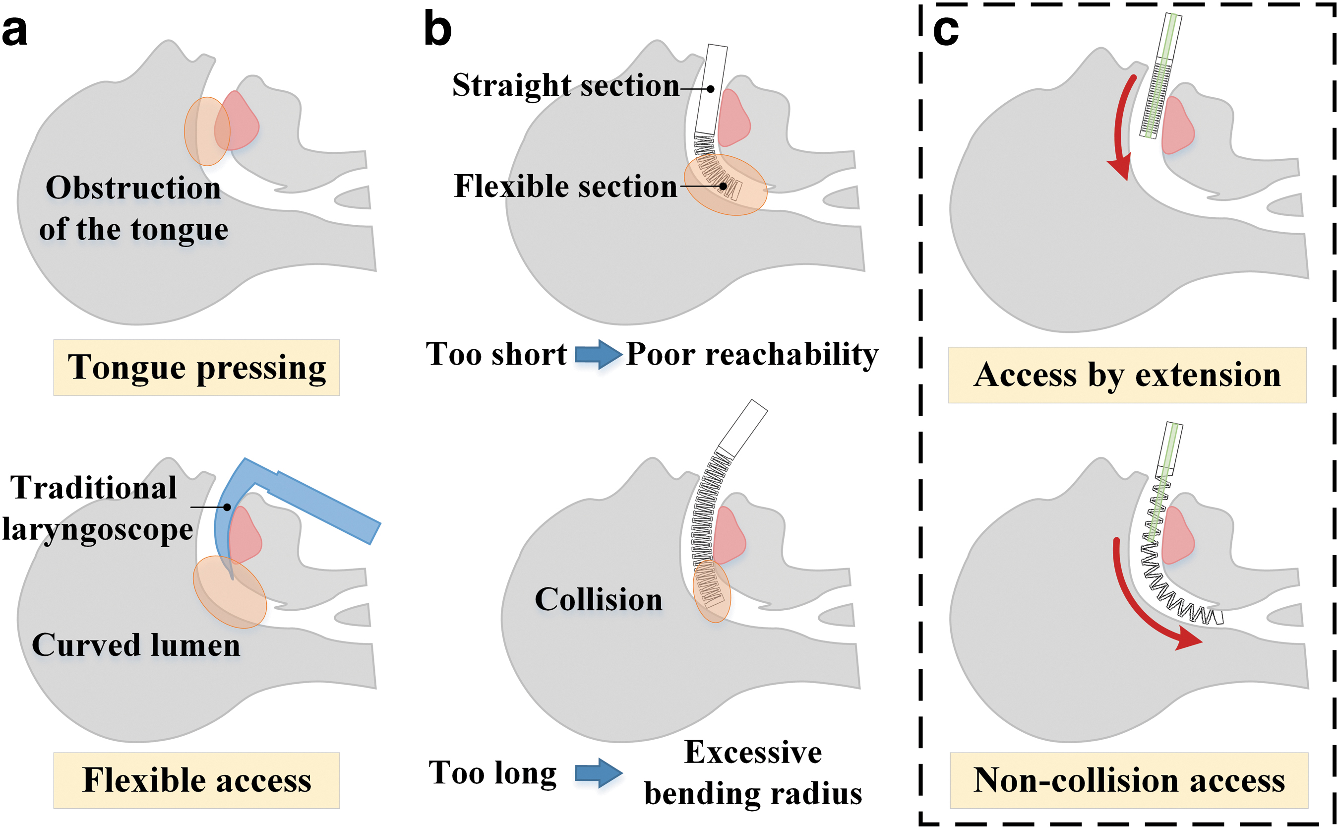
Attempts have been made to focus on designing ECRs13,14 and can be categorized into three types: the pneumatic-driven vine robots, the concentric tube robots (CTRs), and the tendon/rod-driven ECRs. The vine robots utilize pressure-driven eversion to add material to their tips, analogous to the growth of an apical meristem in plants. Some vine robots enable steering motions with additional pneumatic chambers or pneumatic artificial muscles.15,16 The adopted pneumatic-driven steering methods cause an excessive bending radius that makes them challenging for medical applications. Some other medical vine robots are fabricated with predesigned curved shapes through molds and are pressure driven to grow in the predefined shapes. However, their lack of allowance for the change of predetermined paths results in a limited adaptability to different paths.17–19 CTRs are formed by the concentric nesting of precurved elastic tubes.20–23 CTRs possess an excellent extension capability, and their shape and tip pose are controlled by the relative rotation and translation of each tube. However, their movements are limited by the precurved shape of tubes, which usually need to be predesigned for special applications, and the constrained curvature of tubes leading to a lack of dexterity. To develop dexterity and manipulability, Nguyen and Burgner-Kahrs proposed a tendon-driven ECR with concentric tubes as the central backbone and achieved an extension ratio of 5. 24 This design allowed for path-following motions driven by the extension of the concentric tube backbone and tension of tendons with an average positioning error of 3.16% relative to its length. 25 However, the motions of the backbone were prone to cause uneven tension variations in tendons used for bending actuation, making it challenging to model kinematics based on the constant curvature assumption. In addition, several ECRs using tendon/rod-driven approaches are also developed for improving the motion capability. These robots commonly adopt elastic elements as the backbone, and the flexible deflection of the backbone driven by tendons/rods enables their extension/contraction and bending motions. For the tendon-driven approach, Xing et al. designed a 3-degrees of freedom (DOF) ontractible continuum manipulator based on a helical spring backbone and achieved a contraction ratio of 2.26,27 However, this design achieved contraction rather than extension due to the limitation that the driving tendons could only transmit pulling force, which led to the low telescoping ratio and confined workspace. Qi et al. presented a tendon-driven continuum manipulator based on the serially connected double-layer ortho-planar springs backbone with a bending range up to ±160°, but the contraction ratio was limited to 1.43.28,29 The complex design of planar springs led to the large dimension of the robot, limiting its applications in surgical robots. To improve the telescoping capability of the backbone, ECRs based on origami mechanisms have been designed.30–33 They typically relied on the restoring force provided by origami to achieve flexible deflection and possessed a large telescoping ratio. However, the limited restoring force led to the requirement of additional elastic elements for supporting the robot at a large length-to-diameter ratio.34,35 For the rod-driven approach, Wang et al. proposed an ECR based on a soft silicone body. 36 Elastic rods could transmit both push and pull forces, developing the extension capability of the robot. However, its cylindrical backbone was not favorable to producing deflection, limiting the telescoping range to [90, 156 mm] and bending range to [−85°, 112°]. In addition to the abovementioned designs, the notch-based continuum joints allow a wide range of flexible deflection by applying different shaped notches to the elastic tubes.37–44 Such flexible joints are simple in structure, flexible in motion, and easy to integrate with instruments, which have been applied in medical robots. Nevertheless, existing studies on notched continuum joints have focused on improving bending performance and loading capability and have been designed for CRs with fixed lengths.
To explore their application potential in ECRs, this article proposes a rod-driven ECR based on a notched continuum joint backbone. The designed notched extensible continuum joint allows 3-DOF motions and features a large extension ratio and excellent constant curvature bending performance. To reduce collision risks during access, a growing motion approach inspired by the plant growth process has been proposed. This method uses a rigid tube to constrain the growing base of the ECR and a rod-driven method to achieve the extension motions, which mimics the various morphologies of the plant from germination to emergence, thus achieving theoretical zero-deviation path following. The performance experiments and phantom experiments have been performed to investigate the flexible access behaviors of the ECR and its feasibility for applications in transoral laryngeal surgery.
Materials and Methods
Structural design and optimization of the proposed ECR
Overview and mechanical design of the robotic system
The proposed ECR primarily consists of a 3-DOF distal flexible joint, a central rigid insertion tube, and a proximal driving unit, as shown in Figure 2a. The distal flexible joint adopts a rod-driven approach and utilizes a modified bidirectional asymmetric V-shaped notched continuum structure to achieve both bending motion and extension/contraction, as illustrated in Figure 2b. This joint is configured with an outer diameter of 14 mm with a central endoscopic channel (d1 = 5.5 mm) and two instrument channels (d2 = 2.8 mm) for surgical tasks. The proposed notched structure consists of a series of staggered V-shaped notches relative to the central axis of the flexible joint. This design is inspired by the structure of the accordion's bellows, which allows 2-DOF bending deflection and enables a wide range of extension movements through the stretching of the folds. By applying circular nicks at the bottom of the notches to form an approximate flexure, the notched structure is further modified for easier deflection. The modified V-shaped notches convert the deflection of flexure into the opening and closing of the notches, as shown at the bottom of Figure 2b, thus achieving an extensive range of extension and contraction motions of the joint. The large extension ratio allows the distal joint to reach anatomical depths by extension. As the continuum joint is driven to bend, the notched structure generates successive and uniform deflection and produces an approximate bending shape of the joint as a smooth circular curve, which facilitates accurate kinematic-based modeling.

Four Nitinol rods are uniformly distributed circumferentially inside the flexible joint and driven by the proximal driving unit and lead the joint to achieve 2-DOF bending motion and 1-DOF extension/contraction motion. Compared with tendons, the superelastic property of Nitinol rods allows them to produce a wide range of uniform elastic deflection, further improving the constant curvature bending performance of the continuum joint without compromising the miniaturization of the distal joint. The rigid insertion tube (OD = 5 mm, ID = 4 mm) is inserted into the central channel of the joint to constrain the length of the bending segment and further adjust the bending shape of the flexible joint for path-following motion. The insertion tube is made of chrome-plated stainless steel and coated with grease (NyeMed®, Nye) on the outer surface to minimize friction with the continuum joint. To prevent the potential buckling due to the high slenderness ratio of the Nitinol rods, the proximal driving unit is considered and designed, which consists of a linear module for driving the insertion tube and four antibuckling modules based on dual-sheath mechanisms for driving the Nitinol rods, as shown in Figure 2a. The Nitinol rod is covered with a rigid inner sheath, and both are fixed to the slider. Under the actuation of the slider, the Nitinol rod and inner sheath translate inside the outer sheath fixed to the frame. The stroke of the slider is precalculated to ensure that the inner sheath does not detach from the outer sheath. The antibuckling modules keep the Nitinol rods restrained by rigid sheaths throughout, effectively avoiding the possible buckling of Nitinol rods while being pushed over long distances and thus avoiding the loss of pushing force of the rod driving.
Design optimization of the extensible continuum joint
The finite element analysis method is adopted to optimize the notch parameters of the extensible continuum joint to achieve a significant extension ratio. The maximum contraction of the extensible continuum joint is closely limited by the notch angle
For a given extension length,
objective function:
subject to
where L0 is the initial length of the extensible continuum joint and is set to about 90 mm. t denotes the minimum wall thickness of the extensible continuum joint, which needs to be larger than 0.8 mm to avoid fracture considering the limitation of the 3D printing. The parameters of rh, h, and c in Equation (3) have been illustrated in Figure 2b and Table 1. finite element analysis (FEA) was performed in Workbench to obtain the optimal parameters. FEA was performed in the static structure module of ANSYS Workbench software (ANSYS, Inc.). The material of the extensible continuum joint was selected as Nylon PA12 (with Young's modulus of 1700 MPa and Poisson's ratio of 0.4). The optimized parameters were determined by the built-in genetic algorithm in the response surface optimization module, as listed in Table 1.
The Parameters of the Extensible Continuum Robot
Working principle of the growing motion for path-following
The approach for transoral laryngeal surgery can be approximatively regarded as a C-shaped lumen with constant curvature (Fig. 1). The key to performing a successful surgery primarily depends on approaching the lesion more safely and following the narrow lumen to reduce the risk of complications due to interferences between the instruments and human tissues. Thus, it requires the robot to achieve path-following motion with its body profile fitting as closely as possible to the insertion path during access. In other words, the orientation angle (

In contrast, the growth process of the plant is characterized by the extension of its tip along the base section. This dexterous motion allows plants to grow in various environments. The growth process comprises two main phases: the seed germination and the seedling emergence through soil. Seeds will have a portion of the stem buried in the soil during germination, as shown in Figure 3b. This section of the stem below the ground will maintain its shape throughout the plant's growth because the surrounding soil constrains it. The stem above the ground will grow freely with the point where it breaks out of the soil as the growing base point.
Inspired by this process, the proposed ECR performs path-following by means of a growing motion, as shown in Figure 3c. At the initial stage, the extensible continuum joint contracts to its minimum state, and the rigid insertion tube is moved to align with the tip of the joint. In this case, the initial shape of the extensible continuum joint is completely constrained by the insertion tube. The growth motion is performed by pushing and pulling the Nitinol rods with the tip of the insertion tube as the growing base point. This growing motion achieves a full path-following motion without path deviation errors and can be adapted to paths of various curvatures.
Kinematics modeling
Due to the shape constraint by the insertion tube, the distal flexible joint can be segmented into a straight segment and a bending segment, as shown in Figure 4. The nomenclature and frames used for kinematics modeling of ECR are listed in Table 2.

Nomenclature Used in Kinematics Modeling
Forward kinematics
Assuming that the straight segment remains ideally straight, the homogeneous transformation matrix
The constant curvature assumption is adopted to the kinematic modeling by considering the shape of the bending segment as an ideal circular curve. The homogeneous transformation matrix
where

Inverse kinematics for path-following
For a desired circular arc path with constant curvature κd and arc length Ld in 3D space, the unit vector
where
By associating the position vector
Since four driving rods are uniformly distributed along the circumference, the mapping from the configuration space to the actuation space can be obtained as follows:
Experiments and Results
Experimental setup
The experimental configuration for investigating the performances of the ECR is displayed in Figure 5. This experimental setup primarily includes the prototyped extensible continuum joint, six DC motors, six matched amplifiers, a motion controller, an optical tracking unit, and a master joystick. The DC motors (DCX19S; Maxon, Switzerland) with a gearbox ratio of 103:1 (GPX19; Maxon, Switzerland) have been mounted on the driving unit. The control signals are generated by the motion controller (Power PMAC CK3M; OMRON, Japan) and subsequently amplified by the servomotor amplifiers (IMC, PNEP, Germany) to drive the six DC servomotors. The optical tracking unit (Northern Digital, Inc., CA) measures the distal tip's position accuracy with four passive markers attached. Three markers determine the base coordinate frame; another is fixed on the tip to measure the distal tip position. For intuitive and convenient manual operation, the ECR is equipped with a joystick (Ucom208-2; Sticer, China) as the master manipulator, and an intuitive motion mapping between the joystick and the robot has been built, as shown in Figure 5.

Experimental configuration for performance investigation.
Experiments for motion performance validation of the extensible continuum joint
Tests of extension and contraction performances
The length of the optimized extensible continuum joint was measured by a digital caliper with a resolution of 0.01 mm (MNT, Germany), as shown in Figure 6. The extension ratio and the contraction ratio were calculated as 56.22% and 30.85% relative to the initial length (94.30 mm), and the maximum extension ratio reached 225.92%, as listed in Table 3. The experimental results indicate that the designed continuum joint with extensible capability has a large extension ratio, which enables outstanding reachability.

Experimental results of extension and contraction properties.
Results of Extension and Contraction Properties
Constant curvature bending characteristics
The extensible continuum joint was driven to bend in the YZ and XZ planes to evaluate the constant bending curvature characteristics throughout the workspace. The bending ranges at different lengths are shown in Figure 7a. The experimental trajectories obtained from three repeated experiments and the theoretical values based on the kinematic modeling have been plotted in Figure 7b1 and 2, respectively. The distal absolute and relative positioning error values (accounting for the length of the continuum joint) are calculated in Table 4. The results showed that the error values increased gradually with the length of the extensible continuum joint. The average positioning errors were less than 3.87 mm (2.87% of its length), and the maximum errors were less than 7.15 mm (5.30% of its length). It indicates that the proposed extensible continuum joint possesses an excellent bending characteristic with almost constant curvature at different lengths.

Experimental Results of Constant Curvature Performance of the Extensible Continuum Joint
The hysteresis errors during the bending and releasing phases were measured, as listed in Table 4. The experimental results showed that the average hysteresis errors were less than 0.69 mm (0.51% of its length), and the maximum values were less than 2.45 mm (1.81% of its length). The main reason for the hysteresis error was the change in the direction of the frictional force between the Nitinol rods and the continuum joint during bending and releasing cycles, resulting in an uneven force on the continuum joint. It reveals that the proposed continuum joint enables excellent motion performances with negligible hysteresis.
Experiments for access performance analysis of the ECR
Path-following performance analysis
A comparison experiment was conducted between the path-following motion of the proposed ECR and the typical CR with a fixed length. Three different configurations of transparent-curved tubes (ID = 30 mm) were 3D printed with the central angles of 60° (Config 1), 90° (Config 2), and 120° (Config 3), as illustrated in Figure 8a. The ECR was driven to perform an extension and bending motion. As the ECR extended to the reference point pasted equidistant along the central axis of the tube, the actual deflection shape was recorded. The same experimental procedure was applied for the CR, except that it was driven to perform the translation and bending motions. The path deviation error

Experimental results of the path-following tests.
The experimental results revealed that the path deviation error of the ECR increased slightly with the progress of access. This is mainly caused by the decrease in the constant curvature bending performance of the continuum joint. Due to its poor flexibility, CR showed a much larger path deviation error than ECR. The average ɛ values of the ECR in the three configurations of curved tubes were less than 1.02 mm (Config 3), as listed in Table 5. It was worth noting that under Config 3, the CR collided with the inner wall of the tube after passing the third reference point (Point 2) and failed to pass through the whole tube. The path deviation error of ECR in the three configurations was reduced by more than 58.30% compared with CR, and the reduction increased as the radius of curvature of the path decreased. In conclusion, the proposed ECR enables better fitting of the desired path compared with CR and achieves excellent path-following ability, which is beneficial to reduce the interaction with human tissues during flexible access.
Results for Path Deviation Error
ECR, extensible continuum robot.
Tests of the adaptability for different paths
An additional potential advantage of the proposed ECR is that the distal end position can be adjusted without changing its distal orientation. The detailed principle is illustrated in Figure 9a. By adjusting the position of the growing base point individually, the distal end position will be adjustable within a certain range, and the distal orientation angle will be kept constant. To investigate this characteristic, the insertion tube was driven in reciprocating motion with the ECR extended to the configurations of 30°, 60°, and 90°. The variations of the orientation angles (

The variation range of the distal end position increases with the allowable adjustment range of the insertion tube. The experimental results indicate that the variations of the end orientation angle relative to that of the initial state are less than 0.46° even when the distal positions obviously change. It proves the excellent ability of ECR to adjust the distal position without affecting the distal orientation by adjusting the growing base point. Furthermore, the ECR could perform extension movements along the newly adjusted path, enabling superior adaptations to individual differences in patients' anatomy.
Phantom experiments for transoral access
A phantom experiment for vocal fold tissue examination was conducted to verify the feasibility of the proposed design for transoral access in practical scenarios. The prototype was assembled on a 6-DOFs manipulator arm (UR10; Universal Robots, Denmark) and controlled to approach the phantom (HONGMO, Shanghai, China), as shown in Figure 10. The growing base point of the ECR was positioned by the UR manipulator arm initially. Subsequently, the manipulator arm was kept stationary to prevent the potential risks caused by the wide range of motion of the prototype. A master joystick was utilized to control the ECR to generate extension and bending movements under the visual guidance of an endoscopic camera (WS-MM1-L04; Wiserscope, China) located at the distal tip of the flexible joint.

Phantom experiments for transoral access with the proposed design.
The ECR allowed smooth laryngeal access to explore the lesion in the vocal fold tissue region and demonstrated the potential to explore deeper areas. After the initial positioning by UR10, the whole access procedure took less than 180s. The laryngopharynx lumen was kept in the center of the image field during access, indicating that the ECR had no collision with the lumen during the whole process. The experimental results showed that the designed ECR is dexterous enough for transoral laryngeal surgery with reduced interferences between the robot and human tissues compared with the conventional CRs.
Discussion
Table 6 summarizes the performance comparison of the work in this article with other ECRs. The proposed ECR achieves a telescoping motion of 65.21 to 147.32 mm, and the extension ratio reaches 225.92%, which is higher than the designs based on the helical spring backbone, 27 planar spring backbone, 28 and soft-bodied backbone. 36 The staggered deep notches facilitate a large deflection of the ECR, with a bending range of ±120° in both orthogonal directions, which is larger compared with concentric tube-type robots, 24 origami backbone-based, 31 and soft-bodied backbone-based ECRs. The uniform deflection of notched structures and the superelasticity of Nitinol rods provide the ECR with excellent constant curvature bending characteristics. Highly accurate position prediction can be achieved by a simple modeling approach based on the constant bending curvature assumption, with an average error of less than 2.87%. The proposed growing motion approach further exploits the advantages of the flexible access of the ECR, which is validated in the path-following of the C-shaped trajectory, effectively reducing path-following deviation by more than 58.30%. Its feasibility in flexible access for transoral laryngeal surgery is demonstrated. In addition, by controlling the growth base point, ECR can achieve independent fine-tuning of end position and orientation and modifies the bent shape, realizing adaptive access to individual anatomical differences.
The Performance Comparison of Extensible Continuum Robots
The current single-section CR has just achieved a simple C-shaped path following. A multisection ECR will be developed in subsequent work to achieve an S-shaped path following, which will potentially be applied to more complex environments. It should be noted that the proposed ECR is targeted at flexible access for transoral laryngeal surgery. This is the premise of performing specific operations of the deep laryngopharynx (e.g., glottic examination, transoral laser phonosurgery, epiglottis, vocal cords ablation or photocoagulation, and so on). Besides, we have fully considered the practical requirements in our design and therefore reserved a central endoscopic channel (ϕ5.5 mm) and two instrument channels (ϕ2.8 mm) for surgical tasks. Dexterous minimally invasive surgical tools for performing specific surgical operations will be developed and integrated into this robot in the future.
Conclusion
A rod-driven ECR based on the notched continuum joint backbone has been proposed and implemented for flexible access in TORS. The presented extensible continuum joint with a hollow center with an optimized staggered arrangement of notched structures has been designed to generate excellent constant curvature bending performance and support convenient instrument integration. Compared with the unidirectional tendon-driven method, the presented approach by pushing and pulling the built-in Nitinol rods provides a bidirectional driving method and features a large extension ratio and wide bending range. The extension capability of the ECR significantly increases the motion dexterity and reachable workspace, enabling more precise path-following. A growing motion approach has been presented to minimize the path-following deviation and further reduce the risk of access collision. This approach is also applicable to other types of ECRs. The effectiveness of the proposed robot in flexible access has been verified through phantom experiments. Future work will investigate the comprehensive design of a multisection ECR and integrate the fiber bragg grating-based shape 45 and distal force sensors46,47 to form a flexible robot system with high dexterity and enhanced force feedback during access and operation.
Footnotes
Author Disclosure Statement
No competing financial interests exist.
Funding Information
This work is supported, in part, by National Natural Science Foundation of China under Grant 92148201, Grant 51721003, Grant 61973231, Grant 62211530111, and Royal Society under IEC\NSFC\211360.