
Abstract
Traditional robots are characterized by rigid structures, which restrict their range of motion and their application in environments where complex movements and safe human–robot interactions are required. Soft robots inspired by nature and characterized by soft compliant materials have emerged as an exciting alternative in unstructured environments. However, the use of multicomponent actuators with low power/weight ratios has prevented the development of truly bioinspired soft robots. Octopodes' limbs contain layers of muscular hydrostats, which provide them with a nearly limitless range of motions. In this work, we propose octopus-inspired muscular hydrostats powered by an emerging class of artificial muscles called twisted and coiled artificial muscles (TCAMs). TCAMs are fabricated by twisting and coiling inexpensive fibers, can sustain stresses up to 60 MPa, and provide tensile strokes of nearly 50% with <0.2 V/cm of input voltage. These artificial muscles overcome the limitations of other actuators in terms of cost, power, and portability. We developed four different configurations of muscular hydrostats with TCAMs arranged in different orientations to reproduce the main motions of octopodes' arms: shortening, torsion, bending, and extension. We also assembled an untethered waterproof device with on-board control, sensing, actuation, and a power source for driving our hydrostats underwater. The proposed TCAM-powered muscular hydrostats will pave the way for the development of compliant bioinspired robots that can be used to explore the underwater world and perform complex tasks in harsh and dangerous environments.
Introduction
Conventional or traditional robots are designed to operate in a structured environment for the repetition of tasks with precision and superhuman speed. They can be incredibly powerful and precise, but their rigid structure restricts their range of motion thereby limiting their application to the domains of manufacturing and industrial automation. 1 However, as the field of robotics is becoming ubiquitous and spreading into the realms of health care, underwater exploration, and cooperative human assistance, robots are also evolving to be more compliant to actively interact with their environment. The development of continuum robots made of soft compliant materials that can undergo large deformations and exhibit stiffening mechanisms has led to the emergence of the burgeoning field of soft robotics. 2
Due to their structural compliance, soft robots can conform to surfaces or objects, absorb energy to maintain stability, and adapt to unpredictable changes in their environment. 3 However, the same compliant behavior of soft robots brings many new challenges in terms of design, manufacturing, modeling, and controls. 4 Animals combine soft tissues with stiffening mechanisms to maneuver and interact with complex unpredictable environments, therefore, it is not surprising that researchers have turned to nature for inspiration to solve the biggest challenges facing the field of soft robotics. 5 Among animals that have been a rich source of knowledge for researchers, octopodes' arms have been one of the most widely studied structures.6–12 Octopodes' arms are continuum structures without a rigid backbone (Fig. 1A), which provides them with a rich repertoire of movements for locomotion, camouflage, hunting, fighting, and mating.13,14
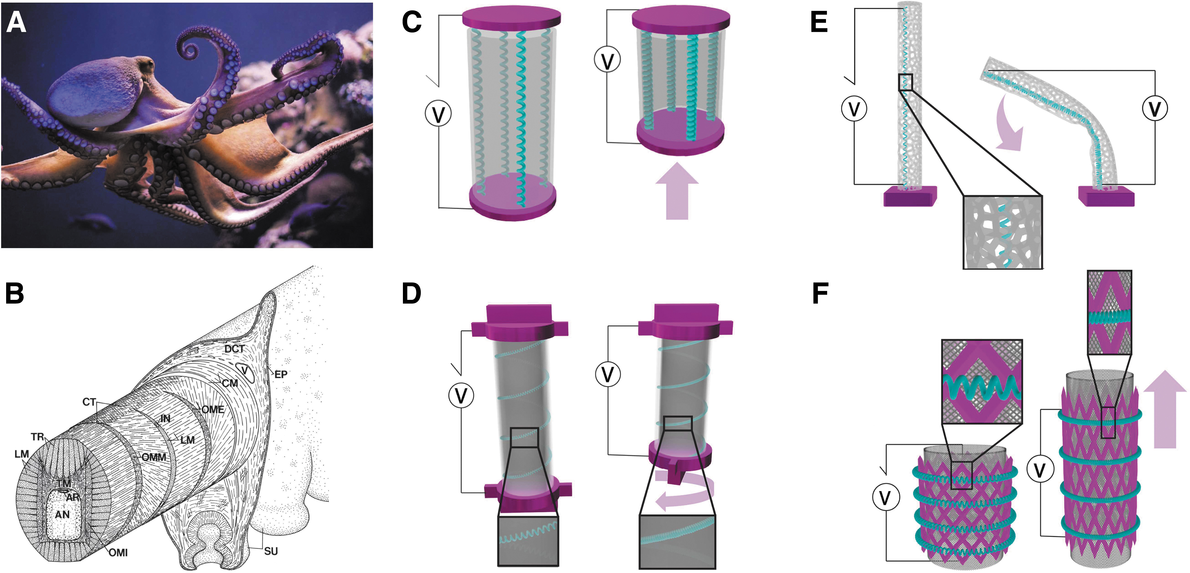
Bioinspiration and TCAM arrangement for the proposed hydrostats.
The capabilities of the octopodes' arms are derived from a unique muscular arrangement referred to as muscular hydrostats. 15 Muscular hydrostats are biomechanical systems comprising muscle and soft tissues, which lack rigid skeletal support for the muscles to act upon. In octopodes' arms, muscular hydrostats are arranged as thin layers around an axial nerve cord (AN in Fig. 1B). 7 In each layer, tightly packed muscle fibers are oriented in different directions, namely: longitudinal muscles (LM), transverse muscles (TM), and internal, external, and medial oblique muscles (OMI, OME, and OMM, respectively) as depicted in Figure 1B. The activation of one or more of these muscle fibers drives the four primary motions of octopodes' arm: shortening, torsion, bending, and extension. Several successful designs such as the OCTOPUS Integrating Project, 16 the OctArm manipulator,17,18 and the STIFFness controllable Flexible and Learnable manipulator for surgical operations 19 have been proposed to achieve the range of motion of octopodes' arms.
However, these designs employ conventional actuator technologies such as pneumatic actuators, cable-driven systems, and electrical motors that still present the main limitations of traditional robots in terms of low power/weight ratios and compliance. Therefore, there is a strong need for new actuator technologies that can generate large power/weight ratios within a soft and compliant structure.
Artificial muscles are a new breed of lightweight actuators with a high power/weight ratio that have captured the attention of scientists for soft robotic applications.20–23 We explored the benefits and shortcomings of the different classes of artificial muscles in a previous work. 21 Unlike multicomponent conventional actuators, artificial muscles can reversibly contract, expand, or rotate within one single component when excited by an external input. 21
With regard to muscular hydrostats inspired by octopodes' arms, researchers have employed artificial muscles such as shape-memory alloys (SMAs),22–25 dielectric elastomers (DEs),26–28 and McKibben actuators for driving soft robotic manipulators.29–32 However, these artificial muscles present significant limitations: McKibben actuators show high-power density, speed, and high strain values but need heavy and noisy air compressors for actuation; 33 SMAs can generate high stress values but they are expensive, difficult to control, and exhibit significant hysteresis during contraction; 34 DEs exhibit high strain values but they require high voltages (kilo-megavolt range) and prestraining for their operation. 35
In this work we propose octopus-inspired muscular hydrostats powered by an emerging class of artificial muscles called twisted and coiled artificial muscles (TCAMs) (Supplementary Movie S1).36–40 TCAMs are fabricated by twisting and coiling inexpensive fibers, can sustain stresses up to 60 MPa, and provide tensile strokes of nearly 50% with <0.2 V/cm of input voltage. 41 Additionally, we recently demonstrated that TCAMs can provide the same active and passive force profile of skeletal muscles within one single component. 42 We have also performed cyclic testing of nylon 6 TCAMs in a range of environmental conditions with the TCAMs demonstrating less than a 1% change in stroke length over 5000 cycles while maintaining their ability to withstand a consistent stress with a constant response rate with a 2.2-s activation time and a 46.2-s cooling period. These performances overcome the limitations of SMAs, McKibben, DEs, and other artificial muscles in terms of cost, power, and portability, 43 and lead to the development of truly bioinspired muscular hydrostats.
Four different configurations of muscular hydrostats with TCAMs arranged in different orientations are designed in this work for emulating the four main behaviors of octopodes' arms: shortening (Fig. 1C), torsion (Fig. 1D), bending (Fig. 1E), and extension (Fig. 1F). This work represents the first step toward the development of a lightweight octopus-inspired soft tentacle that can exhibit a large repertoire of complex movements.
Results and Discussion
Contraction muscular hydrostat
In octopodes' arms, muscles (LM in Fig. 1B) that drive the shortening mechanism are oriented parallel to the longitudinal axis of the arm. 7 The contraction hydrostat (CH) used for emulating the shortening mechanism of octopodes' arms is depicted in the schematic of Figures 1C and 2A. The CH consists of four TCAMs attached to two three-dimensional (3D) printed holders and wrapped with a thin silicone sheet. The total weight of the device is 99 g.

CH and working principle of TCAMs.
Figure 2B and C depicts the CH before and after TCAM actuation, respectively. A maximum contraction of 40% is depicted in Figure 2C and Supplementary Movie S2.
The shortening of the CH is derived directly from the radial expansion of TCAMs. The TCAM actuation can be directly related to the geometry, loading conditions, and mechanical properties of the TCAM materials with simple mechanical models we developed (Supplementary Data for details).44–47 TCAMs are fabricated by overtwisting Nylon 6 fishing lines under a tensile load until spontaneous coiling (Fig. 2D). In this work, we fabricated TCAMs using an automated twister setup (Fig. S1 in Supplementary Data for details) and electrothermally actuated using a direct current power supply through a microcontroller and transistor (Fig. S2 in Supplementary Data). The plot in Figure 2E depicts the validation of our electrothermal model, while Figure 2F shows validation of the dynamic model for the CH displacement.
Torsional muscular hydrostat
Limb torsion is achieved by the octopus through alternating layers of muscle fibers arranged obliquely to the axial nerve core (OMI, OME, and OMM fibers in Fig. 1B). 7 In our soft robotic analog (Fig. 3A) we replicate the AN with a silicone gel core with 3D printed caps at the ends serving as attachment points for the associated TCAM. The TCAM is helically wound around the gel core and secured tightly along the entire length of the hydrostat by an outer skin of silicone elastomer. The proximal cap is used to mount the device to a frame for suspension and 2N of pretension is applied to the TCAM at the distal cap. The combined device weight is 38 g and can demonstrate a maximum twist of 75° in current iterations (Fig. 3B; Supplementary Movie S3). The direction of motion is determined by the direction of twist insertion into the muscle during manufacturing, and the magnitude of the rotation can be maximized by matching this twist direction with the direction of muscle wrapping around the central core. Details of the hydrostat showing the layered arrangement of the core, TCAM, and skin can be seen in Figure 3C.

TH with theoretical model.
We developed a theoretical model to predict the angle of twist achieved by the torsional hydrostat (TH) device, which is dictated by the geometric properties of the TCAM and the gel core. The central gel core mimics the AN of the in vivo octopus' limb, and we treat its behavior as a hyperelastic solid rod operating within a linear elastic region. The torsion angle of a linear elastic solid rod can be written as follows:
where α is the angular deflection of the shaft in radians, L is the length of the shaft, T is the applied external torque, J the polar moment of inertia of the shaft, and G is the shear modulus of the shaft.
The shear modulus of the gel core was determined using a torsion pendulum test with the onboard sensors of a smartphone acting as a pendulum bob and recording the period of the damped oscillation of the pendulum (Fig. S3 in Supplementary Data). As described earlier, actuation of the TCAM occurs because of the radial expansion of the precursor fiber, which drives the internal untwisting of the fiber as it stiffens and reaches its new equilibrium coil configuration by contracting. This mechanism of TCAM actuation imparts torsion to the TH with two different contributions: a torsion coming from the TCAM untwisting and a torsion coming from the TCAM contraction.
The first and dominant contribution is from the untwisting of the TCAM fiber as it is heated and radially expands. The gel core has a highly tacky surface, which enables transfer of the untwisting moment from the fiber to the core when the fiber is held tightly against it by the outer skin (Fig. 3C, D). This untwisting moment generates a torque on the gel core that contributes to the torsional motion of the cylinder. The angle of rotation contribution of the untwisting moment of the TCAM is then given by:
Where
In this way, the direction of rotation for the overall cylinder is determined by the direction of twist inserted into the artificial muscle during manufacturing. If the fiber is twisted in the clockwise (cw) direction during manufacturing, then upon heating the fiber untwists in the counterclockwise (ccw) direction. This ccw rotation held against the compliant gel core causes the cw rotation of the entire device due to the high friction between the TCAM and the gel core. The magnitude of rotation can be maximized by matching the direction of twisting of the muscle with the direction of winding of the muscle around the gel core and is reduced when the winding and twisting directions are opposed. This effect occurs because of the second twisting motion imposed by the TCAM.
The second component of motion occurs as a result of the linear contraction of the TCAM upon actuation (Fig. 3E). Helical winding of the actuator around the gel core means that a linear shortening of the muscle acts to draw the termini of the device closer together following the helical path. The shortening of the TCAM can be calculated using our theoretical models we developed previously.
38
The contractile contribution to the overall torsion in the cylinder is then given by:
To isolate the two components, we manufactured two distinct types of actuators for testing: standard TCAMs, which are twisted until spontaneous coil formation occurs and twisted artificial muscles (TAMs), which are twisted up to the point of coil initiation. TAMs will undergo an untwisting moment without the linear displacement or shortening associated with the coiled geometry. We manufactured six TCAMs and six TAMs to attain the same final actuator length and used these to construct 12 test cylinders (Fig. S4 in Supplementary Data for details). All actuators were manufactured with cw twist inserted and then half of each was wound cw around the gel cores, while the remaining actuators were wound ccw around the remaining gel cores. The test validation cylinders then comprise three samples each across four cases as shown in Table 1. As previously noted, the magnitude of the twist is maximized when the directions of TCAM twisting and winding around the gel core are matched and minimized when the directions are opposed.
Four Cases for Torsion Model Validation Testing
TAM, twisted artificial muscle; TCAM, twisted and coiled artificial muscle.
From the two actuator types and directions of twist we have four cases as shown in the right-most column of Table 1. Plots for validating the theoretical model for the TCAMs and TAMs are displayed on the left and right of Figure 3G, respectively.
Bending muscular hydrostat
In octopodes' arms, bending is achieved through selective contraction of LM fibers along one side of the arm in combination with activation of TM fibers that resist longitudinal shortening. 7 To maximize bending actuation and minimize the number of TCAMs in our bending hydrostat (BH), we exploited mechanical instabilities to convert the contraction of a single TCAM into a bending motion (Fig. 4A). The device is designed by applying a Voronoi tessellation algorithm 48 to a primitive cylinder with a diameter of 2 cm and a length of 17.5 cm. We tailored the density of Voronoi cells in the primitive cylinder to allow for nonuniform topological distribution of the lattice points for controlled bending. The Voronoi cells were distributed with decreasing density toward the center of the cylinder along the radial direction to ensure muscle contraction was converted into bending instead of pure shortening (Fig. 4B, C).

Images, actuation, and FE simulations of BH.
The BH was fabricated through a stereolithography technique using a flexible photopolymer resin. A single TCAM attached to the Voronoi cylinder through 3D printed holders and eyebolts was used to initiate bending. The total weight of the BH was 27 g.
Hydrostat bending depicted in Figure 4D is achieved by actuating the TCAM using an input power of 10W for 3 s. A maximum bend of 72° is depicted in Figure 4D and Supplementary Movie S4. Finite element (FE) simulations were done to optimize the Voronoi cylinder geometry for maximizing the cylinder bend as shown in Figure 4E. The beam thickness (BT) of the Voronoi cylinder and the density distribution (DR) of the Voronoi cells were the main driving factors for maximizing bending (Fig. 4F). The bending angle increased with an increase in both density ratio and BT. Therefore, a maximum DR of 10 along both the axial and radial directions was implemented for the BH. However, a BT of 2 mm rather than the maximum of 3 mm highlighted in Figure 4F was chosen for the Voronoi cells. Displacement-controlled FE simulations were carried out to simulate the contraction of the TCAM. Therefore, although the simulations point to a BT of 3 mm with a DR of 10 as the ideal configuration for the BH, in the actual prototype the force generated by the TCAM was not enough to overcome the stiffness of the 3 mm cylinder.
Extension muscular hydrostat
Limb extension is achieved by octopodes through the selective contraction of TM fibers along its length. 7 In accordance with the isovolumetric nature of the arm, any decrease in the cross-sectional area will result in an extension of the limb with the magnitude of the limb extension dictated by the degree of contraction of the TM fibers as well as the number recruited along the length of the limb. This selective contraction can be highly localized for fine control and positioning of the limb.
In the proposed extension hydrostat (EH), circumferentially arranged TCAMs have been preferred over radially arranged TCAMs to develop a more compact device with a small number of actuators and with an empty core, which will foster the assembly of different muscular hydrostat layers for soft tentacles.
In our hydrostat, we achieve elongation using a combination of the circumferentially arranged TCAMs and a composite mesh array with a large Poisson's ratio. In our EH design, circumferential TCAMs contract to impinge upon the composite mesh array, which then converts the radial compression into an axial elongation. The composite mesh array comprises a polyethylene terephthalate (PET) braided sleeve with a coating of silicone elastomer and a red silicone mesh (Fig. 5A, B). The unit cell of the red silicone mesh consists of struts with a deformable hinge that allows extension of the cell when a radial contraction is applied (Fig. 5C, D). The silicone mesh serves the primary purpose of uniformly distributing the load generated by the TCAMs across the entire length of the braided sleeve, thereby minimizing the number of TCAMs needed for extension (Fig. S5 in Supplementary Data for details). For our EH, we “froze” the sleeve in its compressed state with an initial braid angle of 90° using a thin layer of silicone elastomer (Fig. 5E; Fig. S6 in Supplementary Data) to convert a radial compression to an axial extension. The total weight of the EH was 58 g.

Images, actuation, and FE simulations of extension muscular hydrostat.
An extension of 2.2 cm (18.3%) is achieved by actuating the TCAMs using an input power of 40W for 6 s (Fig. 5C; Supplementary Movie S5). We also performed a displacement-controlled FE simulation to optimize the geometry of the red silicone mesh for maximizing hydrostat extension and minimizing the number of TCAMs needed for actuation (Fig. 5F). We modeled the PET braided sleeving with the elastomer coating as a composite lamina with equivalent material properties of the two components. Unit cells with a maximum included angle (ø) of 140°, which translates to a completely open cell before TCAM actuation, caused maximum extension (Fig. 5G). Additionally, since the load applied by the TCAM is transferred to the braided sleeve through the red silicone mesh, the thickness of the mesh was an important parameter for maximizing the extension. Like the FE simulation for the BH, we simulated the TCAM contraction as a displacement applied to the hinges of the silicone mesh. Therefore, although the FE simulations underscored an increase in extension with an increase in mesh thickness, the red mesh was fabricated with a thickness of 3 mm (Fig. 5G).
Meshes with higher thickness values (5 and 7 mm) were too stiff for the TCAMs used to provide a desired contraction.
Control and underwater actuation of TCAM-powered hydrostats
In this study we used a previously developed

Angle/displacement measurement of each muscular hydrostat. Camera detection markers for the
Figure 7A and B, and Figure S8 in Supplementary Data show the untethered waterproof hardware system used for underwater control and actuation of the hydrostats. The hardware system comprises a microcontroller that sends the Pulse width modulation voltage signal for the electrothermal actuation of the TCAM from a Raspberry Pi microprocessor through a power electronic circuit coupled with a Darlington pair transistor (Fig. 7B). The microcontroller is connected to the microprocessor through a universal serial bus hub and powered using a 5V rechargeable battery. A 14.8V Lithium Polymer battery pack provides the power required for actuating the TCAM. The actuation of the CH and BH is shown in Figure 7C and D, respectively.

Control and underwater actuation of hydrostats.
The implementation of our

Displacement/Angle tracking for muscular hydrostats using the adaptive controller. CH angle tracking in
Rube Goldberg obstacle course
To demonstrate the combined actuation of all the devices underwater, we constructed a subaquatic obstacle course for the different configurations to manipulate a glass marble through. The hydrostat prototypes are powered by Nylon 6 TCAMs, waterproofed using flexible tubes (Fig. S9 in Supplementary Data). The course itself is constructed from an aluminum T-channel frame with 3D printed obstacles attached. The four hydrostat devices are mounted in place to the frame, and a custom-built control circuit utilizing an Arduino Uno microcontroller is wired into the devices and mounted to the frame for actuation.
The marble begins atop the EH at rest (Fig. 9A). Actuation of the EH causes the marble to roll down the first ramp until it is blocked by a swing arm attached to the distal cap of the torsion device (Fig. 9B). The TH is actuated to rotate the blockade, allowing the marble to continue down the ramp into the basket on the base of the compression hydrostat (Fig. 9C). The CH for this case has the TCAMs wired in two sets, a front and a back, which allow the basket to rise when actuated in tandem and tilt when actuated individually. The marble then rolls into its final position where the BH is actuated.

Rube Goldberg underwater obstacle course demonstration.
A pin attached to the tip of the BH closes the circuit powering an light emitting diode lamp and illuminates the chest as illustrated in Figure 9D and E. Inset photos Figure 9F–I provide enlarged views of the hydrostat–marble interactions with the extension and contraction devices, respectively. All images are screenshots from the demonstration video provided in Supplementary Movie S6.
Conclusions
Inspired by the musculature of the arms of octopodes, we designed muscular hydrostats powered by bioinspired actuators called TCAMs. Four different muscular hydrostats that exhibit the primary motions of octopodes' arms, that is, shortening, torsion, bending, and elongation are designed and fabricated by altering the orientation and arrangement of TCAMs. The CH is solely driven by the anisotropic volume expansion of electrothermally actuated TCAMs and demonstrated a maximum compression of 40%. For the torsion hydrostat, the helical arrangement of a single TCAM around a compliant core converts TCAM contraction into a torsional motion. A maximum twist of 75° was achieved using the TH. Additionally, we described the motion of the torsion hydrostat using a theoretical model that considers both the untwisting moment and contraction of the obliquely oriented TCAM. For the BH and EH, to convert the contraction of the TCAM into a different degree of freedom we employed mechanical instabilities and anisotropic material properties of compliant materials, respectively.
The BH utilized mechanical instabilities generated by localized distribution of Voronoi cells to convert TCAM contraction into a maximum localized bending of 72°. The EH exploited the large Poisson's ratio of braided cable sleeving and a specially designed compliant mesh to transform TCAM contraction into a maximum elongation of 18.3%. The weight of the CH, TH, BH, and EH is only 99, 38, 27, and 58 g, respectively.
All the developed muscular hydrostats can be independently actuated or assembled to develop waterproof soft robots with potentially infinite degrees of freedom. Future steps involve the development of these individual hydrostats into unit cell-based structures to achieve multimodal motion while preventing interference from each other. In addition, we are investigating the interplay between contraction and extension as an alternative route to achieve bending without requiring the structural support provided by the current Voronoi hydrostat. Like the muscle fibers in the arms of octopodes, our TCAMs can exhibit motion within one single component and are manufactured from inexpensive polymer fibers using a simple low-cost fabrication technique we developed. As a first step toward the development of an integrated system, we also assembled a completely untethered waterproof device with on-board control, sensing, actuation, and a power source for driving our hydrostats underwater. We used an
Last, we built a Rube Goldberg setup that deploys the four hydrostats in-tandem in an underwater setting. This demonstration was the first step in addressing the challenging future work of combining the four different hydrostats in a single modular structure for truly emulating the repertoire of movements of octopodes' arms. This work opens the door to the development of compliant and truly bioinspired robots that can be used to explore the underwater world and perform complex tasks in harsh and dangerous environments.
Footnotes
Authors' Contributions
P.K., S.M., and C.L. conceived the idea and designed the experiments. P.K. and S.M. manufactured and modeled the hydrostats. T.W. developed the control algorithm and untethered power unit for the hydrostats. P.K., S.M., and T.W. designed and manufactured the Rube Goldberg setup. V.C. supervised the development and implementation of the control algorithm. All authors contributed to writing the article. C.L. supervised the research.
Author Disclosure Statement
No competing financial interests exist.
Funding Information
Funding for this study was received from the Defense Advanced Research Projects Agency Young Faculty Award grant W911NF2110344-0011679424 (C.L.); Office of Naval Research Young Investigator Program grant N00014-23-1-2116 (C.L.); and the Iowa NASA Established Program to Stimulate Competitive Research subaward 025372A from the Iowa State University (C.L.).
References
Supplementary Material
Please find the following supplemental material available below.
For Open Access articles published under a Creative Commons License, all supplemental material carries the same license as the article it is associated with.
For non-Open Access articles published, all supplemental material carries a non-exclusive license, and permission requests for re-use of supplemental material or any part of supplemental material shall be sent directly to the copyright owner as specified in the copyright notice associated with the article.