




Abstract
The field of soft robotics is rapidly evolving, and there is a growing interest in developing soft robots with bioinspired features for use in various applications. This research presented the design and development of 3D-printed origami actuators for a soft robot with amphibious locomotion and tongue hunting capabilities. Two different types of programmable origami actuators were designed and manufactured, namely Z-shaped and twist tower actuators. In addition, two actuator variations were developed based on the Z-shaped actuator, including the pelvic fin and the coiling/uncoiling types. The Z-shaped actuators were used for the rear legs to facilitate the locomotion of the water-like frogs. Meanwhile, the twisted tower actuators were used for the rotation joints in the forelegs and for locomotion on land. The pelvic fin actuator was developed to imitate the land locomotion of the mudskipper, and the coiling/uncoiling actuator was designed for tongue hunting motion. The origami actuators and soft robot prototype were tested through a series of experiments, which showed that the robot was capable of efficiently moving in water and on land and performing tongue hunting motions. Our results demonstrate the effectiveness of these actuators in producing the desired motions and provide insights into the potential of applying 3D-printed origami actuators in the development of soft robots with bioinspired features.
Introduction
Over millions of years, organisms have evolved almost perfect limbs and organs capable of adapting to nature environment. Scholars hope to create highly innovative designs and sophisticated technology in engineering by studying the locomotion of living things. The traditional rigid bioinspired robots have been designed with more mechanical structures, 1 which are more complex and bulkier in a bioinspired sense and do not fit the characteristics of living things. The rise of soft robots in recent years has promoted the development of bioinspired robots, which are endowed with different lifelike characteristics due to the soft material properties and novel actuating technology. Currently, many bioinspired soft robots for use in water are being developed, inspired by jellyfish, 2 deep-sea snail fish, 3 frog, 4 octopus suckers, 5 and others, and soft robots inspired by terrestrial reptilian creatures, including earthworm, 6 crab, 7 snake, 8 and lizard. 9
However, the structures or propulsion methods of these robots can only be adapted to specific environments, regardless of whether they are water or land robots, and an amphibious bioinspired soft robot is challenging to develop.
Amphibians, a class of creatures that have the ability to swim in water and walk on land, offer biological inspiration for a robotic design. Bioinspired soft amphibian robots are always imitating the locomotion and posture of animals. 10 In these studies, the propulsive methods of amphibious robot can be divided into independent and hybrid actuator propulsion methods. Bioinspired robots that use the independent actuator propulsion method are as follows: looper, 11 sea urchin, 12 dog, 13 starfish, 14 tortoise, 15 and lizard, 16 and the propulsion of these robots is similar on land and in water. Although these robots can achieve high efficiency on land, their performance in water is much less than that on land due to the influence of resistance in water. Robots that use hybrid actuator propulsion include EELWORM (inspired by eel and worm), 17 a combination of insect crawling and human swimming postures, 18 a seal, 19 and a combination of turtle and tortoise locomotion postures. 20
These robots use multiple actuators and are inspired by multiple biological locomotor modalities. Researchers have taken the locomotor advantages of the various types of organisms and integrated them in one robot, thus greatly increasing the locomotor performance of robots on land and water and enhancing their more integrated locomotor capabilities. However, the problem is that making multiple actuators in different environments without affecting each other is difficult. Specifically, how the robot is actuated in water and on land is difficult to coordinate.
Origami, as an ancient art of paper folding, has received increasing scholarly attention. Origami structures have inspired new approaches to soft robot design, 21 and many soft origami robots are currently designed based on the following four typical origami structures: Miura origami,22–24 water bomb origami,25–27 Yoshimura origami,28–30 and Kresling origami.31–33 A complex output can be obtained from a simple input by means of an ingenious origami structure. In fact, the versatility of origami structures combined with the properties of soft materials can bring out the advantages of both, and soft origami can traverse some unstructured areas by folding and assembling itself. 34 In previous studies, the modular design of multiple actuators has great advantages for repairing systems, replacing and reconfiguring modules, 35 and self-transformation of various shapes and geometries. 36 Accordingly, research on the cooperative motion of multiple origami actuators has great potential.
However, despite that single origami structures have been intensively studied, the integration of different patterns of origami actuators is rare. 18 There are fewer examples of research where origami mechanisms may be used in bioinspired robots, and it is underresearched how to combine origami modules with various types to achieve multimodal locomotion of bioinspired soft robots.
This work designed a novel bioinspired amphibian soft robot that integrates the following four origami actuators: Z-shaped, twisted tower, pelvic fin, and coiled/uncoiled origami (Fig. 1A). The motion mechanisms of frog swimming, mudskipper crawling, and frog hunting are observed and analyzed. The result showed that the motion trajectories of the Miura and Kresling origamis could be made to fit the animal's limbs, joints, and organs by a clever design. The four origami actuators are directly 3D printed from a thermoplastic elastomer (TPE) through fused deposition modeling and heat-treated to withstand a high fluid pressure. The motion characteristics of the bioinspired amphibious soft robot can be well characterized with a designed pneumatic hardware control system.

Application scenarios and multianimal bioinspiration of the proposed amphibious soft robot.
The robot is actuated by six air paths, which can realize the combined functions of nine different modes (straight/left/right swim, straight crawl/alternate/left/right/back crawl, tongue hunting). The insect catching function can be achieved by relying on the coiled/uncoiled origami actuator (C/UOA) (frog tongue), maximum swimming speed of 0.6 body length per second (BL/s), and turning speed of 10.7°s−1 in water for the robot moving by Z-shaped origami actuators (ZSOAs) (frog legs), combination of twist tower origami actuators (TTOAs) (pectoral fin joint of mudskipper) and pelvic fin origami actuator (PFOA) (pelvic fin of mudskipper), the robot moving with a maximum land crawling speed of up to 20.6 mm/s, and a turning speed of 30° s−1 on land. Meanwhile, the crawling robot can withstand heavy objects of the same weight as itself and can crawl through different terrains, highlighting its ability to move in unstructured environments.
Furthermore, the ability to transition between different environments is an important index for amphibious robots, and a robot with the ability to cross-medium not only from land to water but also from water to land is designed. The application scenario of the robot is also described in Figure 1B.
The main contributions of this article include the following three points: (1) four 3D-printed origami actuators with different morphologies are designed by combining the origami and biological motion mechanisms from two different creatures; (2) programmable motion modes of the origami actuators are evaluated; and (3) the amphibious cross-medium locomotion of a multianimal-inspired soft robot based on origami actuators is realized.
Analysis of Origami Actuators
Structure design and kinematic analysis of ZSOA
Inspiration from Miura origami
The Miura origami method facilitates rapid folding of a paper sheet into multiple origami units, as depicted in Figure 2A. Inspired by Miura origami, we alter the length of the initial origami units to mimic the locomotion of frog leg in water and arranging them to form a Z-shaped structure resembling the tubular configuration proposed by Tachi and Miura 37 and used 3D printing technology for the fabrication of ZSOAs. In comparison with Kim et al.'s bioinspired dual-morphing stretchable origami, 22 our ZSOA exhibits a simplified fabrication process, and moreover, a frog-like swimming locomotion pattern that is discussed in detail in the following section.

Design of ZSOA.
Actuation mechanism and parameters of ZSOA
The actuator comprises three flexible channels, each capable of being assigned a distinct length. The interior of the actuator consists of a homogeneous gas channel, and programmable motion is achieved by incrementing positive pressure P. The channel is systematically unfolded in accordance with the prescribed design rules, as demonstrated in Supplementary Movie S1, which illustrates the conceptualization of ZSOA. The length of the actuator is denoted as L, the width as W1, the wall thickness as t1, the length of the three flexible channels as c1, c2, and c3, and the width tilt angle of the double layer flexible cavity as α. For the parameter configuration of ZSOA, refer to Table S1 in Supplementary Data.
Kinematic analysis of ZSOA
To investigate the kinematics of the actuator in programmable mode, a series of experimental comparisons were conducted under various parameters, as illustrated in Figure 2B. Groups 1a, 1b, and 1c modulate the length of the flexible channel, and with increasing pressure, the two double layer flexible cavities adjacent to the longer channel consistently unfold preferentially. This phenomenon may be attributed to a proportional relationship between the expansion rates of its inner surface. By adjusting the channel lengths, precise control over the motion trajectory of the actuator can be achieved. Groups 1a, 2a, and 2b manipulate the actuator's length, resulting in an increased range of motion that ultimately expands its movement capabilities. The actuator width is modified by Groups 1a, 3a, and 3b, with the degree of deformation being directly proportional to the actuator width.
This relationship may be attributed to the increased cross-sectional stiffness of the material at smaller widths, resulting in reduced elastic deformation when pressure is applied. Groups 1a, 4a, and 4b alter the tilt angle of the actuator, and the magnitude of this tilt angle can impact its deformability within the flow channel. When subjected to identical air pressure conditions, a smaller tilt angle poses greater challenges for achieving substantial deformation in the actuator. The wall thickness of the actuator is altered by Groups 1a, 5a, and 5b. It becomes evident that an actuator with increased wall thickness necessitates higher driving pressure due to the enhanced stiffness resulting from thicker materials, which in turn affects its response speed.
These can be observed in Figure 2C where both experimental and simulated actuator motion trajectories are clearly depicted. Simulation results are depicted in Figure S1 of Supplementary Data. The related experiments are shown in Supplementary Movie S2.
Variation actuators from Z-shaped origami
The Z-shaped origami, inspired by the Miura origami serves as a foundation for the development of various intriguing origami structures. Two types of actuators, the pelvic fin origami and the coiling/uncoiling origami, are derived from Z-shaped origami, as shown in Figure 3A, namely PFOA and C/UOA based on the shape of the origami paper. The initial state of PFOA is inwardly curved, enabling expansion through applied pressure. A comparison between experimental and simulated trajectories with four different parameters is illustrated in Figure 3B. C/UOA is a type of internally wound actuator. If the thickness of a specific plane within the actuator is altered, its unfolding trajectories will be offset during the actuation process. The motion trajectories can be observed in Figure 3C.

Variation actuators of Z-shaped origami.
The simulation results are depicted in Figure S2 of Supplementary Data, and the different parameter configurations of PFOA and C/UOA can be referred to Tables S3 and S4 in Supplementary Data.
Structure design and kinematic analysis of TTOA
Inspiration from Kresling origami
Kresling origami is an origami with a torsional motion that occurs through a preset diagonal crease. Figure 4A shows our design idea of a TTOA. Most current studies based on Kresling origami are conventional with a square hexagonal cross section,31,38–42 which can be twisted at an angle of 60° (360°/side length) in the ideal state (without considering the wall thickness). However, if a Kresling origami structure with a square cross section is designed, then the twistable angle in an ideal state is 90°, which can be twisted at a larger angle compared with the Kresling origami with a hexagonal cross section. Accordingly, a twisted tower origami was designed on the basis of the principle of traditional Kresling, and a TTOA was fabricated by 3D printing. The design idea of the TTOA can be viewed in Supplementary Movie S3.

Design of twist tower origami actuator.
Actuation mechanism of TTOA
The thickness of the top and bottom surfaces of the TTOA was greater than the thickness of four walls (during actuation, the top and bottom surfaces are stiffer than the four walls, making the actuator easier to compress), and a through-hole was designed at the bottom of the actuator to connect to the air tube, allowing the actuator to achieve a dual degree-of-freedom motion: contraction and torsion, driven by vacuum pressure −P. Unlike the vacuum-powered soft pneumatic actuator designed by Jin et al., 32 they achieved torsion by designing crease grooves in the four walls, which greatly increased the thickness of four walls of the actuator, correspondingly increasing the overall size of the actuator. However, the TTOA was designed with a preset tilt angle to achieve torsion, which not only reduced the 3D printing wall thickness material but also made the actuator highly compact. This actuator also exhibited bistability (movement from one stable state to another).
Parameters of TTOA
The square bottom side length of the TTOA, height, internal cavity height, four-wall thickness, and four-wall preset tilt angle were denoted as W2, H, h, t2, and β. When negative pressure actuation was performed, the height displacement of the actuator was ΔH, the contraction ratio was δ = ΔH/H, and the torsion angle was ϕ. Variation of the contraction ratio and torsion angle of the TTOA was investigated by setting the different parameters (Table S2 in Supplementary Data).
Kinematic analysis of TTOA
To investigate the kinematic characteristics of contraction and torsion in TTOA during driving, four actuator sets with different parameters were compared, and the results are presented in Figure 4B. Groups 6a, 6b, and 6c alter the length of the actuator's bottom edge. Under identical air pressure, an increase in the actuator's side length results in a higher contraction ratio. However, augmenting the bottom edge length (Groups 6a, 6b, and 6c) leads to a decrease in torsion angle. The transition between two stable states of this actuator occurs during “snap-through,” which refers to its shift from one stable state to another within an unstable structure at vacuum pressures mostly between −20 and −40 kPa (shaded gray region in Figure 4C).
The actuator's torque angle increment exhibited a small change with the increase in height for Groups 6a, 7a, and 7b, however, there was a significant reduction in contraction. The actuator's preset inclination angle is altered in Groups 6a, 8a, and 8b. Increasing the inclination angle enhances the initial state of the actuator's side wall fit, resulting in a narrower internal space, and this leads to a reduction in the folding rate of the wall, thereby decreasing both torsion angle and contraction magnitude. Interestingly, this adjustment promotes greater stability during the transition process between two steady states of the actuator while diminishing the prominence of “snap-through” phenomenon. Groups 6a, 9a, and 9b alter the thickness of the actuator's side wall, and an increase in wall thickness results in a delayed “snap-through” phenomenon, thereby reducing the response speed of the actuator. The comparison between the experimental and simulation results of the contraction ratio and torsion angle is illustrated in Figure 4C. The simulation details are provided in Figure S3 of Supplementary Data. The related experiments are presented in Supplementary Movie S4.
Analysis of Bionic Structure and Locomotion Mechanism of the Proposed Robot
Overall structure of the proposed robot
Figure 5A shows the overall structure of the herein designed robot with four origami actuators integrated into one robot body: (1) A C/UOA mounted on the head of robot; (2) the forelimb is assembled from the joint connector, TTOA, shoulder connector, and forelimb component; (3) the hind limb is modularly designed with ZSOA, foot component, and web component; and (4) the bottom of the robot is installed with a PFOA. Detailed information about the robot structure, Note S1 in Supplementary Data.

Design and analysis of frog-like leg actuator.
Design and analysis of the frog-like leg actuator
Swimming mechanism of frog
By observing freshwater frogs, we have identified their distinctive swimming patterns: expansion, propulsion, and recovery,43,44 as shown in Figure 5B. During the expansion stage, the knee joint between the frog's thigh and calf is preferentially activated to adjust the position of limbs for a maximum range of webbed beating on water. In the propulsion stage, rapid activation of ankle and hip joints generates paddling force on water surface to promote frog swimming movement, utilizing inertia from this force, enabling gliding movement on water surface. Finally, during the recovery stage, all three joints of frog's legs are activated to return to the initial swimming position.
Parameter selection of ZSOA
Our objective is to develop a frog-like leg actuator by using ZSOA kinematic analysis and incorporating the mechanism of frog swimming locomotion. Consequently, we conducted tests to examine variations in joint angles during both the expansion and propulsion stages, defining the angles at the hip, knee, and ankle as θhip-F, θknee-F, and θankle-F. As shown in Figure 5C, the knee joint exhibits the most rapid increase in angle throughout the entire motion cycle, indicating its early activation. Moreover, θknee-F eventually approaches 140°, while the ankle angle is slightly smaller than that of knee, with θankle-F tending toward 50°. The variation in joint angle of the frog during locomotion is illustrated in Figure S5 of Supplementary Data. Based on these experimental findings, we select ZSOA parameters.
The kinematic analysis reveals that the length of actuator channel is directly proportional to the expansion speed of flexible cavity. Therefore, the parameter c2 of ZSOA is set to 12 mm, and this channel is used as the knee joint of frog. Similarly, c3 is set to 3 mm as the ankle joint, with the intention of ensuring a lower angular response speed compared with that of the knee joint. As for c1, it is set at 6 mm to represent the hip joint, this choice is motivated by observing that the hip joint angle response lags behind the knee joint angle response and ultimately reaches a development angle of 50°. The actuator length L is set to 80 mm and the tilt angle α is set to 90°, as increasing the range of motion will enhance the efficiency of water surface paddling.
In addition, considering both response speed and useful life, a wall thickness t1 of 1.2 mm is chosen for the actuator. The dimensional parameters of frog-like leg actuator are shown in Figure S4A of Supplementary Data.
Aquatic locomotion mechanism of the robot
The frog-like leg actuator is carefully chosen based on specific parameters, and an in-depth investigation is the leg driving trajectory of the aquatic locomotion mechanism used by the robot. The angular positions of the robot's hip, knee, and ankle joints were denoted as θhip-R, θknee-R, and θankle-R, respectively. Subsequently, the changes in joint angles for each component of the frog leg actuator were recorded under actuation pressure of 120 kPa. The initial state of the joint angle during the movement cycle is inconsistent, as depicted in Figure 5C, due to variations in the installation position of the imitation leg actuator on our designed robot compared with that of a frog's thigh. However, there exists a highly similar changing trend between the robot's joint angle and the frog's swimming motion, the maximum achievable values for all three joint angles closely resemble those observed in real frogs.
Furthermore, we conduct angular velocity tests on each joint of the robot and observed that at 1.75 s, the knee joint exhibited a peak angular velocity, surpassing both the ankle and hip joints. This finding provides further evidence supporting the activation sequence of the robot's knee joint aligning with the swimming characteristics observed in frogs.
The end trajectory of the frog leg actuator under driving conditions is depicted in Figure 5D. During the expansion stage (green line), a noticeable increase in x-axis trajectory indicates activation of the knee joint, leading to a rapid rise in θknee-R. Upon entering the propulsion stage (orange line), there is a sharp elevation in y-axis trajectory, signifying activation of both ankle and hip joints. Finally, during the recovery stage (blue line), the trajectory differs from that observed during propulsion, possibly due to the unique elastic resilience properties of the material. Moreover, the robot's webbed structure is designed to function unidirectionally, and during the propulsion stage, the webbed area maximizes contact with water, while in the recovery phase, it gets effortlessly washed away by the current. This design minimizes resistance during swimming and prevents any backward movement. Robot imitates frog swimming in Supplementary Movie S5.
Design and analysis of mudskipper-like joint and pelvic fin actuators
Crawling mechanism of mudskipper
The mudskipper, despite being an aquatic creature, possesses the capability to traverse terrestrial environments. The process of land crawling in mudskippers encompasses the following two distinct stages: propulsion and recovery. As shown in Figure 6A, in the propulsion stage, mudskippers rely on robust joints to torsion their pectoral fins, generating ground thrust and facilitating locomotion. In addition, the elongated pelvic fins located at the ventral side of their body provide auxiliary support to the pectoral fins, as some scholars propose that will enhance the generated thrust.45,46 During the recovery phase, the mudskipper elevates its pectoral fin back to the initial state without altering its body position.

Design and analysis of mudskipper-like joint and pelvic fin actuators.
Parameter selection of TTOA
One of this study's objectives is to develop an actuator that mimics the joint structure and crawling motion mechanism of mudskippers, utilizing the TTOA kinematic analysis method. Therefore, we conduct experimental analysis to investigate the torsion angle changes of mudskipper joints during both propulsion and recovery stages, denoted as θjoint-M (as illustrated in Fig. 6B, C). The obtained measurement data revealed that the maximum torsion angle of mudskipper joint is ∼70°. The snap-shots of mudskipper's joint angle changes are depicted in Figure S6 of Supplementary Data. Based on these data, we chose the parameters for TTOA. According to the maximum torsion angle of the mudskipper joint, the cavity height (h) of TTOA is set at 30 mm, and the preset tilt angle (β) is set to 85°.
To account for actuator volume and response speed, the bottom side length (W2) and wall thickness (t2) of the actuator are adjusted to 25 and 0.8 mm, respectively. The dimensional parameters of mudskipper-like joint actuator are shown in Figure S4B of Supplementary Data.
The torsion angle of the robot joint actuator is denoted as θjoint-R. Comparing it with the joint torsion angle of the mudskipper during propulsion and recovery, a highly similar trend between them as depicted in Figure 6B. The advancement of θjoint-R over θjoint-M can be attributed to the occurrence of the “snap-through” phenomenon induced by actuator actuating. However, in Figure 6C, the mudskipper in the recovery stage exhibits a rapid pectoral fin, leading to an in θjoint-M per unit time and causing it to significantly lag behind θjoint-R.
In summary, both movements tend to converge toward the same final limit value for joint angle, thereby inspiring the forward locomotion of our robot. In Figure 6C and D, the single-cycle displacement and turning angle of the robot were tested under different parameters (Groups 10a–10d) for the pelvic fin actuator. The Group 10a pelvic fin actuator demonstrates excellent backward ability when unactuated. When fully actuated (p = 100 kPa), the forward displacement caused by the Group 10a actuator is slightly lower than that of Group 10b. Consequently, augmenting the channel length (c4) of the pelvic fin actuator can enhance the robot's forward propulsion, however, significantly impeding its backward locomotion. In corner tests at an actuation pressure of 100 kPa, three actuators (Groups 10a, 10b, and 10c) exhibit good turning performance.
Consequently, considering combined capabilities in terms of forward motion, backward motion, and turning ability led to the choosing of pelvic fin actuator variant represented by Group 10a.
Parameter selection of PFOA
We aim to develop a pelvic fin actuator capable of enhancing the thrust generated by the joint actuator toward the ground, thereby augmenting the robot's terrestrial locomotion capabilities. In Figure 6D and E, pelvic fin actuators in Groups 10a–10b are compared. Considering the factors of the robot's forward, backward, and turning locomotion, the actuator Group 10a is selected. The dimensions for top surface (L1), bottom surface (L2), and channel (c4) are 29.7, 29.5, and 2.5 mm, respectively. The dimensional parameters of mudskipper-like pelvic fin actuator are shown in Figure S4C of Supplementary Data.
Terrestrial locomotion mechanism of the robot
The principle of the robot's terrestrial locomotion is devised by carefully selecting parameters for both the joint and pelvic fin actuators, as well as their coordinated actuation (Fig. 6A). The robot exhibits the following three modes of terrestrial locomotion: forward, turning, and backward. (1) During forward locomotion, the pelvic fin actuator remains actuated throughout, causing elevation of the lower end of the robot body. In the propulsion stage, two joint actuators are rotated to drive the pectoral fin actuators at their extremity, generating propulsive force on the ground and facilitating displacement of the robot by sliding the pelvic fin actuator. During the recovery stage, the joint actuators return to the initial state, while the pelvic fin actuator prevents the robot from moving backward due to its anisotropic friction.
(2) In turning locomotion, the underlying principle resembles forward motion and can be propelled by a solitary joint actuator. (3) In backward locomotion, the pelvic fin actuator remains unactuated throughout the entire motion process. During the propulsion stage of backward locomotion, joint actuator drives the pectoral fin actuator to generate ground resistance, resulting in an elevated robot body position without actual movement. Subsequently, in the recovery stage, backward locomotion is initiated by utilizing propulsion force generated through pectoral fin actuator recovery on the ground. The robot imitates the mudskipper crawling in Supplementary Movie S6.
Design and analysis of frog-like tongue actuator
Hunting mechanism of frog
During hunting, frogs typically exhibit two distinct states as follows: tongue projection and retraction. 47 As depicted in Figure 7A, the rapid rotation of the tongue is facilitated by robust muscles in the lower jaw during projection, enabling it to adhere mucus upon contact with the insect. When retracted, the tongue retrieves the insect to the mouth, restoring to its initial state.

Design and analysis of frog-like tongue actuator.
Parameter selection of C/UOA
Based on the analysis of frog hunting data from the video, we observe that the velocity during projection is significantly higher than retraction. Furthermore, the acceleration variation of tongue during projection is more obvious than retraction, as illustrated in Figure 7B. The trajectory of the frog's tongue during predation is depicted in Figure S7 of Supplementary Data. To develop an actuator that mimics the frog tongue projection mechanism, the C/UOAs of Groups 11a–11d are used to evaluate its velocity and acceleration characteristics. Subsequently, the Group 11a actuator is chosen, with parameters t3, t4, and t5 set at 0.8 mm. The dimensional parameters of frog-like tongue actuator are shown in Figure S4D of Supplementary Data.
Hunting mechanism of the robot
Lin et al. designed a dielectric elastomeric fluid sensor-driven bionic soft proboscis actuator, for coiling and uncoiling motions at an external voltage, but it is complex to fabricate and requires an external high-voltage power supply. 48 The frog-like tongue actuator is positioned on the robot's head (Fig. 7A). During the projection stage, the actuator rapidly uncoils and adheres to the object using an adhesive tape at its tip. In the retraction stage, the elastic resilience of the material allows the actuator to retract and bring back the object into its body. In Figure 7C, D, we conduct tests on the velocity and acceleration of the designated point at the extremity of the actuator. Results show that the projection mechanism is completed by the Group 11a actuator within a remarkable duration of 0.25 s, exhibiting a significantly superior speed compared with actuators with other parameters.
Furthermore, its acceleration reached a maximum value of 12 m/s−2, which closely aligns with the rapid projection mechanism observed in frog tongues and consequently influenced our selection of the 11a actuator. The robot imitating frog hunting is presented in Supplementary Movie S7.
Experiment on Robot Locomotion Capability
Hardware control system and gait of robot
Six distinct external air circuits are necessary for the robot's locomotion, which are regulated by six solenoid valves. In Figure 8A, Valves 4 and 5 correspond to joint actuators and receive negative pressure from a vacuum pump. Valves 1 and 2 correspond to leg actuators, Valve 3 corresponds to the pelvic fin actuator, and Valve 6 corresponds to the tongue actuator, which is supplied with positive pressure from a system with activation and deactivation of relay power to regulate the opening and closing of the air pathway. The hardware setup used for control is illustrated in Figure S8 of Supplementary Data.

Hardware control system and gait of robot.
The gaits 1 (forward swimming), 4 (forward crawling), and 9 (tongue hunting) are derived from the biological locomotion postures, as depicted in Figure 5B. Building upon the robot's inherent structural design and extensive locomotion experimentation, additional six gait modes have been developed. Consequently, a total of nine distinct gait patterns are showcased in Supplementary Movie S8.
Robotic swimming proficiency assessment
Swimming forward velocity test
The duration of one complete cycle of the robot from the initiation of movement to returning to its initial state is denoted as T (i.e., cycle T = 1/f), while the internal positive pressure within the actuator is represented by P. To determine the maximum swimming speed of the robot, experiments were conducted by varying both inflation pressures (P) and frequencies (f) and analyzing their effects on swimming velocity (Fig. 9C, D). The results demonstrate that at an inflation pressure of p = 120 kPa and a test duration of t = 15 s, the robot achieves a maximum swimming distance of 1200 mm with a corresponding swimming velocity of 80 mm/s (i.e., equivalent to 0.6 BL/s).

Robotic swimming proficiency assessment.
Swimming turning velocity test
The robot's aquatic maneuverability was assessed to demonstrate its flexible swimming capabilities in water. The impact of different frequencies on the robot's turning was compared under a pressure condition of 120 kPa (Fig. 9E). The results indicate that at a frequency of 0.5 Hz, the maximum turning angle reached 53.7° within a time t = 5 s. Further analysis of the swimming experiments can be found in Note S2 of Supplementary Data, while Supplementary Movie S9 showcases additional robotic swimming.
Locomotion energy efficiency analysis in swimming
The energy efficiency of mobile soft robots was assessed by Shui et al.,
49
taking account the efficiency of energy, actuators, and locomotion. The effective motion energy of a soft robot is defined as follows:
Where M represents the total mass of the robot and
The output power of the positive pressure pump can be calculated by multiplying the supply pressure (P) and the flow rate of the air pump (Q), yielding
Therefore, the maximum efficiency of locomotion energy for the swimming robot can be calculated as
Robotic crawling and hunting proficiency assessment
Crawling forward velocity test
To evaluate the terrestrial crawling velocity of the robot, various frequencies (f) are used to investigate their impact on crawling velocity in gait 4 (Fig. 10A). The results indicate that at f = 1.67 Hz, gait 4 exhibits a higher crawling velocity compared with other frequencies. In addition, an alternative gait, namely gait 5, has been developed and previous studies have highlighted its advantages.50,51 With the implementation of gait 5 crawling style, the robot achieves a maximum velocity of 20.5 mm/s within a time frame of t = 10 s.
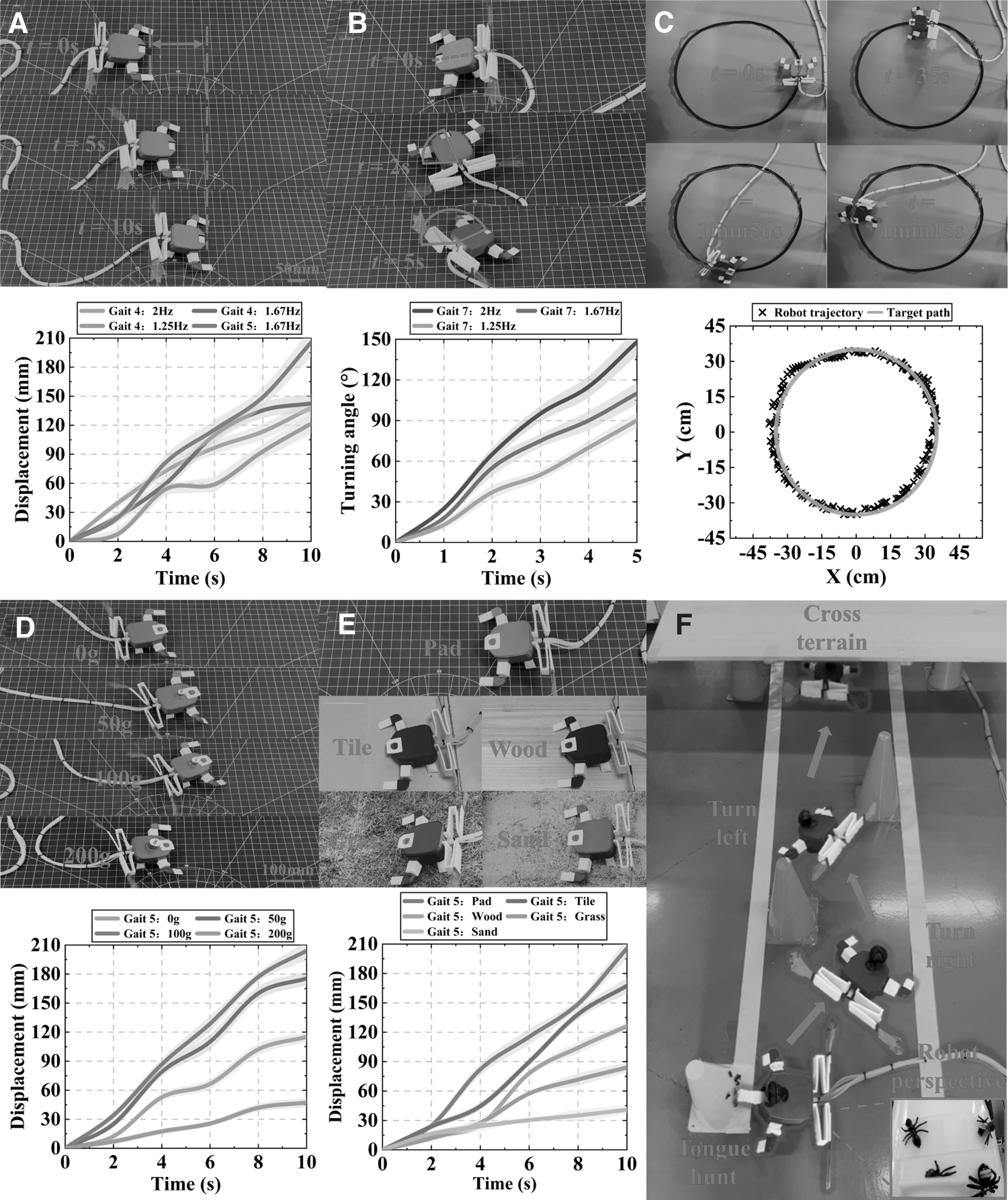
Robotic crawling and hunting proficiency assessment.
Crawling turning velocity test
The robot's crawling turning angle (Fig. 10B) was examined to investigate the impact on turning velocity at different frequencies f, with a fixed time of t = 5 s. The results revealed that higher frequencies enhanced the crawling velocity of the robot, enabling to achieve a velocity of 30° s−1 at a frequency of 2 Hz.
Evaluation of locomotion capabilities
In addition, to demonstrate precise control capabilities, remote operation was used to guide the robot along a path with a diameter of 70 cm, as depicted in Figure 10C. The carrying capacity of the robot was examined in Figure 10D, and a comparison was made between the crawling velocities of the robot, while carrying different weights at a frequency of f = 1.25 Hz, the experiment demonstrates that the robot's crawling velocity is the fastest when carrying a 100 g load, compared with other conditions within the specified 10-s time frame. The weight of a single TTOA is merely 7 g, yet it exhibits an impressive load-bearing capacity of 200 g, showcasing the remarkable structural robustness of the Kresling origami design. In Figure 10E, the robot traversed diverse terrains composed of different materials at a frequency f = 1.67 Hz, demonstrating its capability to navigate through complex environments.
Supplementary Movie S10 provides visual documentation of these experiments. Figure 10F illustrates the controlled execution of an insect-catching task by the robot, which successfully transported the captured insect to its intended destination. Further analysis and discussion on both crawling and hunting experiments can be found in Note S3 of Supplementary Data. Supplementary Movie S11 presents a detailed depiction of the robot's performance in capturing insects.
Locomotion energy efficiency analysis in crawling
The Equations (1), (2), and (3) can be utilized to compute the maximum locomotion energy of crawling robot, denoted as
Robotic amphibious proficiency assessment
Amphibious robots possess the ability to seamlessly transition between land and water, thereby demonstrating their remarkable amphibious switching capability (Fig. 11A, B). The key challenge lies in minimizing the time required for mode switching during amphibious motion. As the robot transitions from land to water, it smoothly switches from gait 5 to gait 1 when its head floats on the water surface. Conversely, when transitioning from water to land, once its head makes contact with solid ground and can no longer swim, it effortlessly shifts from gaits 1 to 5. Supplementary Movie S12 illustrates the experimental demonstration of amphibious transition by the robot. In addition, Figure 11C showcases a simulated experiment depicting the robot's successful transition in a complex outdoor terrain (Supplementary Movie S13). Further details are provided in Note S4 of Supplementary Data.

Composite images featuring sequential snapshots showcasing the amphibious locomotion capability of the soft robot are presented.
Discussion
Experimental validation demonstrates the viability and practicality of a bioinspired origami amphibious soft robot, which is based on the fabrication of origami actuators. The subsequent discussion encompasses the performance, characteristics, and functionality of this robotic system in terms of its structural composition, material properties, and operational capabilities.
Structural composition
The origami technology is a highly advantageous tool for transforming 2D structures into three dimensions, and the topological combinations of origami have demonstrated significant benefits such as large deformation, 53 high load-bearing capacity, 54 programmability, 55 and lightweight characteristics. 56 Four origami actuators are designed based on the Miura and Kresling origami prototypes: ZSOA, PFOA, and C/UOA. In addition, a novel concept that combines origami with bionics is proposed, in which these actuators mimic the postures of living creatures. This study confirms the substantial advantages of utilizing origami structures in a bioinspired design. Furthermore, it provides valuable insights and references for designing other bioinspired structures.
Material properties
The robot's origami actuator is constructed entirely from the flexible material TPE, while the remaining components are composed of polylactic acid. Using a 3D-printed modular design, this robot effectively mitigates manufacturing and assembling complexities. Given that most origami structures incorporate hollow cavities, they exhibit exceptional material efficiency. Remarkably, the combined weight of all origami actuators amounts to merely 90 g, which equates to <20 Renminbi.
Operational capabilities
The experiments have demonstrated that the robot designed not only had the ability to navigate forward and execute left and right on water, but also had the capability to move forward, right, as well as backward on land. Moreover, this robot had exceptional amphibious locomotion across different mediums: transitioning seamlessly from land to water and vice versa. In addition, it is capable of carrying heavy utilizing its tongue for insect hunting, avoiding obstacles effectively, and crawling across various terrains. To our knowledge, among the current bioinspired soft robots with amphibious capabilities, this the most comprehensive integration of both aquatic and terrestrial functionalities (Table 1 provides a comparative analysis of different bioinspired soft amphibious robots; “−” indicates unreported performance details in the article). The performance comparison with other robots can be found in Note S5 of Supplementary Data.
Comparison of Different Bionic Soft Amphibious Robots
BL/s, body length per second; SMA, shape memory alloy.
Conclusion and Future Work
This work presents the design and fabrication of a 3D-printed origami actuator for a bionic soft robot with amphibious locomotion and tongue hunting capabilities. The strengths of this work include the following: first, the development of four unique origami actuators based on the prototypes of Miura and Kresling origamis, including a ZSOA that mimics a frog swimming in water, TTOA, and PFOA, simulating the land crawl of a mudskipper, and an actuator (C/UOA) for the coiling/uncoiling movement of a hunting tongue. Second, a comparative parametric analysis of the motion posture of the origami actuator was performed to optimize robot performance. Third, a soft robot prototype was fabricated, and nine robot gaits were designed and tested through a series of experiments to demonstrate its powerful yet integrated amphibious capabilities and potential functions, such as hunting.
This work contributes to the development of advanced soft robotics with potential applications in environmental monitoring, search and rescue operations, and so on. In future research, the autonomous control of the robot's locomotion and amphibious transition will be investigated based on sensory feedback. An untethered robotic system design would also broaden the robot's application scenarios. Furthermore, sensors testing water quality such as pH value and turbidity would be integrated into the amphibious robot so that it could perform water quality monitoring tasks in the land–water transition zone.
Footnotes
Author Disclosure Statement
No interests to disclose.
Funding Information
This research was supported, in part, by the National Natural Science Foundation of China (Grant No. 52005269), the Research Project of State Key Laboratory of Mechanical System and Vibration MSV202319, and the GuangDong Basic and Applied Basic Research Foundation No. 2022A1515110067.

References
Supplementary Material
Please find the following supplemental material available below.
For Open Access articles published under a Creative Commons License, all supplemental material carries the same license as the article it is associated with.
For non-Open Access articles published, all supplemental material carries a non-exclusive license, and permission requests for re-use of supplemental material or any part of supplemental material shall be sent directly to the copyright owner as specified in the copyright notice associated with the article.
