




Abstract
Previous research on wearable robotics focused on developing actuation mechanisms while overlooking influences of skin movement. During finger flexion, skins on the opisthenar and finger back are stretched. Impeding such skin movement will obstruct normal finger motions. In this research, a statistical study on skin movement is proposed and conducted to quantify skin movement on human hands. Results of 30 subjects (15 men and 15 women) reveal that skin at the finger back extends by an average of 29.3 ± 7.2% in fist clenching. Based on this study, design guidelines for robotic gloves are proposed, and nominal strain values at different hand regions are tabulated for references in robotic glove design. To explore the influence of skin movement on wearable robotics, an elastomer-constrained flat tube actuator is proposed based on which two prototype robotic gloves are developed: one with an ergonomic strap interface that has small constraint to skin motion, and the other based on the commonly used fabric glove that is supposed to have large constraint to skin motion. With the same power input to the robotic gloves, the strap-based design achieves a finger motion range of 2.5 times and a gripping force of 4.3 times that of the conventional fabric glove.
Introduction
Human beings conduct various activities of daily life by controlling the movement of skeletal joints through muscles. However, some people may completely or partially lose the mobility of certain joints because of illness,1–3 accidents, 4 and aging. 5 Wearable robotic devices have been developed to assist patients with weak muscles to do specified exercises for rehabilitation.6–14 In the human body, hands play a pivotal role in human–environment interaction, and wearable robotic gloves have thus become a research hotspot in recent years.
Researchers are increasingly interested in the design of soft robots composed of soft materials and soft robotic gloves based on various actuators are reported in recent years.15–20 Compared with hand exoskeletons with bulky rigid linkage systems and cable-driven robotic gloves with frightening forced flexion motions,21–28 soft robotic gloves are safer, more compliant, and more comfortable. Besides, owing to the inherent compliance of soft actuators, dexterous, safe, and adaptive grasping can be achieved without sophisticated mechatronic systems. 29 Soft actuators used in soft robotic gloves are usually placed on the dorsum of fingers and controlled by air pressure to help flex fingers.30–35 Researchers have developed various interface methods to anchor actuators on hands, such as fabric glove, 36 soft polymer-based anchoring support, 37 Velcro straps, 24 and so on.
So far, researchers are preoccupied with soft actuator development but neglected the influence of interface methods, which may severely impair hand movement and even cause user discomfort. The human skin is a highly elastic material with an ability to safely stretch an average of 60–75%.38,39 When a joint rotates, the skin covering this joint elongates or contracts. When wearing a robotic device, if the side of the actuator in touch with the skin is too tight, it can hinder skin movement, thus restricting joint rotation. In summary, there are three research gaps in developing an ergonomic robotic glove: (1) the quantitative measurement of macroscopic elongation of local (around joints) and global skin (whole finger) on the finger back and opisthenar during full finger flexion; (2) tabulation of recommended nominal strain values at different hand regions; (3) interface methods with minimum user discomfort and impedance to skeletal joint motion; and (4) evaluation of interface methods on the performance of robotic gloves.
To design formfitting gloves, researchers tried to use 3D scanners to characterize skin deformation in hand regions. 40 These data are not suitable for robotic glove design as skin movements on finger joints and the whole finger are not measured. Besides, the reliability is severely restricted by the sway of measured hands, scanner resolution, and hidden hand regions. 41 In this article, we propose a reliable contactless vision-based skin motion measurement method that can measure all skin elongation on the hand providing useful data for designing ergonomic robotic gloves.
In the measurements, 30 healthy subjects were invited to test the skin elongation corresponding to the opisthenar and distal interphalangeal, proximal interphalangeal, and metacarpophalangeal joints (DIP, PIP, and MCP joints, respectively) of five fingers. Based on data from skin movement measurements, robotic glove design guidelines are proposed, and recommended nominal strain values at different hand regions are tabulated. To develop an ergonomic soft robotic glove, we present an elastomer-constrained flat tube actuator (EFTA) assisting finger flexion through pressure-controlled extension. Quasistatic modeling of the EFTA is developed to estimate EFTA's performance, and experimental tests are conducted to characterize the performance of the EFTA.
Based on the EFTA, we developed two soft robotic glove prototypes to evaluate the impact of the human–robot interface. One is based on a typical fabric glove, and the other is a strap structure designed with references to the proposed robotic glove design guidelines. Ten subjects were invited to experiment with gloves for range of motion (ROM) and grip strength measurements. On average, the strap structure design achieves 2.5 times of ROM, and 4.3 times of grip strength compared with the fabric glove design. The comparison of subjective experience in wearing the two gloves is measured by a 5-point Likert scale questionnaire. The result shows that most subjects consider the strap structure more comfortable than the typical fabric glove.
Skin Motion on the Dorsal Hand
Mechanism of skin motion
The skin covering finger joints is abundant in wrinkles that will flatten when fingers bend. Owing to the elasticity and the rough microstructure (Fig. 1) of the epidermal skin, the skin on the opisthenar is also stretched during finger flexion. In finger motion, the PIP and DIP joints are coupled, 42 and the MCP joint is independent. If you pin the skin of the opisthenar near the middle finger MCP joint and try to bend all MCP joints, you will feel an obvious obstruction in bending. But if you try to bend only the PIP joints at the same condition, the motion of these joints has no obstruction. This implies that the skin motion of the opisthenar is dependent on the motion of the MCP joint. To quantify the macroscale elongation of the skin, the dorsal skin motion of each finger is simplified into a line motion along the extensor. The corresponding skin from the wrist to the fingertip along each finger is separated into four regions: the opisthenar, the MCP joint, the PIP joint, and the DIP joint as given in Figure 1.

Schematic of skin motion on the hand and the division of four regions: the opisthenar, the MCP joint, the IP/PIP joint, and the DIP joint. DIP, distal interphalangeal; IP, interphalangeal; MCP, metacarpophalangeal; PIP, proximal interphalangeal.
Skin elongation
Wrinkles on the dorsal finger are mainly concentrated around the PIP joint in each finger. In addition, flattish wrinkles exist on the skin over the MCP joints, and the skin of this region shows high elasticity. The skin over the DIP joint is relatively tight and smooth. Meanwhile, the skin elongation of each region is also positively related to the ROM of each joint, and the ROM of the PIP joint is larger than other joints. 43
In this study, we measured the maximum skin elongation. Locations of markers and labels for region division and skin movement measurement are given in Figure 2. Fifteen labels are pasted on the opisthenar (Fig. 2A) to define the skin elongation of the opisthenar along the direction of each finger. For example, on the opisthenar corresponding to the index finger direction (Fig. 2), the skin elongation is:
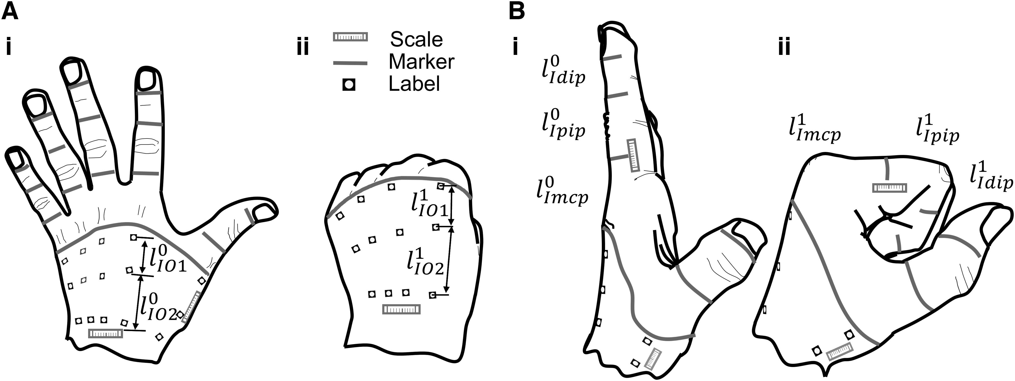
Characterization of the skin motion on finger back and the opisthenar.
where
To evaluate the skin motion at the MCP joint region, the elongation is:
The skin elongations of all regions are evaluated in the same way. For the thumb, only the IP and MCP joints are considered in evaluating the skin elongation of the whole thumb. The skin on the dorsal hand is divided into 19 local regions, and 5 global regions (Supplementary Fig. S1).
Skin motion test
Participants
Thirty healthy subjects were recruited to participate in the skin motion measurement tests. Before testing, record the subjects' information as Supplementary Table S1, and all tests used the dominant hand without any wound or disease history. The experimental procedures were approved by the Human Research Ethics Committee of the University of Hong Kong with number EA1903040. We have the informed written consent of the participant.
Protocol
Before testing, the investigator puts labels and scales on the subject's hands and uses a marker pen to divide joints as given in Figure 3A. The labels are distributed along the direction of extensors at finger full extension state. The markers are to measure the skin length of neighbor joints, which are printed on the middle section of each phalange.

Skin motion test setup and protocol.
During the skin motion test, subjects were asked to try their best to bend their fingers while their hand motions were recorded by a camera (Fig. 3B). Scales put on the hand are metrics to calibrate the imaging system to physical units (mm). Subjects were asked to do specific hand gestures (Fig. 3C–I). First, the skin motion on the opisthenar for four fingers was imaged as given in Figure 3C. The surface of the opisthenar relating to the thumb was recorded individually in Figure 3D. With the palm facing upwards, the skin movement on the thumb back was captured as given in Figure 3E. For some fingers, the front finger was adjusted to avoid blocking markers and scale on the tested finger (Fig. 3F–H). The measurement of the ring and little fingers (Fig. 3H, I) were conducted by overturning the hand. For subjects with fingers not flexible, the investigator could help them to adjust hand gestures without influencing skin motions in the tested area (Fig. 3H[II]).
Data analysis
The distances between adjacent markers/labels were measured using the software ImageJ as given in Supplementary Figure S2, and skin elongations were calculated based on equations (1)–(3). Statistical analyses were performed using Statistical Package for the Social Sciences, version 27 (IBM). First, a Shapiro–Wilk test was performed to estimate the normality of data distribution of the 24 hand regions grouped by gender. If the p-value of the Shapiro–Wilk test is >0.05, the null hypothesis (H0—the data is not normally distributed) is not rejected, and the independent samples t-test was used to compare differences in skin elongations of all hand regions caused by gender. All tests were two-sided, and statistical significance was determined using p-values, with a value of <0.05 considered statistically significant.
Results
The skin elongation results grouped by gender are presented in Figure 4. For the whole finger skin motion the skin elongation of the five fingers is plotted in Figure 4A. The skin elongations (Fig. 4B) on the opisthenar are significantly smaller than the other regions. Similarly, elongations of the skin covering joint regions are presented in Figure 4C–E. The little finger has a significantly higher average elongation at all joints compared with other fingers. Of note, the skin covering the IP/PIP joint is stretched by an average of 45.0% during finger flexion.

Skin elongation of finger back and the opisthenar during full finger flexion.
The skin elongations relating to all regions do not show evidence of non-normality, which is proven by the Shapiro–Wilk test (p > 0.05) (Supplementary Table S2). Based on this outcome, independent samples t-test is chosen to compare the skin elongation difference of 24 regions caused by gender (Supplementary Table S3). The results showed that there is no significant difference in skin elongations of all regions between male and female groups.
Based on the skin movement measurement results, the following guidelines about robotic glove designs are proposed: (1) there should be holes or stretchable fabric around joints in soft robotic gloves. (2) If stretchable fabric is used, nominal strain values of such fabric at different regions of hand are suggested in Table 1 (average value of skin strain from all subjects). (3) Strains on the opisthenar region are measured along each finger, and recommended strain values are also provided in Table 1. (4) There should be inelastic fabric on the glove corresponding to the phalange and opisthenar regions to anchor actuators stably on hand.
Recommended Nominal Strain Values at Different Glove Regions
DIP, distal interphalangeal; IP, interphalangeal; MCP, metacarpophalangeal; N/A, not applicable; PIP, proximal interphalangeal.
Elastomer-Constrained Flat Tube Actuator
Based on the design guidelines mentioned previously, an EFTA is proposed. This actuator design has different strain values when different elastomer material hardness is used. Thus, it is possible to fabricate actuators whose strain values conform to those tabulated in Table 1.
Design of the EFTA
In the EFTA, the flat tube is folded and embedded into a silicone rubber matrix (Fig. 5A). When inflating, the folds inside the silicone rubber will bulge, enabling the extension of the EFTA (Supplementary Movie S1). When deflating, the EFTA will return to its original position owing to the elasticity of silicone rubber. The EFTA is used to drive finger joint rotation as given in Supplementary Figure S3.

Design and characterization of the EFTA.
Materials and fabrication of the EFTA
The flat tube used in this article is a polyethylene heat shrink tube with an inner diameter of 8.5 mm and a wall thickness of 0.15 mm. The elastomer is silicone rubber (Ecoflex-0030; Smooth-on, Inc.). The fabrication process of the EFTA is given in Supplementary Figure S4.
Characterization of the EFTA
In this research, we have developed a quasistatic model of the EFTA based on the three-dimensional constitutive model of rubber materials.44,45 The quasistatic model is inferred in Supplementary Appendix SA1 and Supplementary Figure S5.
Strain test
During the test, one end of the EFTA was fixed, and another end was connected to a linear guide rail. The experimental platforms used for the strain, dynamic response, and cyclic load tests are the same as given in Figure 5B. For the strain test, the air pressure increased from 0 to 120 kPa. For every 10 kPa increment, we measured the length of the EFTA. The strain test was conducted five times, and the average values together with error bars are plotted in Figure 5C. The EFTA extends with a strain of 62.5% at 120 kPa pressure input.
Actuation force test
For the force test, the air pressure input is increased from 0 up to 150 kPa. For each 10 kPa increment, the actuator force was recorded as in Figure 5D. The test was conducted five times, and the mean values with error bars are presented in Figure 5E. When air pressure reaches 150 kPa, the actuator force FEFTA is up to 27.08 N.
Dynamic response test
The pressure input is 90 kPa provided by the air tank, and exchange frequencies of the inflating and deflating are controlled using a solenoid valve. The extension of the EFTA was recorded by a laser distance sensor with a sampling frequency of 100 Hz. Actuating the EFTA from its initial state (0 kPa) to the fully extended state 90 kPa takes 1.06 s (Fig. 5F), and the recovery time is 1.6 s. During inflating, the actuator extends rapidly at the beginning and then slows down to a balanced state because of the increasing resistance force of the silicone rubber. During recovery, the actuator contracts dramatically at first and then slows down, which is caused by the diminishing release of air pressure and the attenuation of the elastic force of the silicone rubber structure. The EFTA motion cycles with exchange frequencies of inflation and deflation spanning from 0.25 to 2 Hz were tested to evaluate the dynamical behavior (Supplementary Fig. S6).
Cyclic load test
The inflating/deflating exchange frequency for the cycle test is 0.5 Hz, and the cycle was conducted almost 5000 times with 95 kPa pressure input. The strain of the FFTA slightly increases with the increase of the cycle time (Fig. 5G). This might be caused by the degradation of the silicone rubber walls. The curves of the EFTA at the first and last three cycle times in the cycle test are singled out and given in Figure 5G(I) and (III) respectively. The EFTA strain in the first three cycles is in the range of 2.2–45.1%, and the strain range changes to 9.7–62.2% in the last three cycles.
Soft Robotic Gloves Based on the EFTA
Design
The skin on the dorsal side of the fingers elongates during finger flexion, whereas the palm-side skin is compressed simultaneously (Fig. 6A). Based on the design guidelines of robotic gloves proposed in the previous section, an ergonomic strap interface structure imposing few restrictions on skin motion is proposed in Figure 6B. The strap consists of a low elastic fabric layer providing pliable and comfortable support on the palm side of fingers, and a double-sided Velcro tape for quick wear.

Design of soft robotic gloves.
To investigate the influence of the human–robot interface, two robotic gloves based on the EFTA are built and evaluated. One is based on the strap interface, named the glove version a in Figure 6C(I). The other one is based on the commonly used fabric glove interface (glove version b in Fig. 6C(II)). The actuators used in glove version a are the same as version b for each finger. In glove version a, the bottom of the EFTA is stretchable with strain values roughly in line with the proposed design guidelines. The actual strain values of each EFTA in glove version a at 90 kPa are given in Table 2. Meanwhile, in glove version b, EFTAs are attached to inextensible Velcro tapes. For the index, middle, and ring fingers, the design parameters of actuators for the three fingers are the same (Supplementary Table S5).
Actuator Strain Values of the Version-a Robotic Glove at Different Glove Regions
For the little finger, the length of each EFTA unit is smaller than that of the index finger by 4 mm, and the EFTA for each joint has one less fold to accommodate the size of the little finger. For the thumb, the EFTA parameters are the same as those of the index finger without the DIP joint. Four sizes (small, medium, large, and extra-large) of fabric gloves are designed to provide a base for modular quick disassembly and assembly achieved by Velcro tapes. The inflating and deflating of both robotic gloves are controlled by a control box with a weight of 650 g (Supplementary Fig. S7).
When input air pressure is 90 kPa and the user keeps the hand in a relaxed state, glove version a can completely clench the user's hand, but glove version b only bends the finger almost 80° (Supplementary Movie S1). A further comparison between proposed robotic gloves and classic soft robotic gloves from previous research is also given in Supplementary Table S4.46,47 The proposed EFTA-driven glove version a can provide a comparable motion range and gripping force at a much smaller input air pressure.
Performance Comparison of Soft Robotic Gloves
Ten subjects were invited to do the ROM test and grip force test using two robotic gloves. After experimenting with the two robotic gloves, they were asked to fill out a questionnaire. The questionnaire evaluates subjective assessment on five points: motion assistance, strength assistance, comfort level, motion obstruction, and safety level, which are marked as Q1–Q5, respectively. The higher score the robotic glove gets, the better assessment the subjects give. To avoid errors caused by the sequence of robotic glove use, half of the participants did glove performance tests using the glove version a first, and the other half were tested in the reverse sequence.
Grip force test
During the grip force test, participants were required to relax their dominant hands and put their hands flat on the table wearing robotic gloves (Fig. 7A, B). Then, the subjects kept relaxing, and the investigator activated robotic gloves to continuously grip the hand dynamometer (Vernier) three times (Fig. 7C). Grip forces using the two gloves were tested. As given in Figure 7D, the average grip force of overall subjects for glove version b is only 1.8 ± 0.4 N. Meanwhile, the average grip force of glove version a is up to 7.74 N, which is 4.3 times the gripping force of glove version b.

Grip force test.
ROM test
To evaluate the ROM assisted by robotic gloves, a ROM meter is designed in this research (Fig. 8A). Compared with other ROM estimation methods (like using goniometer, 48 electromagnetic tracking system, 11 and image processing 17 ), the ROM meter is more convenient, available, and intuitionistic, without fussy marker/sensor preprocess and complex image/signal postprocessing. Before activating robotic gloves, subjects placed the dominant hands flat on the table and extended their fingers, and then adjusted the ROM meter to the proper position and zeroized it (Fig. 8B(I)). Then subjects were asked to relax their hand, and robotic gloves were activated to squeeze the ROM meter. The test results of the ROM can be read directly through the electronic screen (Fig. 8B(II)). Each glove was tested three times to alleviate errors.

ROM test.
The ROM of each subject and the average value of all subjects using two gloves are illustrated in Figure 8C. Although the ROM meter has resistance owing to the return spring and the friction of the linear guide rod, some subjects (e.g., M15) were able to reach the maximum range with the help of glove version a. The average ROMs of overall participants for glove versions a and b are 57.86 ± 11.44 mm and 23.64 ± 6.69 mm, respectively. Compared with the conventional fabric glove interface, the strap interface increases the ROM by almost 2.5 times.
Subjective evaluation and comparison of soft robotic gloves
After the ROM test and grip force test, participants wearing gloves moved their hands to feel the obstruction of the gloves. Finally, they were asked to fill out a questionnaire (Supplementary Table S6). Figure 9 provides the questionnaire results about the average scores of each question and the overall average scores of the five questions. In each of the questions, the scores of glove version a are distinctly larger than glove version b. The overall average scores for glove versions a and b are 4.34 ± 0.84 and 3.08 ± 1.13, respectively. Of note, for Q3 and Q4, glove version a scores average 3.8 and 4.2 points, respectively, which are far larger than glove version b (2.8 and 2.5 points). This shows that the ergonomic strap interface is more comfortable and dexterous compared with the conventional fabric glove interface.

Subjective comparison of user experience using the two robotic gloves. Q1–5 refers to questions about motion assistance, hand strength assistance, comfort level, degree of obstruction, and safety level, respectively.
During the characterization of the soft robotic gloves, most participants feel the robotic glove version a is more comfortable than glove version b. However, for a special case, young female no. 14 (YFM 14), she feels the robotic glove version b is more comfortable than version a. The reason is that the strap size and the distance between EFTAs are not adjustable. So, for this case, the size of glove version a is not suitable for her hand size. Even with the mismatch of glove size, in the ROM tests and gripping force tests, glove version a still shows better performance compared with glove version b.
Discussion and Conclusion
Skin motion is a commonly neglected factor in wearable robot design, and there is no quantitative study on skin elongation and its effect on robotic performance in previous research. In this study, we proposed a measurement strategy for skin movement using vision, and 30 subjects were invited to conduct this test. Based on the data acquired from the skin motion test, we proposed design guidelines for robotic gloves, and suggested nominal strain values for different glove regions.
To design a soft robotic glove with few restrictions to skin deformation during hand motions, an EFTA was developed. Based on the EFTA and design guidelines, we fabricated a robotic glove version a with an ergonomic strap interface that does not hinder skin motion at all, and a robotic glove version b with a traditional fabric glove that is almost inextensible along finger directions to study the influence of hindering skin motions on robotic glove performance. The soft robotic glove version a presents significantly better mechanical performance and comfort level than the conventional fabric glove interface. The main users of soft robotic gloves are the elderly people who have impotent hand functions, and their hands are more fragile and sensitive than young people. The robotic glove version a abided by the proposed design guideline solved the pain point of the inflexible human–robot interface, and reduced discomfort to the user.
This is still an early study. Some limitations and further developments are summarized as follows: (1) optimized selection of elastomer material and its optimum structural design. This allows better actuator durability and conformance of strain values to the recommended values. (2) In this study, we only tested two extreme designs: one with free skin motion (version a) and the other is constrained skin motion by inextensible fabric (version b), there might be other possibilities for robotic glove design. (3) Strain values of actuators do not fully conform to the recommended values because only a single elastomer material was used to make prototype actuators. To better follow the recommended strain values, different elastomer materials should be used to fabricate actuators for different finger joints. (4) The methodology of hand skin motion and its effect studies can be further extended to knee joint, elbow, wrist, ankle, and shoulder robots where large skin movements are observed. (5) The subjects invited for skin motion tests are all Chinese. There may be differences in skin elongation for people from other races.
Footnotes
Authors' Contributions
Y.C. and H.L. conceived the ideas and designed the research. H.L. conducted the experimental works and analyzed data. H.L. designed and fabricated the experimental platform and robotic glove prototypes. H.L., C.W., and S.L. contributed to modeling and performed the MATLAB simulation. H.L. and Y.C. wrote the article. Y.C., N.X., V.W.Q.L., Y.H., and C.K.L.O. commented on measurements. All authors discussed the results and contributed to the final version of the article.
Author Disclosure Statement
No competing financial interests exist.
Funding Information
The work described in this article was fully supported by a grant from the Research Grants Council of the Hong Kong Special Administrative Region, China (Project no. [T42–717/20-R]).

References
Supplementary Material
Please find the following supplemental material available below.
For Open Access articles published under a Creative Commons License, all supplemental material carries the same license as the article it is associated with.
For non-Open Access articles published, all supplemental material carries a non-exclusive license, and permission requests for re-use of supplemental material or any part of supplemental material shall be sent directly to the copyright owner as specified in the copyright notice associated with the article.
