




Abstract
Various fields, including medical and human interaction robots, gain advantages from the development of bioinspired soft actuators. Many recently developed grippers are pneumatics that require external pressure supply systems, thereby limiting the autonomy of these robots. This necessitates the development of scalable and efficient on-board pressure generation systems. While conventional air compression systems are hard to miniaturize, thermopneumatic systems that joule heat a transducer material to generate pressure present a promising alternative. However, the transducer materials of previously reported thermopneumatic systems demonstrate high heat capacities and limited surface area resulting in long response times and low operation frequencies. This study presents a thermopneumatic pressure generator using aerographene, a highly porous (>99.99%) network of interconnected graphene microtubes, as lightweight and low heat capacity transducer material. An aerographene pressurizer module (AGPM) can pressurize a reservoir of 4.2 cm3 to ∼14 kPa in 50 ms. Periodic operation of the AGPM for 10 s at 0.66 Hz can further increase the pressure in the reservoir to ∼36 kPa. It is demonstrated that multiple AGPMs can be operated parallelly or in series for improved performance. For example, three parallelly operated AGPMs can generate pressure pulses of ∼21.5 kPa. Connecting AGPMs in series increase the maximum pressure achievable by the system. It is shown that three AGPMs working in series can pressurize the reservoir to ∼200 kPa in about 2.5 min. The AGPM’s minimalistic design can be easily adapted to circuit boards, making the concept a promising fit for the on-board pressure supply of soft robots.

Introduction
Numerous fields stand to gain significant advantages from the development of effective actuation mechanisms employing soft materials, including medical robotics, artificial muscles, and other devices designed for human interaction. 1 Researchers are currently exploring various potential options for creating soft actuators. Much of this research is centered around soft materials capable of converting electrical energy into mechanical energy. Possible candidates are electrostrictive, dielectric or piezoelectric polymers.2–5 However, the practicality of actuators employing said polymers is constrained by their reliance on either significant electric fields or flexible electrodes. 6 Alternative approaches utilize photo- or thermoresponsive polymers that release mechanical energy when triggered by external stimuli. 7 Recent studies have presented bioinspired pneumatic grippers and actuators that can be operated by pressurized air. These devices are fabricated from structured soft materials and provide significant actuation strength when inflated with 0.5 kPa of pressure.5,8–10 As the pressurized air can be supplied from a centralized source, the actuators themselves are not limited by electrodes or accessibility to external stimuli. The bioinspired grippers can be supplied by including a gas tank in the robot design, the tank would require regular refilling, reducing the autonomy of the robot. On top, conventional air compression systems have many moving parts and still proof challenging to miniaturize, limiting the size of the robot. 11 For the full realization of autonomous mobile robots using pneumatic actuators, it is therefore necessary to develop on-board pressure generation systems.
In thermopneumatic pressure generators, a Joule-heated transducer material transfers heat to a working gas. If the volume of the working gas is confined, the resulting increase in temperature causes an increase in pressure. The relationship between pressure, volume, and temperature of a gas can be sufficiently described using the ideal gas law
12
:
The achievable pressure and response time of a thermopneumatic system are determined by the maximum temperature of the transducer material as well as its surface area in contact with the working gas. Previously presented thermopneumatic systems use pleated or coiled metal wires to heat the working gas.13,14 The limited surface area of the wire restricts a rapid heat transfer to the working gas. Therefore, conventional thermopneumatic systems have long response times. The high heat capacity of the wire also leads to high cooling times between Joule-heating cycles, limiting the operating frequency. 13
This study presents a new kind of thermopneumatic pressure generator using aerographene as its transducer material. Aerographene is a hierarchical network of freestanding graphene microtubes with a porosity of >99.99%.15,16 Aerographene is characterized by a low volumetric heat capacity comparable to that of air, a high electric conductivity (∼50 S m−1) and a high thermal stability.16,17 Furthermore, the open porous and hierarchical internal structure of the aerographene offers a large and universally accessible internal surface area which enables efficient heat transfer to the gas in and around the aerographene network structure. Previous works have demonstrated rapid Joule heating of aerographene with heating rates exceeding 300000 K s−1, which can be used to drive pumps as well as actuators. 16 Aerographene is therefore a promising candidate for the transducer material of thermopneumatic pressure generation. The here presented aerographene pressurizer module (AGPM) can generate high maximum pressures at low response times and high repetition rates. Multiple AGPM can be combined for enhanced pressure generation, providing an additional dimension of scalability. With its minimalistic design featuring only two check valves as moving parts, the AGPM can be easily adapted as the board pressure generator for soft robots.
Results and Discussion
The AGPM is fabricated as illustrated by Figure 1. The transducer material of the AGPM is an interconnected network of hollow graphene microtubes called aerographene. The aerographene is prepared as described elsewhere.15,16 A more detailed description is presented in the supplemental information under Supplementary Data S1. Tetrapodal zinc oxide (ZnO) microparticles are molded into templates (20 × 20 mm with a thickness of 3–5 mm) and sintered (5 h at 1150°C).

Fabrication of aerographene pressurizer module
The process creates highly porous (∼94%) networks of interconnected tetrap7ds. The templates are highly hydrophilic and can be infiltrated with an aqueous dispersion of 1.4 mg ml−1 electrochemically exfoliated graphene (EG). 19 Upon drying, the graphene deposits on the tetrapod arms. Repeating the infiltration seven times results in a homogenous self-assembled thin film of graphene on the ZnO network. The samples are then wet-chemically etched to remove the underlying t-ZnO and then critical point dried. The resulting aerographene is a freestanding network of interconnected graphene microtubes with an ultralow density of ∼10 mg cm−3 and an exceptionally high porosity (>99.99%). Using the template approach, the geometry and the network density of the aerographene can be adapted to their use-case. Aerographene samples in various forms and sizes ranging down to 3 × 3 × 3 mm are easily possible. Figure 1a shows a photograph of a finished 20 × 20 × 4 mm aerographene sample with a cross-sectional scanning electron microscopy of the internal structure and schematics of the aerographene microstructure as additions. The hollow graphene microtubes are roughly 50 µm in length and 3 µm across with a wall thickness of about 25 nm. 15 The aerographene is then electrically contacted using conductive silver paste and brass rods and mounted into the pressurizer module. The module is sealed using a sheet of silicone rubber and a top lid. A schematic of the assembly with the individual parts and a photograph of an assembled AGPM are presented in Figure 1b and Figure 1c, respectively. With only two moving parts (the check valves) that can be easily replaced, the AGPM is simple and cheap to maintain with minimum downtime. While the current design still features a rather thick casing and bulky contacts, leading to an overall size of 45 × 45 × 20 mm, further development should enable the adaptation of the AGPM as a surface mountable device for circuit boards. The minimalistic design can be easily miniaturized and adapted to fit on-board electronics of small robots. The necessary electric power could be provided by an inductively chargeable battery. The AGPM would therefore be suitable as pressure supply in highly autonomous soft robots.
Aerographene exhibits a low volumetric heat capacity (1–5 kJ m−3 K−1) and a high electric conductivity (∼50 S m−1). 16 In combination with the high thermal stability of graphene, these properties enable rapid Joule heating at low-power consumption. Under an oxidizing atmosphere, aerographene is stable up to temperatures of ∼400°C. Under inert gas, even higher temperatures of up to 800°C are possible without considerable degradation. 20 Figure 2 presents the results of a thermographic analysis of the Joule-heating behavior of the aerographene used in the AGPM. All further reported values for electrical powers are averaged over the duration of the power pulse. Figure 2a shows a photograph of the sample as well as infrared images of 20 × 20 × 5 mm aerographene taken 30, 90, and 180 ms after the start of a heat pulse of 54 W for 100 ms. The material heats up rapidly and homogenously with only the boundary regions in contact to the brass rods being significantly colder than 300°C. This is due to heat conduction to the contacts. The complete infrared video in slow motion is supplied in Supplementary Video SV1. The histogram presented in Figure 2b was calculated from the temperature data of the IR image taken after 90 ms. The mean temperature of the sample was ∼306 ± 59°C, with ∼70% of the material showing temperatures above ∼280°C. A table with the temperature distribution data is provided in the supplemental information (Supplementary Table S1). Figure 2c shows the maximum temperature of the 20 × 20 × 5 mm sample over time when power pulses of equal energy, but different pulse lengths are applied. The maximum temperature decreases with pulse length. While the AGPM reached a temperature of 438.67 ± 8.39°C when ∼5.2J were applied over 50 ms, it only reached 353.67 ± 9.61°C when the same energy was applied over 200 ms. The effect is more pronounced for modules employing aerographene of higher thickness. In Figure 2d, the temperature response of aerographene to power pulses adjusted to heat the material to 400°C is shown. From fitting the cooling curves, it can be estimated that the aerographene cools down to 30°C in less than 5 s (Supplementary Fig. S3).

Joule heating of 20 × 20 × 5 mm aerographene sample.
The energy required to heat the aerographene increases with pulse length. In contrary to the effect on the maximum temperature, the effect of the thickness on the energy required to heat the active material to 400°C is smaller for thicker aerographene samples. While the aerographene requires a rather high peak power of up to 110.64 ± 18.84 W to reach 400°C (50 ms pulse for 20 × 20 × 5 mm of aerographene), this power is only needed for a fraction of a second. Overall, only 3 to 5.5J of energy are required per heating pulse depending on the thickness of the sample and the length of the power pulse. A more detailed analysis of the power consumption and maximum temperature for varying pulse lengths is presented in the supplemental information (Supplementary Data S2). The long-term cyclability of a 20 × 20 × 5 mm aerographene sample is demonstrated in Figure 2e. The sample was repeatedly heated to ∼400°C by applying 50 W for 100 ms a total of 50 times. Between each pulse, the system was left to cool for 1400 ms. No significant changes in the temperature response of the aerographene were observed, indicating that no thermal degradation of the aerographene or the contact areas occurred.
The open porous aerographene network has a high and fully accessible volumetric surface area (∼0.14 m2 cm−3). When the aerographene in the AGPM is Joule heated, heat can be efficiently transferred to the air in and around the material. As the aerographene has a very small Knudsen number (≪1), the properties of the gaseous phase can be estimated to that of free gas.
16
The heated air can therefore move out of the material freely. These properties enable electrically powered repeatable air explosions as demonstrated in previous works.
16
By outfitting the AGPM with check valves on the in- and outlet, a unidirectional gas flow can be created. The AGPM can therefore be used as a pump.
16
As demonstrated in Supplementary Video SV2 AGPM employing 3 mm and 4 mm thick aerographene can continuously pump air against a constant external pressure of ∼1 kPa. The AGPM was operated at a frequency of 0.66 Hz using 100 ms power pulses of 34 W (3 mm) and 45 W (4 mm), respectively. Using the recording, a mean air flow rate of 33.5 mL min−1 can be estimated for the 4 mm AGPM. Being 27.5 mL min−1, the mean air flow rate is slightly lower for the 3 mm AGPM. A more detailed overview on the AGPM’s pumping performance is provided in the supplemental information (Supplementary Data S3). When the AGPM is connected to a sealed container at the outlet, the system can be used for pressure generation. A detailed characterization of the pressure generation by a single AGPM is shown in Figure 3. The AGPM was outfitted with medical grade fluidic check valves and connected to a pressure reservoir with a volume of ∼4.2 cm3. A photograph of the setup used for the pressure generation is shown in Figure 3a. Joule heating the aerographene transfers heat to the air in and around the material. Following the ideal gas law (Equation 1), the pressure in the AGPM increases proportional to the change in temperature. Due to the excess pressure in the module, the outlet check valve opens. The pressure in the module and the pressure reservoir equalizes by pushing air from the module into the reservoir. Once an equilibrium is achieved, the outlet check-valve of the module closes. After the heat pulse the pressure in the system decreases as the air cools down. Due to the increased amount of air in the reservoir, its pressure stays above the initial value. The pressure in the AGPM on the other hand falls below ambient pressure. Thereby, the inlet check valve of the module opens, and cool air can flow in to reset the AGPM. The pressure generated by the AGPM is determined by the temperature increase of the air in and around the graphene caused by the Joule heating. Repeating the procedure periodically causes a stepwise increase in pressure of the reservoir. Figure 3b presents the pressure evolution for periodically operated AGPM employing 20 × 20 mm of aerographene with varying thickness. The transducer material is operated with power pulses that, based on the results of the Joule-heating characterization (Fig. 2 and Supplementary Data S2), will heat the aerographene to ∼400°C. The generated pressure varies for AGPM employing aerographene of different thicknesses. On the initial pulse, the 3 mm AGPM created 10.6 ± 0.2 kPa. The 4 mm and 5 mm AGPM generated significantly higher initial pressure of 13.8 ± 1.1 kPa and 13.2 ± 0.2 kPa, respectively. The pressure difference is smaller for each consecutive pulse until a maximum pressure is reached. After 10 pulses all modules reached their maximum pressure. The 3, 4, and 5 mm AGPM generated maximum pressures of 27.2 ± 1.5, 34.1 ± 3.0, and 31.6 ± 1.0 kPa, respectively. As there is a necessary gap between the aerographene and the housing (1 mm), the filling factor (

Pressure generation by single AGPM
Power Used for Pulses of Varying Length to Joule-Heat Pressurizer Modules with 20 × 20 Mm AGPM of Different Thickness
AGPM, aerographene pressurizer module.
Figure 3c presents the pressure evolution for 4 mm AGPM modules that were operated with pulses of different lengths. The power of each pulse was set to heat the module to ∼400°C (see Supplementary Data S2). As already mentioned in the discussion of the Joule-heating behavior above, energy required to heat the aerographene to ∼400°C increases with the length of the power pulse. While a pulse of 50 ms needs to be performed using 80 W, a pulse of 200 ms requires 25 W of power. However, even though the longer pulse applies more energy, the maximum pressure reached is lower. The added energy is therefore not used to heat the air in the system but is likely lost through heat conduction to the electrical contacts and the housing of the module. In can be concluded that the ratio between heat transferred to the air and heat transferred to the contacts decreases with pulse length. Shorter pulses are therefore favorable for pressure generation. As the pressure generated by the AGPM depends on temperature difference generated through the Joule heating, the system needs to cool down in between pulses to reach maximum overpressure. Figure 3d shows the resulting pressure curves of 4 mm APGM pulsed 10 times with pulses of equal energy but different cooling intervals in between each pulse. When operated with 20 pulses per minute, the tested AGPM reached a maximum pressure of ∼36.5 kPa in 30 s. At 30 and 40 pulses per minute, maximum pressures of ∼35 kPa in 15 s and ∼34.5 kPa in 10 s were achieved, respectively. The shorter the cooling interval, the higher the residual temperature of the aerographene at the start of the next pulse. Although higher starting temperature will result in a maximum temperature, the difference between starting and maximum temperature will be smaller. The maximum pressure reached by the AGPM therefore decreases with the cooling interval. However, the difference in maximum pressure smaller than one would expect from looking at the cooling behavior of the aerographene after heating (Fig. 2c, d). This is most likely due to increased cooling from cool air flowing in after the pulse. The repetition rate is also the determining factor for the long-term power consumption of the AGPM. As mentioned above, the energy required for individual power pulses ranges from 3 to 5.5 J depending on the thickness of the used aerographene and the length of the pulse. The configuration reaching the highest maximum pressure, 4 mm thick aerographene and 100 ms pulses, requires ∼4.5 J of energy per pulse. At a repetition rate of 20 pulses per minute, i.e., 0.66 Hz, the mean power consumption of the device would surmount to 3 W. At 40 pulses per minute, the power requirement doubles to 6 W. Lower repetition rate is therefore favorable for the overall power consumption of the system. Not just the module, but also the gas in the pressure reservoir needs time to normalize its temperature (see Supplementary Data S4). The maximum reachable pressure at higher repetition rate could be further increased by enhancing the system’s ability to cool. This could be achieved by, for example, using anodized aluminum for the casing of the AGPM. The high thermal conductivity of aluminum could improve the cooling rate of the module while the anodization would prevent short circuiting the aerographene. The aluminum would also provide the electromagnetic shielding necessary for on-board electronics in robotic systems. As demonstrated by Figure 3e, the pressure generation capability of the AGPM can be further improved by increasing the network density and thus the internal surface area of the active aerographene material. The pressure curves of AGPM fabricated with aerographene produced from templates with twice the t-ZnO density (0.6 g cm−3) are compared with a reference produced with 0.3 g cm−3. The modules with higher template density generated 37.3 ± 2.8 kPa, which is a 10% higher maximum pressure than the reference. The modules reached the maximum pressure in the same number of pulses, indicating that the increased network density did not impact the volume of air heated. These results indicate that the aerographene itself offers additional potential for further optimization of the AGPM. Even without optimization the AGPM is already capable of supplying the necessary air flow and pressure for the operation of soft pneumatic actuators. A demonstration is provided in Supplementary Video SV3 showing an AGPM directly driving a self-designed silicone soft actuator. A single pulse of the AGPM already results in significant deflection of the micro-bellow actuator with two pulses being enough to fully inflate it. The demonstration also showcases the short response time of AGPM. As the pressure generated by the individual pulse can be tailored via the applied power and pulse length, the AGPM would therefore be able to provide precise and rapid soft actuation.
The scalability of the AGPM concept is demonstrated in Figure 4a by connecting several modules together. APGM can be connected and operated parallelly or in series to achieve improved pressure results. By connecting multiple modules in series and pulsing them alternatingly (45 W for 100 ms at 40 ppm), the maximum pressure reached by the system is significantly increased. Figure 4b shows the pressure curves for 2 and 3 modules in series compared with a single module. In the 15 s, a single module needs for maximum pressure, two modules in series generate 56.9 ± 3.4 kPa and three modules generate 62.4 ± 3.5 kPa of pressure. Based on exponential fitting performed on the pressure curves (see Supplementary Data S5), the maximum reachable pressure is expected to be ∼85 kPa for two and ∼145 kPa for three modules, respectively. Reaching the maximum pressure takes more time the more modules are in series. The time constant of the exponential fit increased from 3.15 s for a single module to 14 s and 28 s for two and three modules, respectively. A benchmarking of the AGPM concept was performed using three AGPMs with increased network density in series (see Supplementary Data S6). In about 2.5 min, the system reached a maximum pressure of almost 200 kPa. The overall mean power required to operate AGPM in series is determined by their pulsing scheme. For example, when the AGPM are pulsed one after another, the mean power consumption of the system is not higher than for an individual unit. The 1_0_1 scheme used for the 3 modules, however, requires 1.5 times the mean power of a single AGPM. The maximum pressure reached by two AGPM in series is more than doubled compared with a singular module. Assuming the percentual increase in pressure is constant in each consecutive module, the maximum pressure of two modules should not exceed ∼80 kPa. However, this value is experimentally exceeded by 0.5 kPa, even though the first module is not pressurized to its maximum pressure between each pulse of the second module. This indicates that the transfer of energy from the aerographene to the gas phase increases with its pressure. Operating the thermopneumatic system on a pre-pressure could therefore also improve the performance. On the contrary, the higher the pressure, the more gas molecules are present. Therefore, the higher the pressure, the more energy is required to heat up the gas. As the supply power was kept constant for every module, this would explain why three modules in series show a lower maximum pressure than one would expect from this theory. When more and more units are operated in series, at some point the energy of the power pulse will become insufficient to significantly increase the temperature gas phase. To overcome this limitation, the supply power for higher-order modules needs to be adjusted.
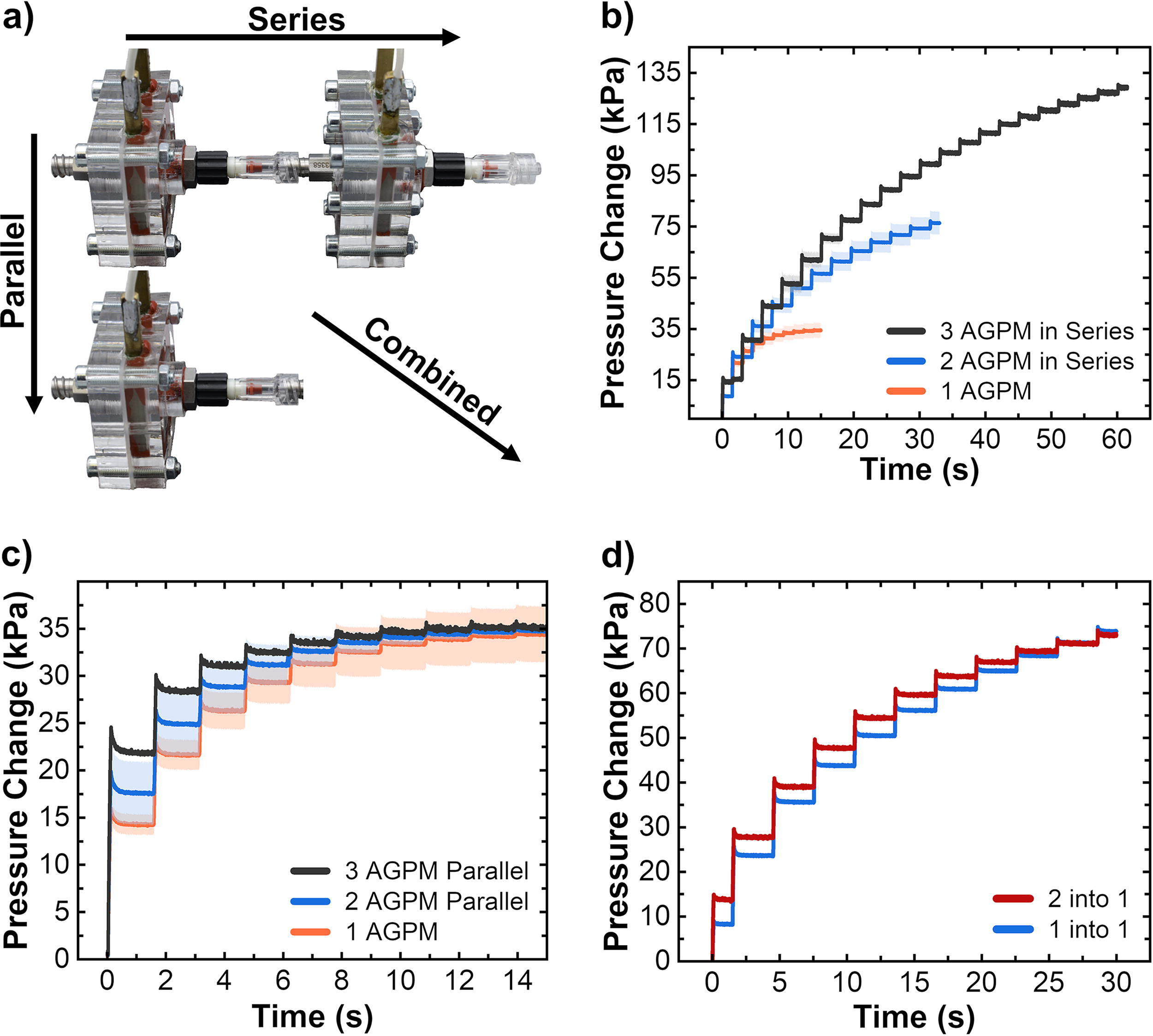
Scalability of the pressurizer concept.
Connecting multiple AGPM modules parallelly increases the pressure that can be generated per pulse. Figure 4c presents the pressure curves of two and three parallelly connected modules compared with a single system. Especially the pressure increase caused by the first pulse is significantly higher when multiple units are used parallelly. A more detailed analysis of the first 5 pulses is presented in the supplemental information (Supplementary Data S7). While a single 4 mm module generates about 14 kPa on the first pulse, this value is increased to ∼17 kPa for two and ∼21.5 kPa for three modules. However, the maximum reachable pressure is not increased. In addition, the mean power consumption of multiple parallel AGPM add up when they are operated simultaneously, which is why serial operation should be preferred when the reaction time of the system is less of concern.
As demonstrated by Figure 4d, both concepts can be combined to exploit their effects in tandem. Two parallel modules with another module in series show both, an increased pressure on the first pulses as well as an increased maximum pressure compared with a single module. By clever combination of multiple AGPMs in parallel and series a pressure generator can be created that is specifically adapted to its intended use case.
Conclusion
In conclusion, this study presents a new type of thermopneumatic pressure generator using a hierarchical network of carbon microtubes called aerographene as transducer material. Compared with the pleated or coiled wires used as transducer material in previously reported thermopneumatic systems, aerographene has a significantly higher accessible surface area and lower heat capacity. Thereby, aerographene can be rapidly Joule heated to 400°C under air. Used as transducer material in the aerographene pressurizer module (AGPM), it enables thermopneumatic pressure generation with low response times (50–100 ms) and high repetition rates (∼1 Hz). An AGPM employing 20 × 20 × 4 mm (1.6 cm3) of aerographene is able to pressurize a reservoir of ∼4.2 cm3 to around 14 kPa with a single pulse of 80 W for 50 ms. Through periodic operation of the AGPM at a frequency of 0.66 Hz, the pressure was further increased to approximately 36 kPa within just 10 s. It was further demonstrated that several AGPM can combined either parallelly or in series for improved pressure generation. Operating AGPMs in parallel results in an increased pressure generated by the initial pulse. Three parallelly operated AGPM were capable of generating a pressure ∼21.5 kPa in 100 ms. Connecting AGPMs in series and operating the alternatingly leads to an increase in the maximum pressure reached by the system. With three AGPM working in series, it was possible to pressurize 4.2 cm3 of air to almost 62.5 kPa in 15 s or 200 kPa in about 2.5 min. With most of the recently presented bioinspired pneumatic grippers operating on 0.5 kPa of pressure, having 4.2 cm3 of air at ∼200 kPa is equivalent to almost 1700 cm3 at 0.5 kPa. The AGPM should therefore be more than capable of providing the necessary pressurized air for a robot utilizing such grippers. Furthermore, the AGPM concept provides many opportunities for further optimization. For example, by using inert gas as the medium instead of air, the aerographene could potentially be heated to temperatures around 800°C or even beyond, resulting in significantly higher pressures. Improving the AGPMs ability to cool after the heat pulse by, for example, using anodized aluminum for the casing of the module, could increase the possible repetition rates at high maximum pressures. With a plethora of possible ways to combine different AGPMs it is possible to create pressure generators specifically tailored for the designated use-cases. The minimalistic design of the AGPM with only two moving parts is easy to miniaturize and maintain. The AGPM could be easily adapted to circuit boards, making the concept an excellent fit as on-board pressure generator for autonomous soft robots.
Materials and Methods
Resource availability. The tetrapodal zincoxide (t-ZnO) generated in this study will be made available in reasonable amounts on request to the corresponding author. There are restrictions to the availability of t-ZnO because of our limited production capability and our need to maintain the stock. We may require a payment and a completed materials transfer agreement if there is potential for commercial application. Large quantities of t-ZnO are available for purchase from PhiStone AG (Mielkendorf, Germany). All 3D files and schematics necessary to reproduce the devices presented in this work will be made available by the corresponding authors upon request. All other materials are available from the respective sources quoted in this section.
Fabrication of aerographene
Zinc oxide tetrapods were produced using the flame transport synthesis approach described by Mishra, Kaps et al. 18 A 2:1 mixture of Mowital B60H (Kuraray Europe GmBH, Germany) and zinc dust (Sigma-Aldrich Chemie GmBH, Germany) is placed in a furnace at 900°C for 20 min. The resulting t-ZnO particles are harvested from the crucible manually. The t-ZnO particles are compressed into 20 × 20 mm templates of various thickness with a densities of 0.3 g cm−³. Additional templates with a network density of 0.6 g cm−³ are prepared in 20 × 20 × 4 mm. The templates are sintered at 1150°C for 5 h to increase mechanical stability. The templates are then infiltrated with an aqueous dispersion of electrochemically EG. The dispersion is prepared similar as described elsewhere 19 and kindly provided by Sixonia Tech GmbH (Dresden, Germany).
The dispersion is diluted to 1.4 mg ml−1 with deionized water before being tip sonicated with 3 s pulses for a total of 10 min and 13.16 kJ using a Sonoplus HD4100 (Bandelin, Germany). The dispersion is drop infiltrated into the templates until their free volume is filled. After infiltration, the samples are dried for 4 h at 50°C. The procedure is repeated a total of seven times. The processed templates are then placed in 10% hydrochloric acid for 24 h to etch out the ZnO. The resulting aeromaterial samples are then washed three times each in deionized water and pure ethanol before being dried using EM CPD300 critical point dryer (Leica, Germany). The aerographene is then electrically conducted using brass rods and conductive silver paste (Acheson 1415, Plano, Germany) before being mounted into CNC machined sample holders. The base of the aerographene pressurizer module is sealed using highly temperature resistant silicone (Pattex Ofen und Kamin Spezial Silikon, Henkel, Germany). A silicone rubber sealing and a screwed on top lid completes the module.
Setup for rapid joule heating.
Joule heating the aerographene is performed using a self-designed rapid heating setup. For temperature measurements, a high-speed Metis H318 pyrometer (SensorTherm GmbH, Germany) is used. An EA PS9080-60 is used as power supply. Data recording and setup control are performed by an USB2537 High-Speed DAQ Board (Measurement Computing Corporation, USA) in combination with a self-programmed Python software.
Characterization of Joule-heating behavior. AGPM with 20 × 20 mm aerographene of varying thickness are Joule heated using the setup described above. The top lid is removed, and the aerographene is covered by a codial window with high infrared permeability (SFK16, VAb Vakuum-Anlagenbau, Germany).
The samples are heated to ∼400°C by applying short power pulses of 50–200 ms. The power required for each pulse length is recorded. Each sample is also heated with the energy required to heat the sample to 400°C in 100 ms but applied over 50, 150, and 200 ms. The maximum temperature reached by each pulse is recorded. Additional experiments are performed on 4 mm AGPM fabricated using aerographene with twice the t-ZnO template density (0.6 g cm−3). The experimental parameters are the same as for the 4 mm samples with standard density.
Thermographic analysis
An unsealed aerographene pressurizer module with a sample of 5 mm thickness is Joule heated with 54W—12.6V for 100 ms using the rapid heating setup described above. Infrared images and additional temperature data are recorded using a HD VarioCAM infrared camera (InfraTec, Germany). Evaluation of the camera data is performed using the thermography software IRBIS 3.1 (Infratec, Germany). A histogram of the camera temperature data is generated using a self-written Python program.
Investigation on cycling stability
To show cyclic stability of the aeromaterial, a 20 × 20 × 5 mm sample is primed by Joule heating it to ∼400°C a total five times. The sample is then left to cool for 2 min. Afterward, the sample is Joule heated to ∼400°C by repeatedly applying ∼50W—12.1V for 100 ms with a subsequent cooling period of 1400 ms. A total of 50 cycles is performed.
Pressure generation. Each aerographene module is connected to two medical check valves (Infuvalve-Braun, Germany) to form a pressurizer module. The pressurizer module is then connected to a pressure reservoir with a volume of 4.3 mL using a medical 3-way luerlock valve (Braun, Germany). The pressure reservoir is outfitted with a Type 4260A pressure sensor (Kistler Instrument Corporation, USA). The pressure generated through Joule-heating pressurizer modules with samples of a t-ZnO template density of 0.3 g cm−3 and varying thickness is measured. Based on the results of the characterization of the Joule-heating behavior (Supplementary Data S1), the applied electrical powers for each respective pulse length listed in Table 2 are chosen. The samples are pulsed a total of 10 times every 1.5 s. The pressure in the pressure reservoir is measured continuously. The experiments are also performed for 4 mm pressurizer modules of twice the ZnO template density (0.6 g cm−3) with the same parameters as the standard 4 mm modules.
Cavity and Respective Sample Volume with the Corresponding Filling Factor for AGPM Employing Aerographene of Varying Thickness
AGPM, aerographene pressurizer module.
The influence of the cooling interval between each pulse is determined by pulsing the pressurizer modules with different frequencies. Four millimeter pressurizer modules are pulsed 10 times with 45 W for 100 ms. The modules are pulsed every 1 s, 1.5 s, and 2 s, respectively.
Parallel operation of pressurizer modules. AGPM of 4 mm thickness is combined via 3-way luerlock valves before being connected to the pressure reservoir as described above. The modules are operated simultaneously at 45W for 100 ms with cooling intervals of 1400 ms. The modules are pulsed a total of 10 times. The pressure in the pressure reservoir is continuously recorded. Parallel operation of two and three AGPM is analyzed, respectively.
Serial operation of pressurizer modules. Two 4 mm AGPM are connected in series and attached to the pressure reservoir. The modules are operated alternatingly in several ratios, pumping the first module 1–5 times before pumping the second module once. Power pulses of 45W for 100 ms are applied. The cycle is repeated several times while the pressure in the reservoir is continuously recorded.
Three modules in series are operated in a 1_0_1 to 0_1_0 ratio, meaning the first and last module are pulsed simultaneously once, before the middle module is pulsed once. Power pulses of 45W for 100 ms are applied. The pressure in the reservoir is recorded continuously over several cycles.
Combined operation of pressurizer modules. Two parallel 4 mm AGPMs are connected in series with a third 4 mm AGPM and the pressure reservoir. The parallel modules are operated simultaneously once before the module in series is pulsed. All modules are pulsed with 45 W for 100 ms with subsequent cooling of 1400 ms. The cycle is repeated several times while the pressure is recorded continuously.
Demonstration of soft actuation. An AGPM employing 20 × 20 × 4 mm of aerographene is connected to a self-designed silicone soft actuator via a 3-way valve. The AGPM is supplied with 100 ms pulses with 45 W of power at a frequency of 0.66 Hz. The reaction of the soft actuator to an increasing number of pulses is recorded using a Canon 2000D DSLR camera.
Demonstration of pumping against a constant pressure. AGPM’s employing 20 × 20 mm of aerographene with a thickness of 3 mm and 4 mm, respectively, are connected to a 20 mL glass syringe with a piston diameter of 10 mm. The piston of the syringe is weight in at 29.7 g. The AGPM is pulsed 10 times at a frequency of 0.66 Hz using 100 ms pulses with the respective power values from Table 2. The resulting displacement of the piston is recorded using a Canon 2000D DSLR camera.
In addition, the air flow rates generated by the AGPM’s are determined by comparing the recorded images and applying a linear fit.
Electron microscopy
Scanning electron microscopy on several samples is performed using a Zeiss Supra 55VP with an in-lens detector.
Footnotes
Authors’ Contributions
The AGPM concept was envisioned by J.B., R.A., A.R., J.R., and F.S., R.A., and F.S. secured the necessary funding. The required resources were provided by R.A. The undertaking was supervised by F.S., R.A., as well as S.K. Project administration was handled by A.R., J.R., and F.S. The methodology for this work was developed by A.R., E.G., F.S., J.R., and M.M. Any custom software was programmed by E.G., S.K., and A.R. The investigations were carried out by A.R. and J.R. The acquired data was curated by A.R., E.G., and F.S. before being validated by A.R., J.R., E.G., and F.S. Formal analysis was performed by A.R., J.R., E.G., F.S., and R.A. The results were visualized by A.R., J.R., E.G., F.S., and M.M. The first draft was devised by A.R. in cooperation with F.S. All of the authors contributed to reviewing and editing the article.
Author Disclosure Statement
The authors declare that there is no conflict of interests.
Funding Information
The authors acknowledge funding by the

References
Supplementary Material
Please find the following supplemental material available below.
For Open Access articles published under a Creative Commons License, all supplemental material carries the same license as the article it is associated with.
For non-Open Access articles published, all supplemental material carries a non-exclusive license, and permission requests for re-use of supplemental material or any part of supplemental material shall be sent directly to the copyright owner as specified in the copyright notice associated with the article.
