




Abstract
The unique rigid-flex connection between the fin-rays and fin-surface in a bionic undulatory fin robot endows the fin-surface with both active flexibility and load-bearing capacity, enabling this robot to perform amphibious motions in underwater, terrestrial, and even marshy environments. However, investigations into dynamic modeling problems for the undulatory fin robot, considering the impact of nonlinear deformation and frictional contact on ground locomotion performance, are scarce. Given this, based on the absolute nodal coordinate formulation (ANCF), this paper presents an efficient and accurate nonlinear dynamic model for this robot to elucidate the fin’s flexible deformation and motion law. This model considers material, geometric, and boundary nonlinearities, utilizing ANCF thin plate elements and reference nodes to individually describe the fin-surface and fin-rays of the undulatory fin. Then, by using the master-slave technique, a frictional contact formulation for the fin and the ground is proposed. Furthermore, we conduct in-depth research and analysis on the formation and undulatory motion of the undulatory fin, encompassing its static deformation, static contact deformation, and frictional contact motion, and successfully obtain its responses under various conditions. Research indicates that during fin-surface motion, longitudinal sliding or a tendency for sliding at the contact points results in the undulatory fin moving in a crawling gait. The proposed theoretical model correctly captures the fin’s complex nonlinear deformations and frictional characteristics and reveals its ground locomotion mechanism, whose effectiveness and superiority are validated through numerical examples and experiments.
Introduction
Recent advancements in robotics, bionics, and new materials have fueled interest in developing bionic and flexible amphibious robots. These robots, characterized by high flexibility and environmental compatibility, combine the strengths of rigid and soft robots. Bionic flexible undulatory fin amphibious robots have become a prominent research focus. 1 The flexible undulatory fin (FUF) in aquatic organisms generates propulsion through wave-like motion. 2 This unique propulsion structure has captured the attention of researchers, prompting scholarly inquiry into the locomotion of aquatic organisms and an in-depth exploration of the propulsion mechanisms of the FUF.3–5 Scholars have found FUFs, with their high maneuverability and stability underwater, to render them highly suitable as bioinspired models for underwater robotics, thereby propelling extensive research into underwater biomimetic undulating fins.6–10 However, a recent breakthrough by the Office of Naval Research and Pliant Energy Systems has led to the design of “Velox”, 11 a robot capable of aquatic and terrestrial locomotion using FUFs. The flexible structures of such amphibious robots provide a stronger degree of flexibility, adaptability, and robustness, making them well-suited for traversing various terrains, including land and nearshore tidal flats. Consequently, these amphibious robots hold significant value in scientific, commercial, and military applications, including disaster rescue, water quality monitoring, and nearshore reconnaissance. 12
While research on underwater FUF has reached a relatively mature stage, studies on ground propulsion theory remain in their early stages. Therefore, it is imperative to establish a dynamic model for the FUF that accounts for fin-surface deformation to explore its ground locomotion mechanism and fully exploit its performance.
In the design and manufacture of FUF, Zhou et al. 13 drew inspiration from Manta Rays, leading to a bionic underwater vehicle, RoMan-II, which utilizes six fin-rays to drive flexible fin surfaces to generate thrust. Similarly, Chew et al. 14 created the propulsion mechanism and pectoral fin for their robot, inspired by Manta Rays. For bionic designs based on other FUF organisms, Low et al. 15 designed a novel biomimetic robotic fish, NKF-II, inspired by Gymnotiform swimmers, to enhance propulsion performance by mimicking the flexible fins of real fish. Uddin et al. 16 developed a single FUF propulsion robot inspired by the American knifefish. Wang et al. 17 were inspired by freshwater stingrays and designed a bionic robot with undulating pectoral fins capable of various motion control modes. Similar bionic robots include Galatea, a bionic FUF underwater vehicle designed by Simons et al., 18 a hybrid underwater robot with four rotors and bionic FUFs for propulsion designed by Zeng et al., 19 and a batoid-inspired flapping robot made of soft materials designed by Liu et al. 20 Overall, despite significant advancements in the structural design of underwater FUFs, they remain unsuitable for terrestrial propulsion.
Recently, the robot “velox” emergence has sparked interest in amphibious FUF designs. Yin et al. 21 applied a similar structure to the robot’s sides as amphibious propulsion mechanisms, inspired by the Gymnarchus niloticus. Zhang et al. 22 designed a fixed single FUF device for ground propulsion force testing. Xia et al. 23 developed a combination of flexible thin-film fins and curved springs for balanced flexibility underwater and rigidity on land but with a relatively complex design. The application research of the FUF in amphibious environments is gradually developing, yet its vast potential warrants in-depth exploration and investigation of the FUF’s amphibious structural design.
On the modeling and analysis level of FUF, much of the focus has been on numerical simulations in underwater environments. Zhou et al. 24 developed a 2-degree-of-freedom structural and kinematic model using a ruled surface model. However, most studies in the hydrodynamic theory of the FUF motion have employed this model as the motion equation for the fin-surface, neglecting its actual flexible deformation. Sfakiotakis et al. 25 proposed a fluid resistance model for the FUF, combining it with a 3D flapping kinematic model to determine its applicability. This fluid resistance model has been widely adopted for modeling the underwater dynamic characteristics of the FUF,26–30 essentially treating the surface microelements of the fin as a basic model resembling a fluid resistance formula.
With the improvement of computer technology, computational fluid dynamics has become the primary approach for studying bionic propulsion. Wei et al.
9
evaluated the hydrodynamic performance of the FUF propulsion using the Tethered Model (TM) and Self-Propelled Model (SPM) strategies. Hu et al.
31
numerically studied four basic modes of the FUF using the Shear Stress Transport (SST) turbulence model. Ren et al.
32
utilized a
Initially, researchers primarily focused on modeling and analyzing the FUF underwater using a ruled surface kinematic model. However, limited research has been conducted on the flexible deformation and ground locomotion performance of the FUF. Early studies utilized the micro-rigid body method to develop a ground-thrusting model for the FUF. 37 Xia et al. 23 performed a fundamental mechanical analysis on the FUF formed by a combination of thin-film fins and curved springs. Nevertheless, using the micro-rigid body method to model flexible bodies and neglecting fin-surface deformation may lead to inaccurate results in analyzing the dynamic characteristics of the FUF. Zhang et al. 22 analyzed the ground locomotion principle and mechanical modeling of the FUF based on the ruled surface model. However, this model disregarded the effects of fin-surface material deformation. It’s important to note that this idealized state can only be achieved under specific constraints.
Overall, little attention has been given to considering the material characteristics of the fin-surface in the motion modeling of FUF. The study of fin deformation in the FUF remains an unresolved challenge. Addressing the issues exposed in the research on the FUF, such as accurately and effectively considering the deformation of the fin and establishing corresponding ground dynamics models, still needs more extensive investigations; this is precisely the area of particular interest to us.
This paper proposes an effective dynamic model for the undulatory fin robot based on the ANCF. This model considers fin deformation, material properties, and frictional contact with the ground. This paper is organized as follows: (1) The Materials and Methods section elaborates on the structural characteristics of the FUF and establishes the nonlinear dynamic equation for its motion. (2) The Numerical Examples section presents a comparative analysis of numerical cases to provide preliminary validation of the effectiveness of the dynamic model. (3) The Experimental Investigation and Comparative Analysis section conducts static and dynamic simulations of the FUF, compares and analyzes the results with experimental data, and further validates the method’s effectiveness. (4) The Conclusions and Further Work section draws some conclusions and prospects.
Materials and Methods
Specific structure of a FUF
Inspired by the propulsion mechanism of the ribbon fin in black ghost knifefish (Fig. 1A), 38 we designed an undulatory fin amphibious robot (Fig. 1B) with a pair of FUFs arranged along both sides of the body and five fin-rays used to achieve a complete waveform. Building upon previous work, 21 this paper aims to investigate the nonlinear deformation of the FUF, the frictional contact between the fin-surface and the ground, and the dynamic response of the FUF.

Inspiration and structural design of the FUF.
The study focuses on a FUF made of rubber material, which is constrained at specific joints (i.e., the connection joints between the fin-rays and the fin-surface) to achieve the FUF configuration (Fig. 1C). Therefore, the parameters of the annular sector thin plate are typically inferred from this configuration.
As shown in Figure 1C, the inner and outer radii of the annular sector plate are
The initial shape of the plate can be uniquely described by
The oscillating motion of a fin-ray can be described as follows:
21
This paper sets
It can be understood that
Figure 1D illustrates the mechanical configuration and corresponding coordinates of the single-sided FUF. Firstly, the oscillating ray is rigidly connected to the actuator and oscillates around the baseline. The fin-surface is fixed onto the fin chuck. The oscillating ray and fin chuck form a rigid fin-ray. Here, O-XYZ is the base coordinate system of the FUF, describing the body’s motion.
As illustrated in Figure 1, forming a FUF and its application in ground propulsion mechanisms entail a series of mechanical challenges, including material, geometric, boundary, and frictional contact nonlinear modeling. Addressing these challenges, this paper proposes an efficient and accurate nonlinear dynamic model based on the ANCF framework.
Nonlinear dynamic modeling
The fin-surface possesses a thin plate-like structure, which can be modeled using three-node triangular thin plate elements, as shown in Figure 2A. The absolute position vector of an arbitrary point P on the mid-surface can be interpolated as:

Description of the ANCF thin-plate element and ANCF-RN
The concept of the ANCF reference node (ANCF-RN), as proposed by Shabana,41,42 introduces a node that is not directly associated with any finite element. Therefore, ANCF-RN can be used to define rigid fin-rays as components of a FUF mesh, as shown in Figure 2B.
This paper introduces a gradient-deficient ANCF-RN method for describing rigid fin-rays. Similar to the ANCF element, the absolute position vector of any point
Let
Let
The detailed derivation of the above theoretical model, element forces, and constraint settings can be consulted in Supplementary Appendix SA1, and the Gaussian quadrature integration technique is used to compute the above element force vectors and their derivatives.43–48
The nonlinear dynamic Eq. (8) can be solved by combining Generalized-

Computational flowchart for the dynamic analysis of the FUF. FUF, flexible undulatory fin.
The meanings of the variables involved in Figure 3 are explained appropriately here.
This study aims to investigate the nonlinear dynamic characteristics of the FUF in ground contact based on the actual deformation of the fin-surface. As the mechanical properties of the fin-surfaces on both sides of the FUF robot are similar during motion, the study focuses solely on one side of the fin-surface. 22 Simultaneously, Considering the periodic nature of the waveform formed by the single-side fin-surface, employing a complete waveform allows for the simulation of all states of the fin-ground contact.22,23 Therefore, subsequent simulations and experiments using a FUF with a complete waveform can accurately analyze the ground motion characteristics of the fin-surface, thereby improving simulation efficiency and simplifying the complexity of experimental design.
Numerical Examples
In this section, numerical simulation methods are employed to compare with numerical examples from other literature, providing preliminary verification of the accuracy and effectiveness of the proposed dynamics model. Firstly, the effectiveness of the ANCF element is evaluated by utilizing a rectangular thin plate pendulum (Fig. 4A). The ANCF element used in this paper is contrasted with the thin plate element proposed by Shabana in reference. 45 The simulation parameters are consistent with those stated in the reference. Figure 4A displays the configurations of the pendulum at different time instances. As depicted in Figure 4B, the obtained results demonstrate good agreement with those presented in the reference, thereby verifying the effectiveness of the adopted ANCF element.

Comparison of numerical examples.
The second numerical example is from reference, 47 aiming to verify the friction contact model through the contact friction between two thin plates. Detailed settings can be found in the reference, while this paper directly compares the results. Figure 4C and D depicts the time histories of displacement and acceleration of the upper plate, respectively. The simulation results are consistent with the reference, demonstrating the stick-slip characteristics of the frictional contact model, thus validating the correctness and effectiveness of the model.
Experimental Investigation and Comparative Analysis
To capture the actual motion law of the FUF and verify the proposed theoretical model, an experimental setup is constructed based on the approach outlined in reference 52 to evaluate its motion characteristics. Corresponding deformation and motion experiments are conducted on the experimental platform shown in Figure 5. The experimental and simulation parameters are detailed in Table 1.

Experimental platform for measuring the deformation and motion of the FUF. FUF, flexible undulatory fin.
Description of Specific Parameters
The motion of the FUF is controlled by five joint motors (DM-J4310-2EC). These motors control the fin-rays’ oscillation, thus governing the motion of the fin-surface. The FUF is fixed to the baseplate of the experimental platform. The thrust and torque generated during the motion of the FUF are collected by a six-axis force sensor (ATI DAQ F/T USB). A slider is used to adjust the height of the FUF experimental setup above a floor that simulates the ground. The data collected by the sensor are processed by a data acquisition box (NI-USB 6251) and transmitted to the computer via a USB port.
A series of red markers are attached to the outer edge of the fin-surface, and the deformation and motion videos are recorded by a high-definition camera (Nikon Z5 and Viltrox AF 85/1.8Z Lens) installed on a tripod. A ruler is placed on the glass plate facing the FUF to observe and calibrate the position changes of the markers during the FUF deformation and motion. Ensure that the camera’s perspective, the position of markers, and the glass plate are parallel to each other, and the markers are very close to the glass plate. Then, utilize the calibrated parameters of the camera to perform undistortion on the acquired image, and use image data extraction software (WebPlotDigitizer) to extract data from the processed image.
The fin-rays’ oscillating motion is calculated according to Eqs. (2) and (3).
Static deformation of the FUF
In this experiment, the annular sector plate is fabricated with the design parameter
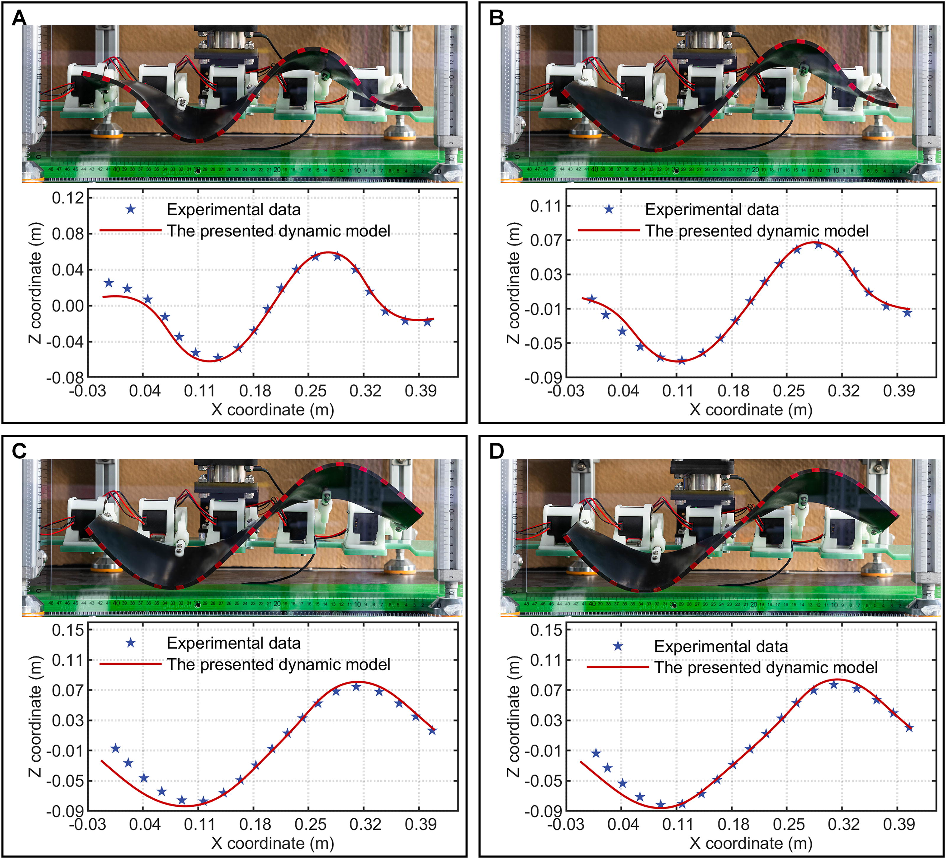
Experimental and simulated deformation results of the FUF under different amplitudes.
By observing Figure 6, the theoretical and experimental results of the FUF’s waveform state and outer edge deformation exhibit good agreement. Although there is a relatively significant error between the theoretical deformation and the experiment for the leftmost section of the FUF, this could be attributed to the initial pre-stress caused by the hardening of the fin material. However, this error, which ranges from 2.5% to 7.5% relative to the overall size (L0 = 0.4m) of the FUF, does not significantly affect the dynamic characteristics analysis of the fin surface.
Static contact of the FUF on the ground
In this experiment, the same annular sector plate is used to conduct static contact experiments of the FUF under different ground contact pressures (

Experimental and simulated deformation results of the FUF under different ground contact pressures.
The Absolute Error of the Baseline Height
It is worth noting that although the waveform of the ground contact section undergoes significant changes, the waveform of the fin surface above the baseline changes tiny. It indicates that the ground locomotion performance of the FUF is primarily influenced by the waveform below the baseline while having a minor impact on the waveform above the baseline. Optimizing the waveform of the section above the baseline can improve the system’s energy output.
Dynamic motion of the FUF on the ground
In this experiment, the same plate is used to conduct motion experiments of the FUF in contact with the ground under amplitude

The motion status of the FUF at different moments.
In order to understand and grasp the motion characteristics of the FUF, we have depicted its deformations along the outer edge and analyzed its gait. Figure 9 demonstrates the different deformation shapes of the fin-surface at specific moments through dynamic simulations and experiments. As shown in Figure 9A, the FUF undergoes undulatory motion along the positive X-axis, with its waveform being transmitted gradually in the order of a -> b -> c -> d -> e (corresponding to 0, 2, 4, 6, and 8 s). This undulation pattern is achieved through the cyclic oscillation of the fin-rays. The alternate generation of contact areas will result in the FUF moving forward in a crawling gait.
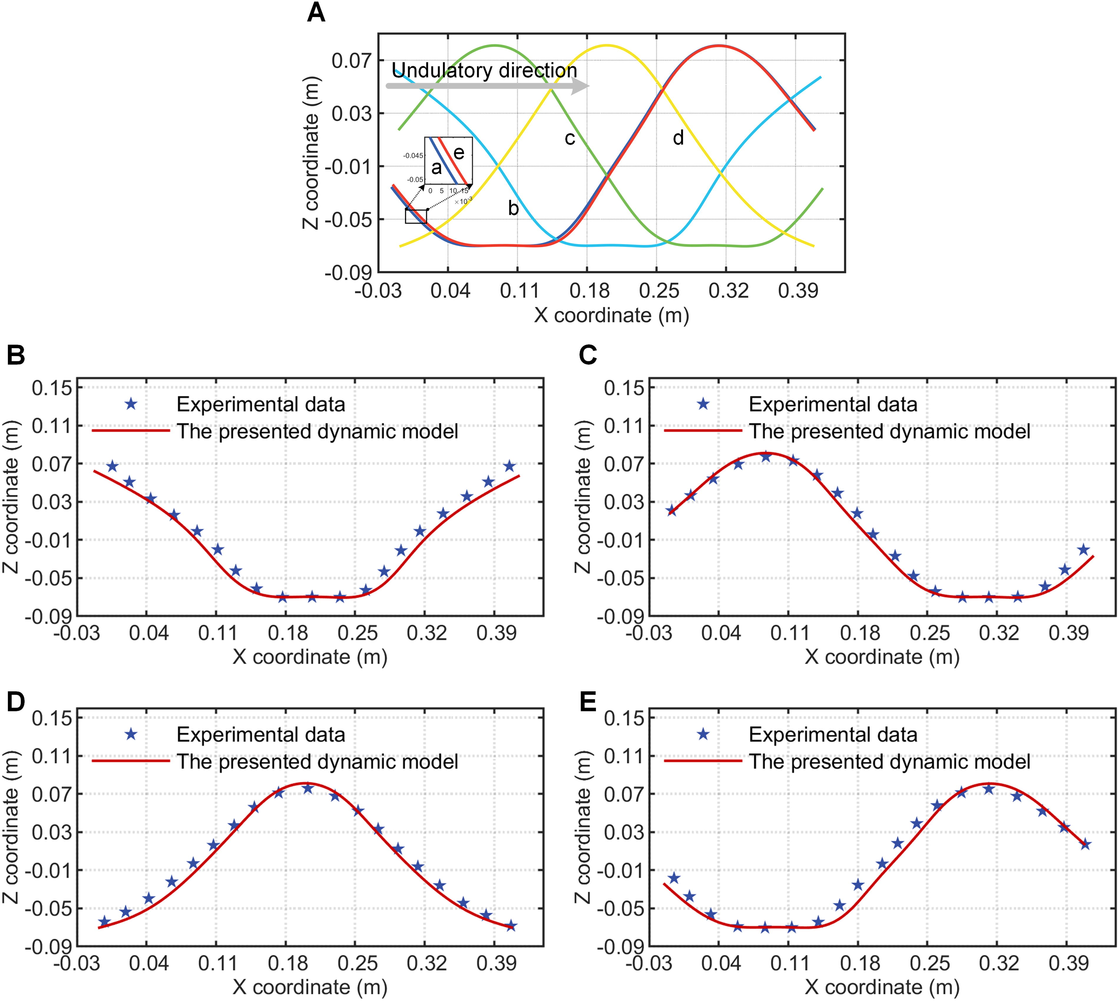
Experimental and simulated deformation results of the FUF at various moments.
The theoretical curve shapes shown in Figures 9B–E correspond sequentially to the curve sequence displayed in Figure 9A: b, c, d, and e. It can be observed that the deformation shapes obtained from the proposed dynamic model are in good agreement with the experimental results.
To analyze the friction mechanism between the fin surface and the ground, we have depicted the displacement comparison results of the marked point M (Fig. 8A) for both simulation and experiment and analyzed the frictional state during the FUF motion. Figure 10A shows the temporal variation of point M’s X and Z coordinates, with the green solid line indicating that point M is in contact. It can be observed that the Z-coordinate variation of point M is the oscillatory response of the fin-ray, exhibiting waveform changes. Although the rigid fin-rays are constrained to oscillate within the YZ plane, the deformation of the fin-surface results in the displacement of point M along the X-axis. When point M is in contact with the ground, its X-coordinate decreases over time due to the motion of the fin surface, indicating that the movement of the contact point is opposite to the undulatory motion of the fin surface. As a result, relative motion occurs between the contact point and the ground, giving rise to frictional force, whose direction aligns with the fin-surface’s undulatory motion (Fig. 10C). In other words, the undulatory motion of the fin-surface causes relative motion or a tendency of relative motion between the contact point and the ground, thus generating frictional forces that enable the FUF to move on the ground.

The trajectory of point M and the ground friction results of the FUF.
Figure 10B presents point M’s simulated and experimental trajectories in the XZ plane. It can be observed that the trajectory of point M exhibits an “8” pattern, and the width of the lower half of the trajectory is larger than that of the upper half due to the compression from the ground. As indicated by the previous analysis, the deformation of the upper half is less affected by the ground. Thus, its width is mainly constrained by the rigidity of the fin-rays, whereas the ground and the rigidity of the fin rays concurrently influence the lower half.
Figure 10C and D depicts the longitudinal (in the X-direction) and lateral (in the Y-direction) friction forces experienced by the FUF against the ground. In Figure 10, the difference between transverse curves is due to the oscillatory nature of the ANCF model. This nature is the direct effect of the coupled deformation modes of the ANCF model compared with the experimental result. Furthermore, the error in the results of Figure 10C and D is also influenced by the simplified schemes adopted in the ideal model and the neglect of the viscosity effect between the fin and the ground. The absolute error of the mean friction force is calculated based on experimental and simulated results, as shown in Table 3. The results demonstrate that the frictional contact model exhibits high accuracy.
The Absolute Error of the Mean Force
The results from Figures 6 to 10 demonstrate that the proposed dynamic model exhibits high precision in capturing the overall configuration variations of the FUF, the motion gaits, and the contact states. The theoretical and experimental results exhibit an almost identical consistency and tendency, highlighting the effectiveness of the proposed method for modeling the undulatory motion and contact friction mechanics of the FUF.
The effects of friction coefficient on the FUF’s movement
The previous analysis shows that the friction between the FUF and the ground is the fin’s primary source of thrust generation. However, varying ground surfaces lead to changes in frictional characteristics. Therefore, it is crucial to analyze the effect of different friction coefficients on the dynamic performance and state of the FUF. The effectiveness of the FUF’s dynamic model was validated through a comparison of simulations and experiments in the preceding section. This section will employ this model to analyze how different friction coefficients affect the FUF’s motion, as illustrated in Figure 11.

Frictional forces and waveforms of the FUF at different friction coefficients.
The simulation parameters are consistent with those in the previous section, with the baseline position of the FUF fixed, considering only changes in the friction coefficient. The simulation results from the final cycle are analyzed. The friction coefficient
Overall, variations in the friction coefficient impact both the dynamic performance and the waveform state of the FUF on the ground, albeit to different extents. Compared to the contact area between the fin and the ground, changes in the friction coefficient have a more significant effect on the ground thrust of the FUF. Therefore, increasing the friction between the FUF and the ground can enhance its propulsion performance.
Conclusions and Further Work
Using the ANCF framework, we propose an effective nonlinear dynamic model for the undulatory fin robot that accounts for material, geometric, boundary nonlinearities, and the frictional contact between the FUF and the ground. This model enables the prediction of FUF deformation and its stick-slip motion during ground contact, which has been evaluated through numerical and experimental methods. Two numerical examples for preliminary verification and three experiments are conducted to validate the proposed theoretical model further. The experiment-simulation comparison demonstrates good agreement in their consistency, with a deformation error ranging from 2.5% to 7.5%, indicating the effectiveness of the theoretical model. Then, we conduct a focused analysis of the motion state of the contact point and the frictional force within the contact area. The experimental mean longitudinal frictional force is 1.8185N, while the theoretical value is 1.8856N, resulting in an absolute error of 0.0671N. This error result demonstrates the high precision of the adopted frictional contact algorithm. Additionally, we provide a detailed explanation of the gait law and motion mechanism of the FUF and analyze the effects of the friction coefficient on the dynamic performance and waveform characteristics of the FUF.
The main contributions of this paper are as follows: (1) The flexible deformation of the FUF and its frictional contact with the ground are considered for the first time, and innovatively applying the ANCF and ANCF-RN for FUF description and integrating a multi-point contact model with the Coulomb friction model to conduct nonlinear dynamic modeling and intensive analysis of the undulatory fin robot; (2) the proposed dynamic model can not only simulate the undulatory motion of the FUF but also delineate its overall configuration changes, deformation distribution law, and nonlinear frictional contact behavior; (3) the theoretical results are comparable to the experimental ones in the aspect of the deformed shapes, contact state, and mean frictional force; through experiments and simulations, the motion mechanism and gait of the undulatory fin robot have been elucidated, validating the effectiveness and superiority of the dynamic model. This research will contribute to the structural optimization design of undulatory fin robots, fully enhancing their locomotion performance.
In future work, we will focus on investigating the actual motion of FUFs on complex terrains (such as rough ground, gravel roads, slippery ground, or soft soil) and underwater. Using the proposed model, we will analyze the dynamic performance and waveform characteristics of the FUF in different environments, and conduct corresponding experiments to validate the applicability of the model.
Footnotes
Authors’ Contributions
Y.Z.: Conceptualization (lead); Writing—original draft (lead); Methodology (lead); formal analysis (lead); Writing—review and editing (equal). Q.H.: Review and editing (equal). L.S.: Software (lead); Writing—review and editing (equal). C.J.: Methodology (lead); Writing—review and editing (equal). T.Z.: Conceptualization (supporting); Writing—original draft (supporting); Writing—review and editing (equal). S.L.: Conceptualization (supporting); Writing—original draft (supporting); Writing—review and editing (equal). X.S.: Conceptualization (supporting); Writing—original draft (supporting); Writing—review and editing (equal).
Author Disclosure Statement
No competing financial interests exist.
Funding Information
This research is supported by the Fund for “the

References
Supplementary Material
Please find the following supplemental material available below.
For Open Access articles published under a Creative Commons License, all supplemental material carries the same license as the article it is associated with.
For non-Open Access articles published, all supplemental material carries a non-exclusive license, and permission requests for re-use of supplemental material or any part of supplemental material shall be sent directly to the copyright owner as specified in the copyright notice associated with the article.
