




Abstract
Achieving strong adaptability and high-load capacity for small-scale soft robots remains a challenge in current robotics engineering. In this study, inspired by a snail movement, we developed a soft crawling robot capable of controllable locomotion and carrying a load of 204 g—7.7 times its own weight—using just one single motor for robot control. The robot measures 7.6 cm in length, 3 cm in width, and 2.5 cm in height, with a total weight of 26.5 g. The anisotropic friction mechanism on the robot’s bottom, comprising a soft origami-based pad and asymmetrical sawtooth structure, enables its strong adhesion to stick to and simultaneously crawl (transitional adhesion) on many surfaces. This design allows the robot to move at speeds up to 3 mm/s and climb a slope of 35° inclinations, also making it suitable for various uneven terrains. Additionally, the robot has enhanced cross-environmental capabilities due to its ability to glide on the water. This research advances the development of relatively simple small-scale single-actuator robots, providing insights into their potential for flexible movement, high-load capacity, and potential swarming behavior.
Introduction
Soft robots, often inspired by natural organisms, are highly adaptable and valuable for their missions in complex environments. 1 Current research on small-scale soft robots has shown impressive locomotor capabilities, including crawling, running, jumping, wall climbing, and swimming.2–8 Steering motion, crucial for trajectory control, typically requires multiple actuators in most soft robots, leading to increased size and volume, which may reduce their mobility. 9 However, soft robots powered by a single actuator tend to have lower drive power and smaller sizes, presenting challenges in steering control for independent movement and supporting only limited payloads.10–12 Achieving large load capacity and autonomous flexible motion with minimal mechanical configurations in such robots remains a significant challenge.
In recent years, soft crawling robots utilizing such technologies as dielectric elastomers,13,14 liquid crystal elastomers (LCEs),15–17 shape memory alloys (SMAs), 18 piezoelectric materials,19,20 and chemical reactions 21 have shown outstanding untethered performance. The advantages of such robots include their compact size, high motion flexibility, and robustness, although they typically require multiple actuators for steering. In contrast, research on motor-driven soft crawling robots is less well developed due to underactuated driving. Some researchers have achieved crawling functions using only one motor for the control, but these robots lack the ability to steer. 22 Those robots that can steer with multiple motors are generally larger, often exceeding 10 cm in size, and are considerably heavier.23–28 Meanwhile, some robots that can either steer with a single motor 11 or handle substantial loads 29 have rigid structures that are prone to damage due to their stiff materials.
We introduce a compact, single-motor-driven steering soft crawling robot. Inspired by the snail crawling motion, our robot achieves steering through differential speeds on its two sides during the retracted and extended gait. Measuring just 7.6 cm in length, it can smoothly navigate a variety of rough surfaces. Thanks to its powerful crawling mechanism, the robot can stably carry a load of 204 g—nearly eight times its own weight. The untethered soft snail robot demonstrates its crawling ability on several unconstructed terrains, such as inside pipelines, on plastic mesh, through lawns, and on uneven ground. Remarkably, it can also glide and actively steer on water using the same locomotion mechanism. This robot showcases the advanced adaptability among current single-actuator soft robots and presents a novel promising bionic platform not only to learn more about the biomechanics of snail locomotion, but also to potentially use such simple but strongly capable robots for the future development of robotic swarms with collective behavior.
Materials and Methods
The materials of this robot motion system mainly include silicone, polyimide (PI), and carbon fibers. Silicone (3 mm thick) is made from Ecoflex-0030 material by the mold casting method. During the production process, Ecoflex-0030 (Shenzhen Hongyejie Technology Company, Shenzhen, China) silicone agent (A) and curing agent (B) were thoroughly mixed in the mold and then cured at 60°C for more than 40 min in the holding tank. PI parts (0.15 mm thick) were processed using a cutting machine (Silhouette CAMEO3, Lindon, UT, America), while carbon fiber parts (0.5 mm thick) were processed on a laser processing machine (MRJ-UV-C20, Chengdu Myriad Laser Technology Company, Chengdu, China). The cut PI parts were folded to form an anisotropic friction mechanism with asymmetrical sawtooth structure (see the “Fabrication” section).
The robot actuator is a DC motor equipped with a gearbox with a reduction ratio of 1:118 and weighs about 13 g (1218-N20, Shenzhen Tianqu Electronics Company, Shenzhen, China). The control system mainly consists of a control board, a battery, and a self-locking switch. The control board is controlled by the nrf52832 SoC (Nordic, Trondheim, Norway) and utilizes BLE to communicate with the host computer. We can remotely control the rotation direction and speed of the motor via a custom-written app from the cell phone. The battery capacity is 100 mAh (lithium battery 401119, Shenzhen Huaze Battery Technology Company, Shenzhen, China), and the total weight is 1.45 g. The winding wheel is made by 3-dimensional printer (Formlabs 3, MA, America) and has a diameter of 10 mm. The driving wire material is made of nylon wire and carbon wire, flexible and resilient (ϕ0.165 mm fishing wire). During the assembly process, the individual parts are held together by adhesive tape (3M300LSE-9495LSE, MN, America).
Results
Robot design and working principle
Figure 1 shows an optical image of the 7.6 cm prototype robot and a snail alongside a coin. The silicone features valley and peak folds that facilitate bending and deformation during movement. Figure 1D shows the similarity of the steering mechanisms of a land snail and the prototype robot. Our observations and experiments indicate that land snails crawl by muscle-generated waves along their foot bottom. If the wave generated on the left foot side moves faster than that on the right, the snail turns right, a concept that was biologically inspired by the development of the robot steering mechanism.30–32 The steering principle of the robot is achieved by the differential contracting and stretching motion of the two sides of its body. 33 As shown in Figure 1Di, during the right steering of the snail, the contracting speed of the left side of the posterior part of the pad is faster than that of the right side of the posterior part of the pad (Vs1 > Vs2), meanwhile the stretching speed of the left side of the anterior part of the pad is also faster than that of the right side of the anterior part of the pad (Vs3 > Vs4). Figure 1Dii shows the similar right-turning processes of the prototype robot. The rear part contracts and the front part stretches with two differential speeds on two sides of the robot (Vr1 > Vr2 and Vr3 > Vr4). Figures 1Diii and iv show the left-turning strategy of the snail and prototype robot, respectively. In the left turning, the relationships between the speeds on two sides are opposed to those of the right turning. It is noted that the prototype robot uses one motor to achieve controllable locomotion. The untethered robot weighs 26.5 g and has dimensions of 7.6 cm (length) × 3 cm (width) × 2.5 cm (height).

The prototype robot and its snail-inspired steering mechanism.
Fabrication
Silicone pad
The robot body is made of a silicone structure using Ecoflex-0030 material. First, the silicone agent (A) and curing agent (B) of Ecoflex-0030 are mixed and stirred evenly at a 1:1 ratio. The mixture is then poured into a premade stainless steel mold (Fig. 2Ai) and cured at 60°C for 40 min in a thermostat cabinet. After curing, it is removed for later use (Fig. 2Aii). The overall dimensions are 7.6 cm in length, 3 cm in width, and 3 mm in thickness.
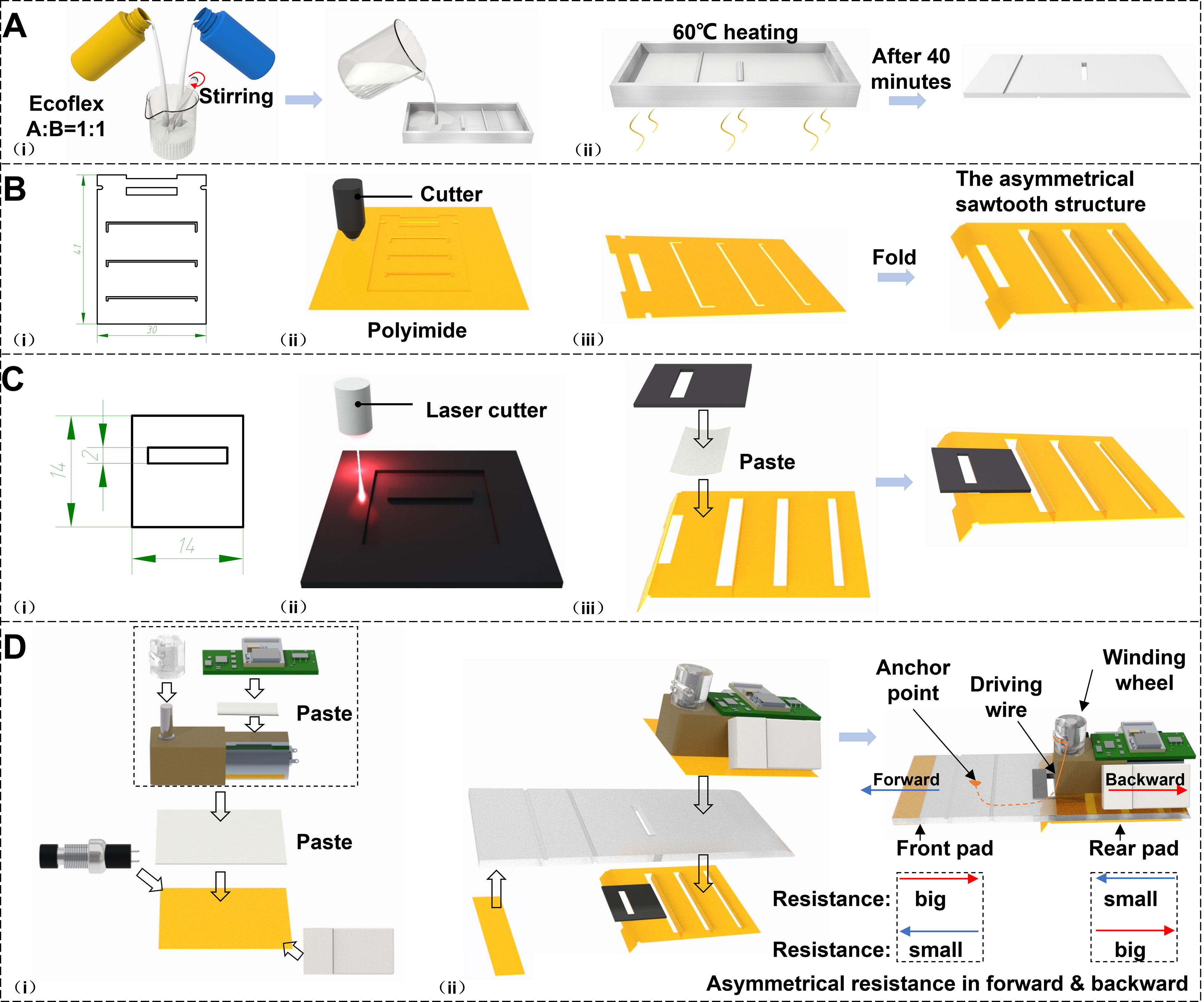
Fabrication of the robot parts and assembly processes of the robot.
Slider base
The robot’s slider base consists of 0.15 mm thick PI and 2 mm thick carbon plate. The PI structure is defined and manufactured on a vinyl cutter (Silhouette CAMEO3) (Fig. 2Bi, ii). After cutting a PI structure, the pre-set foldable PI parts are folded from left to right, decreasing in height sequentially to ensure good rigidity and reduce friction with the ground. The base plate forms an angle with the ground (Fig. 2Biii). The carbon plate structure, defined in AutoCAD software, is manufactured by a laser cutter (Fig. 2Ci, ii). Rectangular slots are used as positioning marks, and the cut carbon plate structure is taped together with the PI structure to form the robot’s baseplate structure (Fig. 2Ciii).
Assembly
First, the 3D-printed winding wheel is installed on the motor shafts via a press fit. The control circuit board is then mounted above the motor, and the entire motor assembly is taped onto a PI structure measuring 33 mm in length and 30 mm in width. The battery and the self-locking switch are taped and fixed on either side of the motor (Fig. 2Di). Given the smooth PI surface and the silicone surface’s property to adhere easily, the assembly from Figure 2Di can be directly taped to both the top and bottom of the silicone body, using the rectangular slots as alignment marks. Finally, the driving wire is wound and fixed between the two creases of the silicone and around the winding wheel, thus completing the assembly of the entire robot (Fig. 2Dii). The resistance configurations of front and rear pads in forward and backward movement are shown in Figure 2Dii. The robot’s front pad encounters less resistance moving forward than backward during the pulling and relaxing of the driving wire controlled by the motor’s rotation, while the rear pad has the opposite behavior.
Locomotion analysis
The motor rotation gaits of the robot’s locomotion (turn right, turn left, and forward) are listed in Figure 3. The control gaits are represented by the angles of the motor’s clockwise and counterclockwise rotations. The zigzag-forward crawling cycle of the robot includes one left turn and one right turn, taking approximately 6 s in total (Fig. 3A–E). In the resting state, the driving wire is situated at the center of the silicone and is in a relaxed state. The optical image and its corresponding schematic views of the resting state are shown in Figure 3Ai–iv, respectively. Figure 3Bii shows that when the motor rotates counterclockwise for one complete turn, the right side of the front pad is anchored to the ground substrate, while the left side of the front pad contracts backward by the driving wire, thereby rotating counterclockwise by a certain degree (α); at the same time, the right side of the rear pad is fixed while the left side of the rear pad contracts forward by the driving wire, thus rotating clockwise by a certain angle (β) (Fig. 3Bii). This movement is facilitated by the winding wheel, which tightens the driving wire and causes it to slide to the left due to the wheel’s counterclockwise rotation. The front pad with the silicone body bends along the creases and tends to slide backward (Fig. 3Biii). However, due to the downward component of the force in the Z–Y plane (i.e., a downward pressure on the front pad) and the strong viscosity of the silicone pad, there is significant friction with the ground that prevents backward sliding. Nevertheless, the driving wire position of the front pad is always lower than the driving wire position of the rear pad, thus creating a combined force of tension along the wire that will fold the front pad forward, and its component of the force in the Z–X plane will lift the left side of the front pad, causing the silicone pad to bend up (Fig. 3Biv) and creating high friction in the red shaded area shown in Figure 3Bii. Consequently, the silicone pad on the side with lower friction slides inward, resulting in the left side of the front pad contracting faster than the right side.

Principle of crawling motion of the soft robot and motor rotation gaits of locomotion.
Then, when the motor rotates clockwise, the tension force on the driving wire is released. The front pad recovers to its original rest position due to its elasticity, and the front pad rotates to the right by a certain angle (β), as shown in Figure 3Cii. This process is achieved by the PI-made slider at the bottom of the silicone pad, which allows the front leg to smoothly slide over the ground to return to its resting state. The PI slider causes asymmetrical friction force in clockwise and counterclockwise rotation of the winding wheel. During the process of the front pad recovering from bent to flat, the friction on the right side is greater than on the left, since the left side of the front pad is mostly bending up while the right side is in full contact with the ground substrate (Fig. 3Civ). Thus, the left side extends faster, which results in the robot’s right steering. Eventually, the front pad fully extends forward to the right (Fig. 3Cv). Similarly, the principle of the robot’s left steering is demonstrated in Figure 3D and E.
For the rear pad during motion, the opposite is true: The rear pad has low friction during contraction and high friction during extension. The asymmetrical sawtooth structure of the PI base plate forms an anisotropic friction mechanism that plays a major role in effectively realizing the crawling motion.34–36 During contraction, the component force of the combined tension force along the wire in the Y-direction causes the rear pad to contract forward, and the component force in the Z-direction causes the left side of the rear pad to be lifted upward by an angle (φ°), as shown in Figure 3Fii, in which the rear pad as a whole can be lifted easily because of the larger torque force of the motor and the carbon plate increasing the local rigidity of the rear pad, which reduces the sliding friction of the rear pad when it moves forward, thus resulting in the contraction velocity of the left side of the rear pad is greater than that of the right side as described above. During stretching, the rear pad generates a larger friction force in the backward tendency, which prevents the robot from sliding backward, as shown in Figure 3Fiii.
The design of the origami silicone pad is an indispensable factor for the robot’s stable crawling. Using ABAQUS analysis, we simulate the deformation of the front pad, as shown in Figure 4Ai. Figure 4Aii indicates the normal contact force from left to right gradually disappears, meaning that the friction on the left side of the front legs gradually decreases, thus causing twist like that depicted in Figure 2Bii. Also, the very front of the silicone base contacts the ground with a significant normal force, hindering the recovery of the front pad, which underlines the necessity of the PI slider. Further experimental comparative analysis shows that the robot with crevices (similar to hinges) in its front pad has higher crawling efficiency. As shown in Figure 4B, the silicone-based front pad with crevices (like origami structure) along the hinges, making the deformation shape easy to control. However, as shown in Figure 4C, the silicone-based front pad without crevices deforms in an irregular distorted shape. Comparatively, the angle γ1 between the direction of the pulling force and the Z axis in the noncrevice silicone structures is significantly greater than that (γ2) in the pad with crevices, resulting in a smaller normal force exerted by the pulling force on the silicone front pad, thus generating less friction and causing the front pad of the robot to slide easily, significantly shortening the crawling distance per cycle compared with the robot with origami structures, weakening the overall crawling performance (Supplementary Movie S1).

Analysis of the origami-based front pad.
Simplified locomotion model
We develop a simplified physical model that defines the relationship between the motor’s rotation angle θ and the robot’s turning angle β. Taking a right turn as an example, Figure 5A illustrates the robot’s locomotion details in one driving cycle (around 3 s) with key geometry parameters. The completed control gaits can be simplified into three stages: from the initial state (i) to the motor rotating counterclockwise by an angle θ (ii) and finally to the motor rotating clockwise by θ to return to the starting position (iii). It is noted that the start of the driving wire should be biased to the left side of the motor’s winding wheel during (i). In (ii), the biased pull of the driving wire causes elevation on the left side of the robot to exceed that on the right, resulting in the front and rear pads twisting by angles α and β, respectively. The robot’s locomotion on substrates of acrylic (high friction, μ = 1.7) and paper (low friction, μ = 0.6) is compared in (ii). High friction will lead to a relatively small rotation of the body (α is around 0 and β is small), a fixed front pad, and a large forward displacement of the rear pad, while low friction will result in a relatively large rotation of the body (α and β are large), a slipped front pad, and a small forward displacement of the rear pad. In the recovery process (iii), the rear pad experiences greater frictional resistance than the front pad, causing the rear pad to remain fixed while the front pad rotates by α, returning the robot’s body to a flat state, where all elevation disappears. Therefore, the motor’s counterclockwise rotation by θ, followed by a clockwise return, causes the robot to turn right by β. Similarly, the robot’s left turn is caused by the motor’s clockwise rotation followed by a counterclockwise return. Specifically, after the motor rotates by θ, the length of the wire is shortened. The length change ΔL is given by the following equation:

Simplified model of a right turn and characterization.
Where L represents the distance from the anchor point (labeled in Fig. 5A) to the biased position (labeled in Fig. 5A) in the initial state (i),
Where R is the radius of the winding wheel (5 mm). Therefore, the relationship between the motor’s rotation angle θ and the robot’s turning angle β can be approximately fitted by cubic curves, as shown in Figure 5C. The simulated and experimental data match well in trend. Since the robot’s design is symmetrical, the relationship between the motor’s rotation angle and the robot’s left turn can also be analyzed in the same way. However, the turning speeds for left and right turns are not identical because of the bias of the center of mass. The relationships between the motor’s rotation angle and the robot’s velocity are characterized under high and low frictional conditions (Fig. 5D). A fast forward velocity and a slow turning velocity are obtained with the high frictional condition (acrylic substrate), while a slow forward velocity and a fast turning velocity are achieved with the low frictional condition (paper substrate). The experimental results show that the robot’s velocity increases as the motor’s rotation angle increases. It’s important to note that the motor’s optimal rotation angle is ∼180°. Beyond this angle, excessive twisting causes the silicone to deform significantly, making the front and rear silicone pads tightly adhere to each other. This restricts the silicone body’s ability to recover, rendering the device nonfunctional.
Land crawling performance
The control of locomotion is essential in the practical applications of robots. As shown in Figure 6, the robot can perform locomotion on acrylic substrate, such as moving forward (zigzag), making left and right turns, and climbing slopes (Supplementary Movie S1). Specifically, Figure 6A illustrates the robot’s ability to crawl forward, covering a distance of 11 cm in 36 s with an average crawling speed of 3 mm/s (a relative speed of 0.038 body lengths per second, BL/s). However, due to manual control of the motor rotation, the angle of each movement cycle varies, resulting in variable crawling speeds. Additionally, instability in the deformation of the silicone material can cause sliding, which may reduce the distance covered in the same timeframe. Figure 6B and C display the robot’s turning performance, where the right turning speed (0.75°/s) is faster than the left-turning speed (0.47°/s). The control gaits of forward locomotion, right turn, and left turn are noted accordingly in Figure 6A–C. The robot is capable of efficiently executing complex trajectories, as demonstrated by the trajectory of “shape 8” shown in Figure 6D.
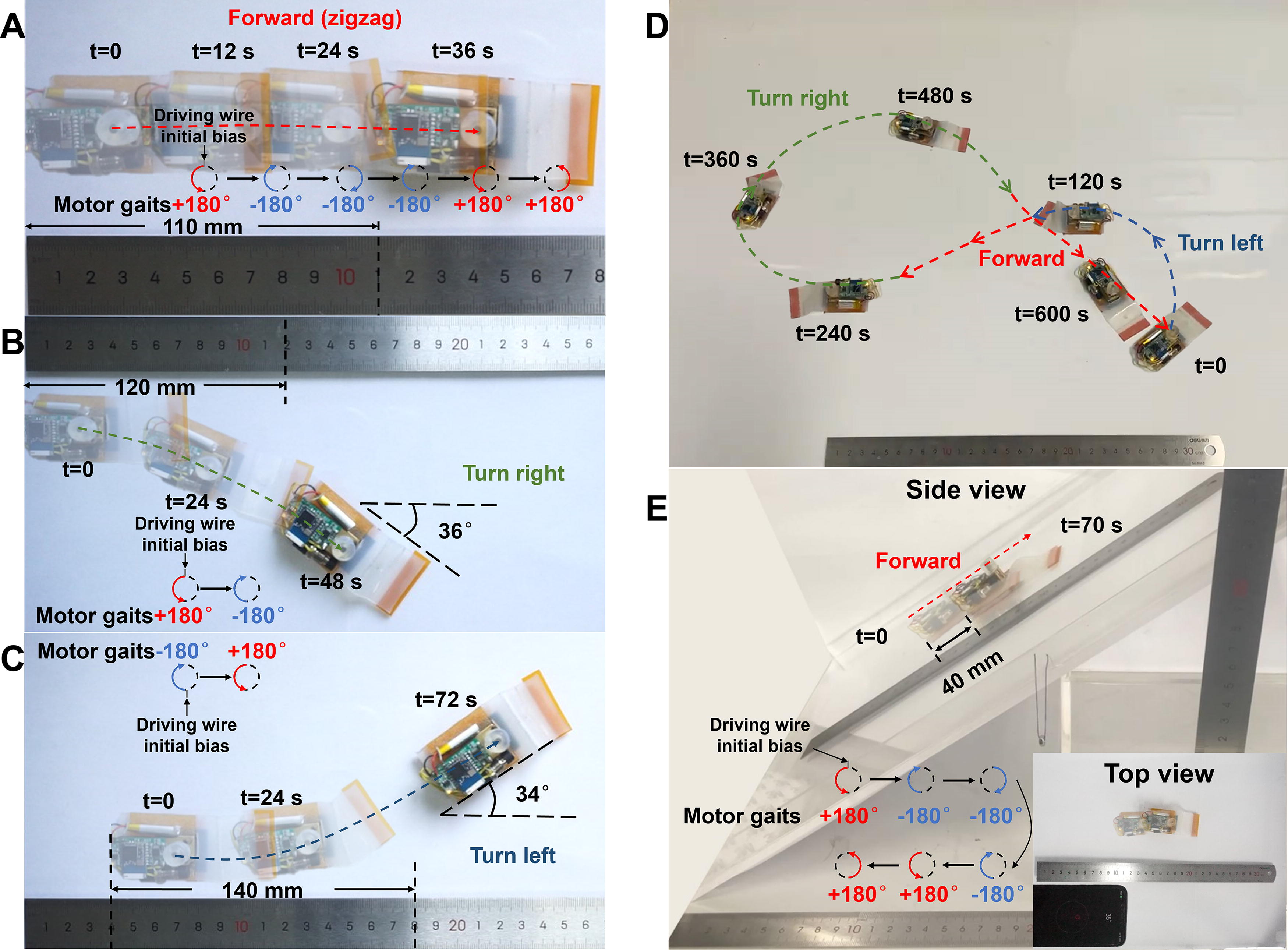
Land crawling performance of the robot on acrylic substrate.
Moreover, due to the high adhesiveness of the silicone material and the anisotropic friction mechanism of the robot, the robot also possesses a certain degree of climbing ability.37,38 For instance, Figure 6E shows the robot climbing a 35° slope, covering 40 mm in 70 s at a reduced speed of 0.57 mm/s. During climbing, the importance of the front pad with crevices is further emphasized, as robots without creases are unable to climb even a 16° slope (Supplementary Movie S1).
Load capacity and rough surface adaptability
Soft robots often need to carry various cargos, such as sensors, actuators, and monitoring devices, to function in complex environments. Thus, the load capacity is indicative of their range of detection and perception. We conducted tests on the payload-carrying capacity of this soft robot. For these tests, weights were placed steadily on top of the control board (Fig. 7A), and all payload tests were carried out using the same experimental setup to ensure the validity and accuracy of the data. The robot crawling speed under different loads was tested using the average speed over 10 cm distance for each test. As the load increased, the crawling speed decreased (Fig. 7B). The robot was tested with a maximum effective payload of 204 g, demonstrating its ability to smoothly execute turning ability (zigzag locomotion) with a load eight times its own weight (Fig. 7A and Supplementary Movie S2). The robot’s ability to steer with such significant weights is primarily due to the powerful driving force of the motor and the folding mechanism of the origami silicone pad, as well as the powerful anisotropic friction mechanism on the load capacity. 39 Additionally, the anisotropic friction mechanism of the robot can also exhibit strong adaptations in different environments,40,41 as shown in Figure 7C. The robot can crawl through (i) pipelines, (ii) plastic mesh, (iii) lawns, and (iv) uneven ground (Supplementary Movie S2). The robot’s silicone pads may collect dust and particles over time, leading to significant slippage during crawling and further decreasing performance. To prevent contamination, the robot’s pads should be cleaned regularly.

Robot load capacity and adaptability to other terrestrial environments.
Here, we summarize and compare our robot with other motor-driven soft crawling robots, as shown in Table 1. Our robot has a significantly lower body mass (26.5 g) compared with others, which makes it lightweight and easy to maneuver. The length of our robot (7.5 cm) is shorter than others listed in Table 1, and its compact size contributes to the unique set of functionalities. While our robot may not excel in speed, it offers a balanced performance with its small mass, compact size, and high-load capacity. Specifically, its ability to accomplish forward and steering motions with a single actuator sets it apart, providing an efficient and practical solution for applications requiring lightweight and versatile crawling robots.
Comparison of Our Robot with Other Motor-Driven Soft Crawling Robots
Different actuation methods bring unique benefits and challenges. For instance, magnetic actuation enables robots to be lightweight and agile, but controlling the magnetic field is difficult to integrate, limiting these robots to a fixed operating range.43,44 Pneumatic actuation offers high output power and fast response but faces challenges to miniaturize.45,46 SMA actuation is easy to control; however, it is less energy-efficient and performs lower than motor-driven systems.18,47 LCE actuators are highly flexible, capable of strong deformation, and responsive to various stimuli such as light, heat, and electricity, thus showing strong environmental adaptability. 48 However, LCEs still need improvement in durability and efficiency. Although dielectric elastomer actuators have a fast response time and large deformation, they rely on extremely high driving voltages, making it difficult to achieve integration and miniaturization. 14 These comparisons underscore the practicality of our motor-driven robot, which strikes an effective balance between simplicity, flexibility, functionality, and load-carrying ability.
Swimming performance
We have also tested the robot’s ability to move in aquatic environments. By attaching a piece of foam under the robot sufficient to support its buoyancy, it can perform controlled gliding movements on the water surface (Supplementary Movie S2). As shown in Figure 8A, the gliding cycle of the robot on the water surface is 3 s, involving one counterclockwise and clockwise rotation of the motor. When the motor tightens the silicone pad, the robot’s front end sinks deeper due to its forward center of gravity, increasing the forward resistance (Fig. 8Ai) and preventing the forward gliding (Fig. 8Aii). Conversely, the rear end of the setup sinks less in-depth, offering less resistance to backward movement. When the motor reverses and releases the silicone pad, its elastic backward slap on the water propels the robot backward for a certain distance (Fig. 8Aiii). Similarly, as the motor rotates in different directions, the deformation shape of the silicone changes, altering the direction of the force exerted by the silicone on the water (Fig. 8Bi). Additionally, as demonstrated in Figure 8Ci and ii, the robot’s direction of gliding on the water is controllable. However, due to the asymmetry of the robot and factors such as water surface waves, the turns are not symmetrically balanced. The electrical data in one driving cycle (∼3 s) of crawling on land substrate and gliding on water surface are measured in Figure 8D and E, respectively. For the locomotion of land crawling, the input electrical power from the battery is estimated as 210 mW, and the output electrical power from the motor is estimated as 86 mW. For water gliding, the input electrical power is 200 mW, and the output electrical power is 82 mW. The power consumption of land crawling is a little bit higher than that of water gliding due to larger resistance on land.

The untethered locomotion of the robot gliding on the water surface.
Conclusions
This article introduces a single-motor-driven soft robot that mimics the turning motion of snails. The robot uses the anisotropic friction to facilitate its crawling movement, and the origami bending of the silicone pad significantly enhances its crawling performance. For single-actuator drive, controlling the difference in the extension speeds of the left and right sides of the robot to achieve steering is simple and efficient. It effectively avoids the performance degradation caused by multiple actuators and transmission structures. This is a method that has never been used in soft robots before and is expected to see expanded application in the future. The soft robot integrates a control system for real-time trajectory management. Although there are already many soft robots capable of steerable independent crawling, their body structures are often too flexible, or their driving forces are too weak to handle large loads, which limits their potential application. In this work, we have made several key advancements: (i) Using only one motor, the robot can perform flexible crawling movements, including forward crawling with the speed of 3 mm/s, active steering at radius speed of 0.75°/s, and climbing slopes of 35°; (ii) this untethered motor-driven soft crawling robot is simple in design, only 7.6 cm long and weighing 26 g, making it as one of the smallest of its kind in motor-driven soft crawling robots; (iii) the robot can stably carry a load of 204 g (nearly eight times its own weight), representing the strong load capacity among untethered soft crawling robots of this scale; (iv) the robot is capable of adapting to various environments for crawling, such as through pipelines, plastic mesh, lawns, and uneven ground surfaces; and (v) the robot’s motion modes also can be applied directly to water surface gliding scenario and the robot can also well achieve active steering in this situation, fitting the needs of amphibious applications.
A centimeter-scale untethered amphibious soft snail robot capable of large loading capacity holds significant value in narrow environments. This robot design provides a novel method to develop controllable single-motor-driven soft robots. However, as some parts of the robot are still rigid, achieving full softness in motor-driven robots remains a challenge. Future research may involve increasing the crawling speed, extending working conditions, improving the robustness of the robot system, and implementing communications platform for potential swarm behavior of multiple snail robots.
Footnotes
Author Disclosure Statement
The authors declare no competing interests. Y.W. conceived the idea, analyzed the data, and wrote the article. L.C. designed the robot, carried out the experiments, and developed the theoretical model. G.L. designed the circuits. B.P., Q.L, and Y.S. assisted the fabrication and revised the article. Y.W. and S.G. supervised the project.
Funding Information
This work is supported by the National Natural Science Foundation of China under grants 52005083 and 62103291, Sichuan Provincial Science and Technology Department under grants 2024NSFSC0144 and 2023YFG0057, Guangdong Basic and Applied Basic Research Foundation 2022A1515011063, and the Fundamental Research Funds for the Central Universities ZYGX2021YGLH221.
