




Abstract
Small-scale soft robots, despite their potential for adaptability in unknown environments, often encounter performance constraints due to inherent limitations within soft actuators and compact bodies. To address this problem, we proposed a fast-moving soft robot driven by electroactive materials. The robot combines the advantages of dielectric elastomer actuators (DEAs) and shape memory alloy (SMA) spring actuators, enabling its high-performance multi-modal locomotion in a small and lightweight design. Theoretical models were constructed for both DEAs and SMA spring actuators to analyze the performance of the designed robot. The robot’s design parameters were optimized based on these models to improve its running and jumping performance. The designed robot has a size of 40 × 45 × 25 mm and a weight of 3.5 g. The robot can achieve a running speed of 91 mm/s, ascend a 9° slope, and execute turning motions via an asymmetrical actuation of SMA spring actuators. The robot also demonstrates high-performance jumping motions with a maximum jumping height of 80 mm and the ability to jump over a 40 mm high obstacle. This work introduces a novel approach to designing small-scale soft terrestrial robots, enhancing their agility and mobility in obstacle-laden environments.
Introduction
Small-scale soft terrestrial robots (1 mm < body length < 100 mm) have become one of the most popular research topics in the robotics community. These robots utilize the soft actuators to achieve performance comparable with that of rigid robots, while also allowing for more flexible body designs in limited size scales. This makes them particularly suitable for locomotion tasks inside constrained unstructured environments such as search-and-rescue,1–3 pipe inspection,4–6 and medical treatment.7–10 Among these robots, terrestrial robots are most widely studied because of their low energy consumption, simpler designs, and wide application scenarios.
In the past decade, different designs were utilized to enable small-scale soft robots with better terrestrial locomotion capabilities, including legged locomotion modes11–13 and whole-body locomotion modes.14,15 Actuator performance is one of the key factors in deciding the robot’s locomotion capabilities (speed, terrain adaptability, etc.). To improve the locomotion performance of the robots, different actuation technologies were applied to drive the robots, such as pneumatic actuation, 16 magnetic field actuation, 17 and electrical actuation using dielectric materials18,19 or piezoelectric materials. 20 Despite all the progress, the robot’s size and the actuators’ energy output are still the main limitations of these robots’ performance. Meanwhile, small-scale robots also have difficulties navigating through obstacle-laden environments. Different designs have addressed the problem to enable the robot’s jumping21,22 or wall-climbing motion.23–25 However, the specific design of the actuation mechanisms, such as a latch-release mechanism for jumping robots or an attach-detach mechanism for wall-climbing robots, make these robots limited to a specific locomotion mode and less adaptable to the change of terrains.
Nature is one of the most important sources of inspiration for robot designs. Almost all animals can switch between different locomotion modes to adapt to changing environments. Many researchers have been learning from nature to enable multi-modal locomotion capability in small-scale soft robots. Some existing designs utilize the high output force of soft actuators to achieve crawling and jumping motion in small-scale robots.19,26–28 However, these designs did not fully unleash the capabilities of soft actuators in each locomotion mode. Their designs use the same actuator for different locomotion modes, making compromises during the design. One way to improve the performance of multi-modal locomotion of robots is to combine different actuators together, each responsible for the specific locomotion mode. This design methodology has been proven successful in some robots29,30 with larger size scales (>100 mm). However, this method is difficult to apply to small-scale robots due to their size and weight limitations. How to realize multi-modal locomotion without hugely impacting the performance of small-scale robots remains an open research problem.
To address the aforementioned problems, this work designed a small-scale soft terrestrial robot utilizing the high-frequency actuation dielectric elastomer actuators (DEAs) and high energy storage of shape memory alloy (SMA) spring actuators. Both actuators are designed to be compact and lightweight, allowing better performance for running on flat terrain and jumping over obstacles. To achieve the optimal design parameter, analytical models are proposed for the actuators used in the robot, and their design parameters are optimized. Experiments are carried out to show the effectiveness of the proposed design methodology.
Robot Design and Locomotion Strategies
The overall design of the robot is illustrated in Figure 1a. The robot is mainly constructed in two parts. The first part is the bistable structure at the front of the robot, which is made of several units with two SMA spring actuators and one polyimide (PI) elastic plate in the middle. The second part is the DEA-driven joint made of PI elastic frames and a pre-stretched dielectric elastomer (DE) membrane. The SMA bistable structures and the DEA-driven joint will bend in the unactuated state, forming the robot’s front and hind legs. Fasteners connect the two parts. A soft foot pad is added at the bottom of the hind leg to increase friction with the ground.

Overall design and locomotion strategies of the proposed robot.
The robot can realize a fast-running gait by actuating the DEA with high-voltage signals. When the voltage is turned on, the instant actuation of DEA will send the robot into a leaping motion, as shown in Figure 1b. The voltage will be turned off during the leaping phase, and the hind leg is contracted. Finally, the robot finishes one running step by landing on the ground and preparing for the next gait cycle. The robot’s turning motion is explained in Figure 1c with the example of the left-turning motion. By actuating the left SMA spring actuator on the upper side and the right one on the bottom side, the front part of the robot will be twisted, and the left side of the hindfoot will be lifted. In this state, the friction force generated by the soft pad is biased to the right side, generating a left-turning momentum. Right turning can also be achieved by actuating the SMA spring actuators in symmetric positions.
In the presence of obstacles, the robot can switch to the jumping motion with the help of energy storage and release of SMA bistable structures, as illustrated in Figure 1d. The robot will first get into a preparation pose by actuating all the SMA spring actuators on the upper side. Afterward, the SMA spring actuators on the upper side will be turned off, and those on the bottom will be turned on. In this process, the bistable structure will slowly bend downwards. The structure will then undergo a snap-through process, instantly releasing the elastic energy stored in the actuated SMA spring actuators and sending the robot into the air. The jumping angle can be controlled with the help of DEA. By actuating the DEA, the contact angle between the hindfoot and the ground can be adjusted, which changes the direction of the jumping force applied to the robot during the jumping motion.
Analytical Modeling
Dynamic modeling of the DEA-driven joint
Gent constitutive model is used to describe the hyperelastic property of the DEA. The strain energy density is a function of three principal stretches (λ x , λ y , λ z ). The DE membrane forms a saddle shape in the designed structure. This geometric nonlinearity makes it hard to explicitly describe the strain distribution across the membrane at the state of large deformation. Therefore, a simplified method is used in this work to construct the model.
The geometric model used for the proposed design is illustrated in Figure 2. The octagon-shaped DE membrane is divided into nine sections. Assuming the principal strains are the same for every point inside each section, the stretch distribution on the membrane can be described by the design parameters of DEA shown in Figure 2a and the deformation variables of the elastic frame and DE membrane as shown in Figure 2b. For the three sections in the middle row along the x-axis (sections 4, 5, and 6) and y-axis (sections 2, 5, and 8), its strain along x- and y-axis can be calculated from the length of arc Cx and Cy formed by these sections (the red dashed line in Figure 2b) respectively as

Modeling of the DEA-driven joint.
For other sections, the corresponding strains in x- and y-direction are assumed to be the average of each point’s strains in each section. The strain on the edges connected with middle sections is the same as the values calculated in Equations (1) and (2), and the strain on the edges connected with the outer frame remains constant as the pre-stretch value λ
x,pre
and λ
y,pre
. By integrating each point’s strain over each section, we get
The stretch in the z-direction can be computed as λ z,i = 1∕(λ x,i λ y,i ) in incompressive materials.
A dissipative model based on the Gent model is used for the modeling of the visco-hyperelastic property of the DE membrane.
31
This model describes the material as a system of nonlinear springs and dashpots in x- and y-directions as illustrated in Figure 2c. The strain density function of the model can be written as
Euler-Lagrangian equation of motion is used for the dynamic modeling of the DEA-driven joint. The Euler-Lagrangian formulation of a nonconservative system can be written as
By choosing q = [h, θ, ξx,1,ξy,1,…,ξx,9,ξy,9] ∈ ℝ
20
, the total strain energy of the system can be written as
The electrical strain energy density function induced by Maxwell strain can be expressed as
Here, E = Φ/t denotes the electric field across the DE membrane, where Φ is the electrical potential difference between two sides of the membrane, and t is the pre-deformation thickness of the membrane. Consequently, the total electric potential energy can be formulated as
The charging and discharging time of the capacitor is neglected in the model, as the DEA’s capacitance is around 100 pF and the resistance of the flexible electrodes is around 100 kΩ, which leads to a resistor-capacitor time constant of around 10 μs. This value is much smaller than the actuation speed of the mechanical system (around 100 ms).
By considering one end of the DEA-driven joint being fixed, the kinetic energy of the system equals the kinetic energy of one side of the elastic frame rotating around the joint’s hinge with angular velocity
For the dissipation function, the energy dissipation inside DE (DVE) can be calculated using the Rayleigh dissipation function
The energy dissipation in the rotating joint (Dframe) can be approximated using the term α as following:
Energy-based modeling of the SMA bistable structure
An energy-based model is built for the SMA bistable structure to predict its quasistatic deformation and jumping performance. The two-state model 32 is used to model SMAs. This model considers only the full martensite state at low temperatures and the full austenite state at high temperatures. The force-displacement curve of SMA springs described by the two-state model is shown in Figure 3a. This relationship can be seen as linear when the SMA is in a full austenite state with small shear strains (<1%).
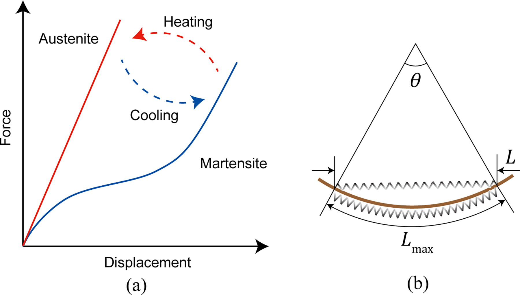
Modeling of the SMA bistable structure.
The elastic strain energy of SMA spring actuators on both sides is
Model-Based Design Optimization
Design optimization of the DEA-driven joint
The visco-hyperelastic parameters for the 3M VHB elastomer are determined using the stretching test result from Ref. 33 The particle swarm algorithm is used from the MATLAB toolbox (R2022b, MathWorks Inc.) to search for the best-fit parameters. The fitted curves are plotted in Figure 4d.

Model verification and design optimization of the DEA-driven joint.
The experimental results of the quasistatic response with DC voltages from 1 to 4 kV are shown in Figure 4a. The finite element method (FEM)-based results are shown in Figure 4b, where the constitutive model of DEA is described using user-defined materials (UMAT) 34 in Abaqus 2021 (Dassault Systèmes Simulia Corp.). The results based on the analytical model in Equation (5) are calculated using fmincon in MATLAB by letting the time derivatives of all the generalized coordinates be zero. The voltage-angle relationships at different pre-stretch ratios from the analytical model and FEM are compared in Figure 4c. These results show that the analytical model can fit the nonlinear response of DEA at different conditions, with the error of the bending angle less than 0.23 rad for all the points under 5 kV. The computation time of the voltage-angle relationship for each pre-stretch condition using the analytical model is 36 s on a desktop (with Intel Core i7 14700 CPU, 32GB RAM). Meanwhile, getting the same result costs 21 min using FEM on the same computer, which is 35 times slower. Therefore, the analytical model provides a much faster design optimization process.
The unknown frictional parameter α in Equation (12) is fitted with the experimental data by actuating the DEA-driven joint with 3 kV square wave signals at frequencies between 2 and 20 Hz. The fitted result is plotted in Figure 4e.
Using the fitted dynamic model, the robot’s running speed is optimized using two objective functions. The first is the total weight of the robot fobj1 = mDE + mSMA, where mSMA is estimated as 1.5 g. The second is the opposite of the maximum output speed of the joint, which is calculated as
The optimization uses the multi-objective genetic algorithm in MATLAB. The Pareto front during the optimization is plotted in Figure 4f. The five best individuals are selected from the last generation, and their parameters are listed in Table 1. Among these individuals, D is selected to be the parameters used for the final version of the robot. Although E has a higher locomotion speed, its weight is also much higher, which will reduce the achievable jumping height.
Best Individuals from Gen 100 of MOGA Optimization
MOGA, multi-objective genetic algorithm.
Design optimization of the SMA bistable structure
The energy-based model of the SMA bistable structure describes the maximum possible jumping height of the robot. The robot’s jumping height is proportional to N-times of the energy barrier ΔUtotal of the bistable structure (as shown in Figure 5a) divided by the total mass Mt of the robot, where N is the number of bistable units in the structure. The mass of the DEA-driven joint is estimated to be 3 g. The optimization variables are selected as wBF and L as shown in Figure 5b, because these parameters significantly influence the energy barrier of the bistable structure and can be easily modified in the fabrication process. The optimization problem can be described as

Design parameter optimization of SMA bistable structure.
The optimization problem is solved by carrying out a grid search of wBF and L.
Locomotion Capability Test
Robot fabrication
The robot with optimized design parameters was fabricated using the process depicted in Figure 6a. PI films with thicknesses of 0.2 and 0.4 mm were laser cut for the elastic frame and the robot fixture, respectively. Two layers of dielectric films with a thickness of 1 mm (3M VHB 4910) were pre-stretched by 4 × 4, and electrodes made by multi-walled carbon nanotubes (MWCNTs, Suzhou Tanfeng Graphene Technology Co., Ltd.) were brushed on both sides through a masking layer. Afterward, two layers were stacked together and stuck to a PI elastic frame and fixtures after removing the masking layer. The SMA springs (Shenzhen Superline Technology Co., Ltd.) with a wire diameter of 0.3 mm, a coil diameter of 3 mm, and a natural length of 12 mm were fixed with nylon bolts and nuts through pre-cut holes on PI frames. Nylon bolts were used to avoid electric connections between different SMA springs. The foot structure at the hind leg was made by a 0.4 mm PI plate and bounded to the end of the DEA-driven joint along with a 1 mm thick silicone-made friction pad using double-sided tapes. The total weight of the assembled robot is 3.5 g.

Fabrication process and experimental setup.
Experimental setup
The electronic peripherals were designed to control the high-voltage signal for DEAs and the DC currents for SMA spring actuators. A 10 kV DC-DC amplifier (UltraVolt 10A12-P4, Advanced Energy) was used to supply the high voltage. A custom-built optocoupler circuit based on the design of Mitchell et al. 35 was built to achieve high-speed control of DEAs.
The currents in the SMA springs were controlled by MOSFET (IRFR024N, International Rectifier) arrays with pulse-width modulated signals. Hall-effect-based current sensors (ACS712, Allegro Microsystems) provided feedback on actual currents.
All the actuation circuits were connected to a single Cortex-M3-based microcontroller (STMicroelectronics). Locomotion data of the robot was captured using a high-speed camera (iPhone XR, Apple Inc.) at 240 fps and analyzed with Tracker software. The schematic of experiments is illustrated in Figure 6b.
Running motion test
The robot’s forward-running motion on a PVC surface is shown in Figure 7a. The square wave signal with frequencies between 2 and 20 Hz was used to control the optocouplers, where the voltage of the DC amplifier was set to 5 kV. The relationship between the control frequency and the robot’s speed is plotted in Figure 7b. The robot achieved the maximum running speed of 91 mm/s at 12 Hz, which was 2.02 times the body length per second (BL/s).

Experimental results of the robot’s running motion.
The robot’s turning ability was tested under the same setting, with SMA spring actuators selectively actuated with 500 mA current based on the desired turning direction as described in Section “Robot Design and Locomotion Strategies.” Results of the robot carrying out left and right turning motions are shown in Figure 7d. After carrying out five repeated tests in each direction, the average turning radius (Rturn) achieved by the robot was measured as 208 mm, which was 4.6 times the body length of the robot.
The forward-running motion test was repeated on other materials, including glass, printing paper, steel, and wood, to show the robot’s adaptability on different terrains. These materials covered a wide range of different surface roughness and hardness. Figure 7c shows the maximum speeds achieved on these surfaces. The robot achieved higher maximum speeds on PVC and wood, while the speeds on the glass and steel were significantly lower. This was due to the lower surface friction between the silicone pad and the glass or steel surface. The slope climbing test was also carried out on a PVC surface with slope angles of 5°, 9°, and 15°. The robot was able to ascend on the slope of 5° at an average speed of 52 mm/s, and on the slope of 9° at an average speed of 30 mm/s (Figure 7e). It failed to ascend the slope of 15°.
The robot’s load-carrying ability is also tested to show its future possibility to fully carry the weight of its power source and control board. The robot is loaded with metal payloads weighing 5 g, as shown in Figure 7c. Running speeds were tested under each condition. The result shows that the robot could run under 5 and 10 g loads, with an average speed of 58 and 34 mm/s, respectively. This shows the robot’s good potential for future untethered operation.
Jumping motion test
The SMA control signals used in the jumping motion test with their corresponding temperature changes are illustrated in Figure 8a. During the test, the SMA springs were actuated using DC currents of 800 mA. A certain time delay was given between the upper and bottom springs’ actuation. Changing the length of the time delay can adjust the amount of released energy during jumping.

Testing of the robot’s jumping motion.
Different time delay values were tested in the vertical jumping motion. The robot reached a maximum jumping height of 80 mm with a time delay setting of 2 s. This jumping performance is compared with that of the standalone SMA bistable structure to show the influence of adding the DEA structure on the robot’s jumping performance as shown in Figure 8b. The SMA bistable structure alone reached the maximum jumping height of 96 mm. This height is slightly higher than that of the designed robot, considering the lighter weight of the SMA bistable structure (2.3 g).
The jumping height and forward distance can be controlled by applying different voltages on the DEA. This changes the contact angle of the hind foot with the ground, affecting the friction force generated during jumping. Figure 8c illustrates the measured jumping trajectories. The average jumping height with VDEA = 0, 2.5, and 5 kV are 78, 69, and 60 mm, respectively. The corresponding jumping distances are 14, 31, and 49 mm. The robot’s obstacle-crossing capability was shown with the DEA actuated at 5 kV over an obstacle with a height of 40 mm as shown in Figure 8d. In some experiments, the robot landed upside down because of the rotational momentum generated during the jumping motion. The control of landing pose is out of the scope of this research. Nevertheless, the robot’s pose can be flipped back by repeating the jumping motion.
Adding payloads will reduce the robot’s jumping height. This influence was tested with 5 and 10 g payloads added to the robot. With a 5 g payload, the robot could vertically jump to a height of 52 mm and jump across a 25 mm obstacle as shown in Figure 8e. However, the robot could not carry out significant jumping motion when the payload weight was increased to 10 g.
Energy cost analysis
The energy consumption associated with the robot’s various modes of motion is essential for enabling untethered locomotion, particularly when operating with a limited power supply. The energy cost of the SMA spring actuators can be calculated by measuring electrical currents Ik(t) flowing through k-th SMA spring in real-time. The resistance of each SMA spring is estimated to be constant R. The power cost of the SMA springs is then presented as
For straight-line running motion, only DEA is actuated. At maximum running speed, the average energy cost of a 10 s period was measured to be around 1.5 mJ. By dividing the total energy by the product of mass and traveled distance, the corresponding cost of transport (CoT) is calculated as 7.69 J/(kg·m). The energy cost of the jumping motion was calculated from the energy used by all SMA springs during one jumping cycle as shown in Figure 8a. The average energy used in one jumping cycle was around 90.08 J. These results show the significant advantage of having DEA in the robot, which has a much lower energy cost.
Sensing ability demonstration
To show the robot’s sensing ability, a 60% humidity indicator was pasted on the back of the robot, as shown in Figure 9. The robot carried the indicator inside the target area, and the change of color on the indicator successfully showed the rise of the humidity in the air. Other possible sensors to be carried on the robot include light, chemical, and temperature sensors. Some lightweight inertial measurement units are also available within the robot’s load-carrying capability, which will give the robot the ability to navigate intelligently in complex environments.

Demonstration of the robot’s sensing ability. The robot carries a humidity indicator to detect the change in environmental humidity.
Conclusion
This article designed a small-scale soft robot with high-performance multi-modal locomotion capability. The robot utilized the advantage of the large deformation and energy storage capability of SMA spring actuators and the high-frequency output of DEAs to achieve better performance in running, turning, and jumping motions. The theoretical model of the robot was constructed using an energy-based model for the SMA bistable structures and a visco-hyperelastic model for the DEA-driven joint. A geometrical simplification was made to calculate the strain distribution in the DE membrane under nonlinear deformation, which improved the calculation speed by 35 times while preserving accuracies for quasistatic and dynamic analysis. Based on these models, the robot’s performance in running and jumping motion was optimized. The optimized design of the robot achieved a maximum running speed of 91 mm/s (2.02 BL/s), a maximum jumping height of 80 mm (1.78 BL), and an obstacle-crossing height of 40 mm. The robot could also carry out turning motions with an average turning radius of 208 mm (4.6 BL) and ascend a slope of 9° at 30 mm/s speed. The performance of the designed robot is compared with other related works as listed in Table 2. Most works with multi-modal locomotion capabilities use single actuation methods, therefore are only optimally designed for one locomotion mode. This work combines the strength of different actuators in a small and lightweight design, achieving performance comparable with other small-scale robots in both running and jumping locomotion modes. This overall performance makes the robot more suitable for exploration in complex terrains with obstacles while still capable of high-speed locomotion with low CoT.
Comparison of Robot’s Performance with Related Works
BL, body length; DEA, dielectric elastomer actuator; SMA, shape memory alloy.
One of the limitations of the current robot design is the need for tethers for power supply and control. In the future, it is possible to make this robot fully untethered by lowering the DEA’s actuation voltage and properly designing a powering and control circuit. Also, this work’s theoretical model did not consider the robot’s interaction with the ground. Although the methods used in this work provide enough accuracy for the design optimization, a more accurate dynamic model can give the robot more adaptive locomotion strategies on different terrains to further improve its performance.
Footnotes

References
Supplementary Material
Please find the following supplemental material available below.
For Open Access articles published under a Creative Commons License, all supplemental material carries the same license as the article it is associated with.
For non-Open Access articles published, all supplemental material carries a non-exclusive license, and permission requests for re-use of supplemental material or any part of supplemental material shall be sent directly to the copyright owner as specified in the copyright notice associated with the article.
