




Abstract
Robotic links play a vital role in transmitting force and torque, ensuring precise robotic movements. Traditional rigid links, typically made from metals, pose a risk of injury in human–robot interactions or damage to other objects due to their noncompliant and stiff nature and have limited adaptability across various tasks. Variable stiffness robotic links (VSRLs) using hydraulically amplified self-healing electrostatic (HASEL) actuators offer a solution, enhancing safety and adaptability while maintaining precision. This study introduces an electrohydraulic jammed VSRL utilizing a strip-shaped HASEL actuator, which stiffens upon application of high-voltage, pressurizing dielectric liquid encased in a dielectric bladder to achieve stiffness variations up to 8.3 times. The VSRL, optimized by adjusting liquid volume and sealing patterns, is lightweight and compact and eliminates the need for bulky pumps and motors. It also functions as a capacitor, enabling a self-sensing strategy to detect deformation. Experimental results demonstrate significant stiffness variability and effective load-bearing capabilities. Multi-VSRL assemblies further enhance stiffness for practical applications, including collaborative robotic links and wearable robots for joint support. A unique drone application showcases the VSRL’s potential for energy-efficient aerial operations. The proposed VSRL represents a promising advancement in robotic technology, offering improved safety, adaptability, and functionality for diverse real-world applications.
Introduction
Robotic links are crucial elements of robots in transmitting force and torque, facilitating precise movements.1,2 They empower robots to handle payloads and execute manipulation tasks accurately. Nevertheless, traditional robotic links are typically crafted from rigid materials such as metals, preserving a fixed shape and high stiffness after manufacturing.3–5 This trait renders the robot susceptible to damage upon collision with the environment.6,7 Moreover, during physical human–robot interaction, there is a heightened risk of human injury in the case of accidental collisions with these rigid robotic links.8–10 This disadvantage is particularly pronounced in wearable robots that operate closely to the human body, where rigid links with fixed shape not only diminish comfort but could impede the flexibility of human joints.11–13 In addition, links with a fixed shape limit the robot’s ability to reconfigure and adapt to different tasks.14–16
To tackle these challenges, recent research has delved into the utilization of variable stiffness robotic links (VSRLs) to enhance intrinsic safety and shape adaptability in robots, while still maintaining relatively high manipulation accuracy. The ability to adjust stiffness and shape in robotic links enables them to accommodate a variety of tasks. Stiffened VSRLs excel in achieving precise movement, whereas soft VSRLs allow the robot to passively adapt to external forces and deformations, protecting both the robot and its users. VSRLs are primarily achieved through mechanisms such as jamming and antagonism.17,18 For instance, a tubular jamming robotic beam was proposed in ref. 19 , where multiple pneumatic fabric tubular actuators are enclosed in an inextensible tubular sleeve. By applying pneumatic pressure to these actuators, the friction between them increases, significantly enhancing the overall stiffness of the tubular beam. Layer jamming and granular jamming are also employed in VSRLs, often requiring bulky vacuum pumps.20–22 In these cases, a vacuum is applied to layers or granules within a soft, enclosed sleeve, and external barometric pressure squeezes these layers or granules to stiffen the sleeve. Some researchers utilize antagonism between tight limiting cables driven by motors and other components to increase internal stress and stiffen the robotic links. 23 In addition, the anisotropy of materials can be leveraged for stiffness adjustment in VSRLs. For example, certain VSRLs consist of an array of stainless-steel sheets and pneumatic actuators or motors integrated to alter the shape and orientation of the steel sheets.17,24 The anisotropic stiffness of the steel sheets allows for adjustment of the total stiffness of the VSRLs. While significant efforts have been made to improve the mechanical design for achieving higher variable stiffness, the requirement for pneumatic/vacuum pumps or magnetic motors has constrained the compactness and practicality of VSRLs.
The electrohydraulic actuator, known as the hydraulically amplified self-healing electrostatic (HASEL) actuator, has garnered significant research attention due to its rapid response, high power density, and low noise levels.25–27 Applying electrostatic fields, electrohydraulic actuators generate Maxwell stress to compress a dielectric bladder filled with dielectric liquid. This compression induces a “zipping” deformation of the bladder, resulting in mechanical actuation. This technology has found widespread application across various robotic systems, including grippers,28–30 locomotion robots,31–33 and artificial muscles.34,35
In this article, we introduce an electrohydraulic jammed VSRL in the form of a strip-shaped HASEL actuator. By applying high voltage to the strip-shaped HASEL actuator, the inner dielectric liquid is jammed (i.e., pressurized), resulting in increased stiffness. Compared with other variable stiffness mechanisms, the primary advantage of our electrohydraulic jammed VSRL is its lightweight and compact design, without the need for connected pneumatic pumps and motors, yet achieving significant stiffness variation, up to 8.3 times its baseline. In addition, we optimized the variable stiffness performance of the basic VSRL design by adjusting the volume of dielectric liquid, revising the sealing pattern of the strip-shaped HASEL actuator, and incorporating multiple VSRLs. Furthermore, our VSRL functions as an intrinsic capacitor, with deformation inducing capacitance changes. Leveraging this property, we developed a self-sensing strategy to detect its deformation through detected capacitance changes of the VSRL. With these unique features, the proposed VSRL fulfills various functions, including collaborative robotic links, wearable ankle fixtures, and aerial robotic links, tailored to diverse task requirements. Our compact, self-sensing VSRL, coupled with advancements in variable stiffness performance and practical functionality, serves as a promising foundation for the development of next-generation variable stiffness mechanisms for real-world applications.
Methods
Design of electrohydraulic jammed VSRL
The design concept of the electrohydraulic jammed VSRL is a strip-shaped HASEL actuator comprising a dielectric bladder sandwiched by two flexible conductive electrodes. When applying high voltage (AC voltage as the reference 36 ) to the two electrodes, the Maxwell stress generated by the attraction of induced dissimilar charges in the two flexible conductive electrodes zips the part of the dielectric bladder covered by the electrodes. The inner dielectric liquid is pushed to the other part of the bladder without electrodes and exerts a Maxwell stress, causing the formation and pressurization of a tubular liquid chamber (see Fig. 1A, where the positive electrode is connected to the high-voltage source and the negative electrode is connected to ground), leading to increased stiffness of the overall HASEL actuator and jamming the actuator in this conformation (see Fig. 1B).

Variable stiffness principle of VSRL.
This principle provides an effective method to adjust the stiffness of the VSRL by regulating the voltage applied to the HASEL actuator. To demonstrate our design concept, we mounted both ends of the VSRL on two platforms placed 100 mm apart and hung a 20 g weight in the middle of the VSRL (see Fig. 1C and Supplementary Movie S1). Without high voltage applied to the VSRL, the weight easily caused the VSRL to bend and collapse due to the lack of stiffness. However, upon application of high voltage to the VSRL, the stiffened VSRL can easily support a 20 g weight without deformation.
Self-sensing for bending deformation
Our electrohydraulic jammed VSRL is intrinsically a capacitor, and its capacitance can alter with deformation. Since the applied voltage to the VSRL is AC square wave high voltage, we can measure the absolute value of the AC current passing through the capacitor to detect the change of the capacitance, which, in turn, indicates the deformation of the VSRL. Then, we designed a circuit by connecting a 100 kΩ resistor between one electrode of the VSRL and the ground (see Fig. 2A). A data acquisition device was used to measure the voltage of the resistor and a real-time data filter combining the sliding mean filter and the peak pulse interference filter. The passing current is linearly related with the measured voltage of the resistor. The bending deformation of the VSRL will redistribute the dielectric fluid back to the section of the VSRL covered by electrodes, separating the electrodes from their zipped state. Therefore, the capacitance will drop down due to the increased distance between the electrodes (see Fig. 2B), also resulting in a drop in the passing current. The deformation can be sensed with low latency by real-time monitoring of the filtered absolute value of the AC current. We experimentally verified the self-sensing strategy by repeatedly bending the VSRL with 3 mL dielectric liquid (see Fig. 2C and Supplementary Movie S2), and the results were consistent. The filtered signal declined with bending initially from 0.2 s to 0.4 s, and then increased with a peak from 0.55 s to 0.7 s as the VSRL was restored. Therefore, we can detect the bending deformation of the VSRL by monitoring the changes in the filtered signal.

Self-sensing for the deformation of VSRL.
Results and Discussion
Characterization of VSRL
Based on the working principle of our electrohydraulic jammed VSRLs, the stiffness of our electrohydraulic jammed VSRLs is primarily determined by the pressure and shape of the tubular liquid chamber. Therefore, the volume of the dielectric liquid, coupled with the applied voltage, significantly influences the stiffness of the VSRLs (see Fig. 3A). To characterize the variable stiffness of our electrohydraulic jammed VSRL, we designed a testing platform to measure the bending moment applied to the VSRL. A load cell was mounted on a ball-screw slider (1.25 mm/s speed), with a press head connected to the load cell. The VSRL was fixed facing the press head, and on the opposite side, a laser sensor was used to measure the moving distance. As the slider moved toward the VSRL, the press head bent the VSRL. Simultaneously, the load cell measured the contacting force, and the laser sensor measured the bending displacement (see Fig. 3B). The press head was pressing the middle of the VSRL and the fixture is 27 mm wide (see Fig. 3C), so the bending moment can be calculated by multiplying the measured force and the moment arm (33 mm).

Characterization of the stiffness of VSRL.
We varied the volume of dielectric liquid in the VSRLs from 2 mL to 7 mL and applied different high voltages ranging from 0 V to 6 kV. The experimental pressing forces with the pressing displacements are depicted in Figure 3D. A 5 mm gap was maintained between the press head and the tested VSRLs, ensuring that all pressing forces gradually increased from the 5 mm displacement. First, the volume of dielectric liquid significantly influenced the stiffness of the VSRLs. For instance, the VSRL with 3 mL dielectric liquid exhibited a maximum pressing force of up to 11 gf (107.8 mN), whereas the VSRL with 2 mL dielectric liquid achieved a maximum pressing force of less than 6 gf. The minimal stiffness of the VSRL was approximately 0.133 gf/mm when the voltage was 0 V (as indicated by the black dots in the 2 mL subfigure of Fig. 3D). For the liquid volumes of 3 mL, 5 mL, and 7 mL, the significant weight of the liquid makes it challenging for the VSRL at 0 V to maintain a stable testing configuration, as shown in Figure 3B. This is due to the gravitational force causing considerable twisting of the VSRL at low displacements. Therefore, we use the stiffness value of 0.133 gf/mm, measured for the VSRL with 2 mL of liquid, as the baseline stiffness. Furthermore, the stiffness marginally increased with the applied voltage from 4 kV to 6 kV for VSRLs with 2 mL, 3 mL, and 5 mL dielectric liquid. All pressing forces increased with displacement initially and then decreased. This phenomenon occurred because the tubular shape of the jammed liquid was disrupted due to the large bending angle of the VSRLs with 2 mL, 3 mL, and 5 mL dielectric liquid. However, for the 7 mL liquid, the VSRL became too heavy, causing it to hang down with a significant bending angle due to gravity, resulting in a rapid decline in pressing force (see Fig. 3D).
The VSRL with 3 mL of dielectric liquid demonstrated the highest stiffness, reaching up to 1.1 gf/mm with a 6 kV voltage, achieving the maximum range of variable stiffness. The stiffness of the VSRL exhibited a substantial variation, rising from a baseline of 0.133 gf/mm at 0 V to a peak of 1.1 gf/mm at 6 kV with 3 mL of dielectric liquid. This 8.3-fold increase highlights the exceptional tunability of the proposed design, demonstrating its potential for adaptable performance in various applications. In contrast, when the volume of dielectric liquid was only 2 mL, the jammed tubular dielectric liquid chamber was not fully filled, resulting in relatively low pressure within the chamber and, consequently, lower stiffness of the VSRL. However, VSRLs with more dielectric liquid (5 mL and 7 mL) also exhibited reduced maximum stiffness. This was primarily due to the jammed liquid chambers not maintaining an ideal tubular shape. The volume of the dielectric liquid exceeded the maximum capacity of the chamber without the carbon ink electrode covering, causing incomplete and uneven zipping of the electrode area and causing much of the dielectric liquid to be pushed toward the middle or other side of the chamber (refer to Fig. 3E for 5 mL and 7 mL liquid). Hence, the dielectric liquid in the bending section was insufficient to effectively stiffen the VSRL (see the section view in Fig. 3E).
Optimization of VSRL
To address the issue of uneven zipping of electrodes, we introduced a hump of PVC double-sided adhesive tape to the middle area of the VSRL, forming a two-segment VSRL (see Fig. 4A). This modification helps refine the orientation of the zipping spread. Previously, without the middle hump of PVC double-sided adhesive tape, the electrodes would zip from both sides toward the middle or from one side to the other, causing the dielectric liquid to gather in the middle or on one side of the VSRL, as depicted in Figure 3E. However, with the addition of the middle double-sided adhesive tape, the electrodes now zip from the middle to both sides (see Fig. 4C and Supplementary Movie S3), resulting in more dielectric liquid being pushed into the ideal tubular liquid chamber. After conducting the same testing as in Figure 3, we observed that the maximum pressing forces of the two-segment VSRL with 5 mL and 7 mL dielectric liquid were enhanced by 18.3% and 10.7%, respectively, compared with the initial one-segment VSRLs (see Fig. 4B). However, for the VSRL with 3 mL of liquid, the maximum stiffness remained almost constant. This is because all of the 3 mL liquid can be accommodated into the chamber without electrode covering, and it cannot influence the electrode zipping. In both the initial and revised VSRLs, the 3 mL liquid was pushed out into the tubular chamber. Although the optimized polyvinyl chloride (PVC) -adhesive pattern (two-segment VSRL) enhances the maximum pressing force of VSRLs with 5 mL and 7 mL liquids, the highest pressing force is achieved by the VSRL with 3 mL of dielectric liquid using the original one-segment PVC-adhesive pattern. Therefore, this design was selected for subsequent experiments and applications.

Optimization of the stiffness of VSRL.
Considering the cross-section size of the stiffened VSRL, we designed a dual cross-folded VSRL to achieve higher stiffness (see Fig. 4D) by sticking two cross-folded VSRLs (one-segment VSRL with 3 mL dielectric liquid) together. The dual cross-folded VSRL maintains the same size as a single VSRL during the stiffening state (see Fig. 4D, the length L, thickness t, and width W of the single VSRL and the dual cross-folded VSRL are same). The tested pressing force with displacement and the maximum pressing force with 0 V, 4 kV, 5 kV, and 6 kV are illustrated in Figure 4E and F. Ideally, the dual cross-folded VSRL should achieve double the pressing force of a single VSRL. However, it falls short of reaching double the maximum force of a single VSRL, even though it is significantly higher than the single VSRL. In Figure 4E, we also tested the pressing force under a 7 kV voltage. The results showed that the stiffness of the dual cross-folded VSRL remained nearly constant when the voltage exceeded 5 kV, consistent with the stiffness trend observed in a single VSRL at voltages above 5 kV (see Fig. 3D).
We also conducted hysteresis tests by pressing the VSRL over long distances (from 5 mm to 30 mm) and short distances (from 5 mm to 10 mm). In the forward long-distance test, we observed an obvious elastic region at about 10 mm from the start point, in which the force increased linearly with the pressing displacement to 11 gf (see Fig. 4G). After the elastic region, a yield point was reached, and the force gradually declined to 3 gf. In the backward long-distance test, the force remained almost constant as the pressing displacement decreased, then abruptly rose to 6 gf once the pressing displacement returned to the elastic region. Subsequently, the force dropped to 0 gf as the displacement continued to decrease. In the short-distance test, the pressing force increased linearly with the displacement, indicating that the bending angle of the VSRL remained within the elastic region throughout the test.
Multi-VSRLs for robotic applications
A single electrohydraulic jammed VSRL has relatively limited stiffness and load capacity, and its own weight reduces the available payload. For real-world robotic applications, we combined multiple VSRLs into a robotic link to achieve higher stiffness (see Fig. 5A). We designed a circular fixture that can mount six electrohydraulic jammed VSRLs at 60-degree intervals around a central shaft (6-VSRL). We tested the bending stiffness of the 6-VSRL configuration by horizontally pulling a hook connected to a load cell to measure the pulling force (see Fig. 5A). The hook was attached to the lower central shaft of the vertically mounted 6-VSRL assembly, with a distance of 145 mm from the hook to the upper fixture (see Fig. 5A). We controlled the applied AC square wave voltage, alternating between 6 kV and 0 V and tested the bending stiffness in two orientations (see Fig. 5B). In the first pulling orientation, the hook was positioned at the middle between two VSRLs, while in the second orientation, the hook was aligned with a single VSRL (see the cross-section schematic in Fig. 5B). With 0 V applied (see the black line in Fig. 5B), the pulling force in the first orientation increased with the displacement from 0 to 40 gf, then gradually declined to 30 gf after exceeding the yield point at 13 mm. However, with 6 kV applied (see the red line in Fig. 5B), the yield point was delayed to 20 mm, and the pulling force rose to 70 gf at the yield point without a significant drop afterward. For the second pulling orientation, the pulling forces followed similar trends as in the first orientation, but the force difference between the 6 kV and 0 V conditions was minor, less than 10 gf. This variation is due to the inconsistent bending stiffness of a single VSRL in different orientations (more than 10 times stiffness variation in the longitudinal orientation and only 2 times in the lateral orientation) (see Supplementary Data).

Multi-VSRLs for robotic applications.
To demonstrate the variable stiffness of the 6-VSRL assembly, the upper end of the assembly was connected to a servo motor with the rest of the assembly hanging downward, after which the assembly was rotated 90 degrees with the servo motor to a horizontal cantilever position. This was done with and without a 20 g weight attached to the lower end of the assembly, and with and without application of high voltage to the VSRLs. Without high voltage applied, the 6-VSRL exhibited low stiffness and could not support its own weight, causing it to hang down when rotated to a horizontal cantilever position (see Fig. 5C and Supplementary Movie S4). The deflection angle of the 6-VSRL with 0 V applied was significantly higher compared with when 6 kV was applied. Furthermore, we developed a 3-DoF robot configured with three servo motors for shoulder rotation, shoulder extension/flexion, and elbow extension/flexion, along with two multi-VSRL robotic links for the arm and forearm, designed for object delivery (see Fig. 5D). Considering the uneven moment distribution on the arm and forearm, the arm was equipped with a 6-VSRL assembly, while the forearm was equipped with a 3-VSRL assembly, where only three electrohydraulic jammed VSRLs were mounted in the fixture at 120-degree intervals. With the stiffened VSRLs, the robot could support its own weight and successfully deliver a 20 g object to the target position (see the footage in Fig. 5D and Supplementary Movie S4). For safe human–robot interaction, the robot can be softened simply by removing the applied high voltage.
To highlight the potential of our electrohydraulic jammed VSRL for wearable robots, we designed a soft variable stiffness ankle exosuit for sprain protection (see Fig. 5E). Ankle sprains typically occur due to an accidental large inversion–eversion angle of the ankle joint. Thus, we utilized dual cross-folded VSRLs that, when active, can stiffen to restrict the inversion–eversion motion of the ankle, and when inactive, can transition to a soft and compliant nonstiffened state to accommodate the ankle’s normal motion. First, we created a mock-up of a human ankle joint using a universal joint, 3D-printed shank and foot, and a children’s shoe. We then mounted two dual cross-folded VSRLs as an exosuit on both sides of the mock-up ankle using four fixtures. These VSRLs were attached to two fixtures on both sides of the foot with double-sided adhesive tapes, while the other two fixtures were fixed on the shank (see the bottom-left schematic in Fig. 5E). The VSRLs were inserted into the fixtures on the shank without double-sided adhesive tapes, allowing the deactivated VSRLs to slide freely through the fixtures and bend to adapt to the inversion–eversion motion of the ankle (see Fig. 5E and F and Supplementary Movie S5). When the VSRLs are activated, they become stiff and act as rigid exoskeletons, restricting ankle motion to prevent sprains (see Supplementary Movie S5). To prevent electric shock, we designated the inner electrodes of the dual cross-folded VSRLs as the high-voltage electrodes (see Fig. 4D), ensuring that these high-voltage electrodes are enclosed by insulators, protecting the human body from exposure. Our experiment illustrated that the VSRL exosuit could effectively jam the mock-up ankle joint when high voltage was applied, providing rigidity and protection. In addition, the exosuit could switch to a free state, allowing for normal ankle motion when the voltage was removed.
Multimodal VSRL-drone landing and taking off from a tree branch
When drones perform intermittent aerial operations such as aerial photography and long-term environmental monitoring, traditional drones typically need to take off and land from ground bases, which requires significant energy to overcome gravitational potential energy. Given the widespread presence of trees on Earth, we envisioned a scenario where drones could land on, park, and take off from tree branches to conserve energy. Inspired by the way soft clothes hang on drying racks, we innovatively proposed a multimodal VSRL drone capable of landing and taking off from a tree branch. Our soft electrohydraulic VSRL can stably hang on slender branches like clothes, while the stiffened VSRL can transmit force to achieve controlled flying postures.
We developed a simplified drone with two motors connected by a dual cross-folded VSRL. The propellers on the motors are configured as forward and reverse propellers to reduce spinning torque, and all power for the motors and the VSRL is supplied off-board (see Fig. 6A). The motors are mounted on fixtures to which the VSRL is attached using double-sided adhesive tapes. For landing on a tree branch, the drone with a soft VSRL can buffer the impact of the landing kinetic energy and deform to stably hang on the branch (parking on a tree branch, see Fig. 6B and C). In contrast, a stiffened VSRL would remain straight and struggle to balance on the branch, likely resulting in a fall (see Fig. 6C). We verified the feasibility of landing on a branch by releasing the drone from a certain height above the branch. As the drone descended rapidly, the experiment results (see Fig. 6D and Supplementary Movie S6) demonstrated that the soft VSRL could passively bend and hang onto the branch upon landing. This self-adaptive landing on a branch also absorbs the landing kinetic energy. Therefore, it allows for a relatively higher landing velocity compared with the conventional slow-landing mode, which enhances maneuverability. Conversely, with the stiffened VSRL, the drone could not balance on the branch upon landing due to the landing kinetic energy and subsequently falls off the branch (see Fig. 6E).
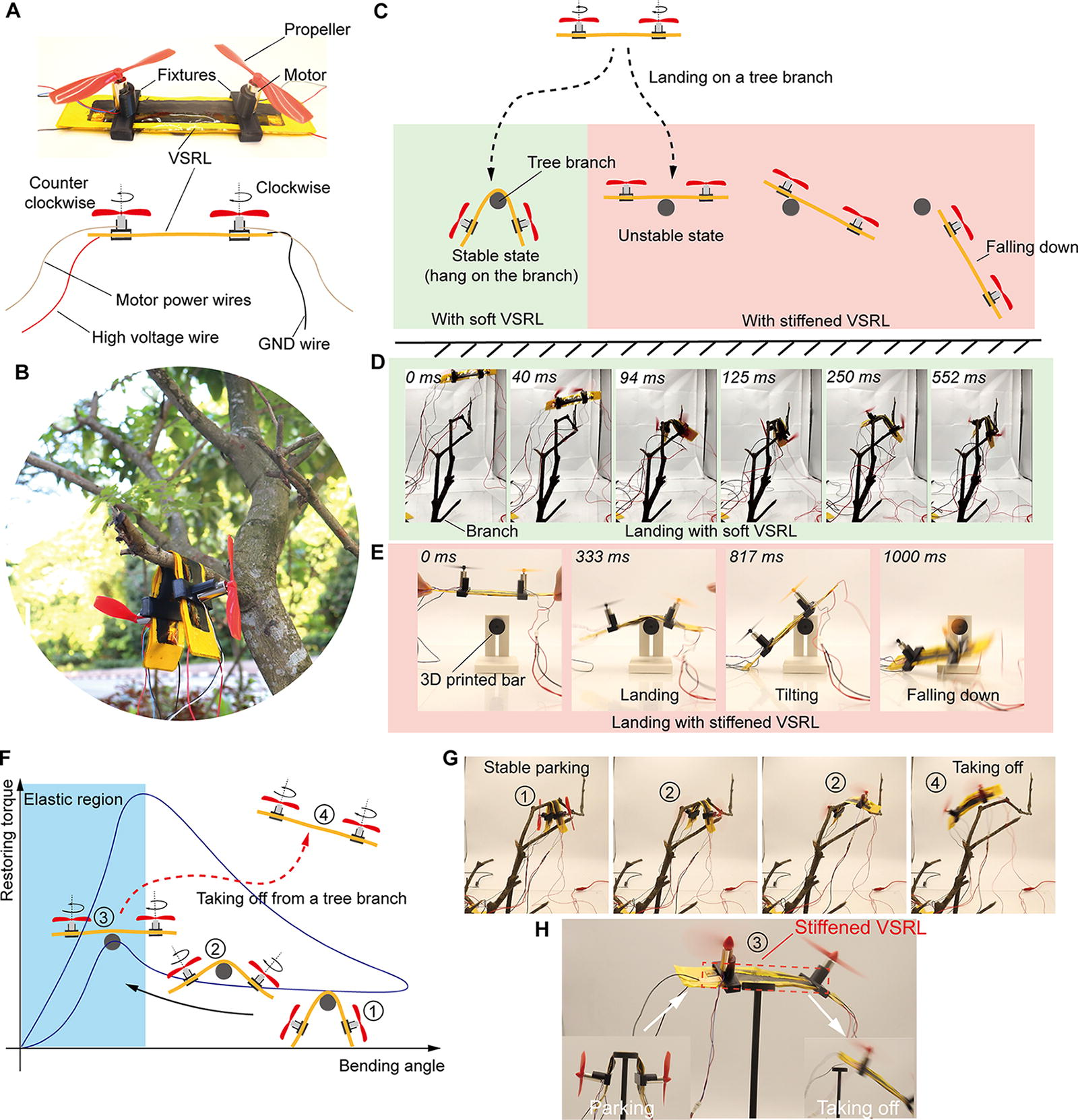
VSRL-drone landing and taking off from a tree branch.
To facilitate takeoff from the branch, we first applied a 6 kV voltage to the VSRL and then powered on the motors to provide lift force. Initially, the drone stably hangs on the branch with the VSRL at a large bending angle. Applying high voltage to the VSRL, the restoring force-angle curve deduced from the long-stroke hysteresis test in Figure 4G illustrates that the restoring force of the VSRL is insufficient when the bending angle is large (① in Fig. 6F), causing the VSRL to maintain its large bending angle. As the lift force from the motors’ propellers increases, it begins to dominate the restoring process of the VSRL, causing the bending angle to gradually decrease (② in Fig. 6F). Once the bending angle drops into the elastic region, the restoring force of the VSRL abruptly rises due to the electrohydraulic jamming mechanism, and the VSRL promptly becomes stiffened and straight (③ in Fig. 6F). By continuing to increase the motors’ rotating speed, the drone is able to take off from the branch (④ in Fig. 6F). The experimental footage of the drone taking off from a branch (see Fig. 6G and Supplementary Movie S6) generally supported our analysis, although the transient state ③ was not visually observed. To address this, we replaced the tree branch with a flat surface to help balance the drone during the transient state ③. This setup allowed us to clearly observe state ③, characterized by the tubular chamber of liquid (see Fig. 6H and Supplementary Movie S6).
Conclusion
In this study, we introduce VSRLs utilizing electrohydraulic jamming principles. These links, based on HASEL actuators, consist of a dielectric bladder and flexible electrodes that, when subjected to high voltage, form a pressurized tubular liquid chamber to increase stiffness. The stiffness of VSRLs can be dynamically controlled by varying the applied voltage, with rapid switching between soft and stiff states that are similar to the characteristics of HASEL actuators. We propose a cost-effective fabrication method using polyimide films, known for their high permittivity and mechanical strength, and PVC double-sided adhesive tapes. Then, we optimize VSRL performance by adjusting the dielectric liquid volume, refining the sealing pattern of the HASEL actuator, and integrating multiple VSRLs. The optimized dual cross-folded VSRL achieves higher stiffness within the same dimensions as the original design, enhancing its potential for space-limited applications such as wearable robotics. In addition, VSRLs function as intrinsic capacitors, where deformation causes changes in capacitance, enabling a self-sensing strategy for real-time deformation detection. This self-sensing capability allows VSRL-based robots to self-monitor their states and respond quickly. Demonstrated applications include a 3-DoF robot for handling objects with variable stiffness for safe human–robot interaction, a soft ankle exosuit for sprain protection, and a drone capable of landing and taking off from tree branches, showcasing the versatility and potential of VSRLs in robotics.
The limitations and future work of this work are as follows. First, we currently utilize a heavy off-board amplifier that limits the portability, and we will develop a miniaturized high-voltage supply for convenient practical use. Second, we will continue improving the maximum attainable stiffness by selecting new dielectric materials and optimizing the design. Third, based on the self-sensing strategy, an intelligent algorithm to measure the actual bending angle of the VSRL will be developed by using machine learning.
Footnotes
Acknowledgment
The authors acknowledge the assistance of the Department of Mechanical Engineering, National University of Singapore.
Authors’ Contributions
Q.X. conceived the idea, designed the experiments, conducted the main experimental work, and wrote the manuscript. X.Z. and D.L. assisted with the experimental implementation. G.T. contributed to data analysis and assisted in manuscript preparation. D.R. provided critical revision and feedback on the manuscript. R.C.-H.Y. contributed to the conceptualization and secured funding for the project. All authors reviewed and approved the final manuscript.
Author Disclosure Statement
No competing financial interests exist.
Funding Information
This work was supported by National Robotics Programme—Robotics Enabling Capabilities and Technologies (W2025d0243) and A*STAR Industry Alignment Fund—Pre-Positioning (A20H8A0241).
