
Abstract
Abstract
Recent advances in commercial space transportation emphasize rocket engine reusability, reduced number of stages, and its operation over a wide range of operating conditions. The rocket nozzles typically underperform at sea level where they operate at highly overexpanded pressures. This leads to flow separation inside the nozzle that lowers nozzle efficiency. In addition, asymmetric flow separation inside the nozzle will generate side loadings and large amplitude pressure fluctuations resulting in nozzle fatigue and a catastrophic mission failure. The main objective of this study is to characterize the performance of a scaled convergent–divergent supersonic rocket nozzle by identifying flow separation locations along the diverging section at various nozzle operating conditions. This information was then used to guide the implementation of active flow control technique using transverse secondary gas injection microjets near the separation line. Measurements include pressure distributions inside the nozzle with and without microjet control over a range of nozzle pressure ratios (NPRs) and velocity field measurements in the jet plume near the nozzle exit. Results show that the flow separation location is a function of the NPR for the baseline configuration. An increase in NPR results in a delay in the flow separation marked by a downstream movement of separation location. Microjet control appears to be very effective in delaying the flow separation, increase the jet diameter at the exit plane, and thereby improve the stability of the jet plume.
Introduction
The purpose of a rocket nozzle is to accelerate the high-pressure high-temperature combustion products to produce thrust as a high-momentum jet. The nozzle is an important component of a rocket because its efficiency significantly affects the overall performance of the rocket. By optimal design of nozzle contour and by attenuating the various losses (shown in Fig. 1) in the nozzle, the thrust of the rocket can be boosted, which, in turn, will increase its range and payload capacity. Optimum thrust can be acquired by the total expansion of the exhaust gases to the surrounding ambient pressure through a nozzle designed to generate a parallel uniform flow at the exit. A perfectly expanded nozzle has no flow separation and maximizes nozzle efficiency. Rocket nozzles are underexpanded when the exit static pressure is higher than the ambient pressure and overexpanded when the exit pressure is lower than the ambient pressure. Rocket nozzles typically operate overexpanded during launch and at low altitudes. In overexpanded cases, rocket nozzles face a number of issues affecting their performance and efficiency. The pressures associated with shock impingement and flow separation fluctuate at high frequencies and large amplitudes that generate material fatigue due to cyclic stresses on the nozzle and supporting structure. Any asymmetry in the flow separation (and shock impingement) leads to (unintended) side loading that vectors the thrust away from the axial direction. Flow separation additionally creates areas of no flow and flow entrainment within the boundary layer reducing thrust.
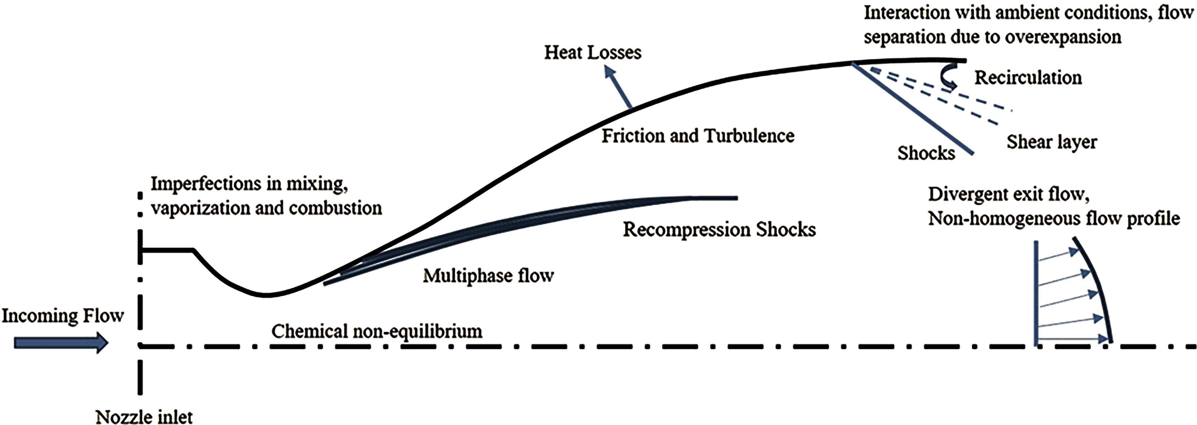
Schematic of flow phenomena and sources of losses in rocket nozzles. Color images are available online.
The commercial space industry has recently been shifting toward reusable designs, using parallel stage configurations over tandem stage designs. 1 Parallel stage rockets have the main booster that fires for a majority of the flight, necessitating operation over a large range of conditions. The concept of single-stage-to-orbit (SSTO) transport vehicles with reusable engines has been halted by technological challenges including nozzle inefficiency outside of the design range. 2 Consequently, a nozzle with the capability to prevent flow separation in overexpanded cases is of particular interest. Sources Rao 3 and Hagemann et al. 4 indicate an “altitude-compensation nozzle” would be a technology needed for the realization of SSTO. Specifically, Hagemann et al. 4 discuss “reduction of side-loads during sea level or low-altitude operation” as a principal concept for improving the standard bell rocket nozzle. They suggest that altitude adaptive rocket nozzles would facilitate the design of reusable rockets and the use of stages over a wider range of operating conditions.
The phenomenon of flow separation and generation of side loads has been widely investigated by various researchers.1,5–8 Hunter 5 attributed the reason for flow asymmetry as the natural tendency of an overexpanded nozzle flow to detach and reach a more efficient thermodynamic balance and instead, not because of markedly different start-up conditions or stronger shock wave boundary layer interaction. Östlund and Muhammad-Klingmann 6 relate asymmetric separation to the formation of 2 different shock patterns namely free shock separation, in which the flow separates from the nozzle wall and never reattaches, and restricted shock separation, which is characterized by a closed recirculation bubble and flow reattachment on the nozzle wall, as shown in Figure 2. It is also reported that the transition between these 2 shock patterns is one of the major sources for side load generation. Side loads are an undesirable phenomenon that may not only put the mission in jeopardy but also threaten the integrity of engine and rocket components. Therefore, it is important to better understand the cause of side load generation and develop flow control strategies to mitigate asymmetric side loads.
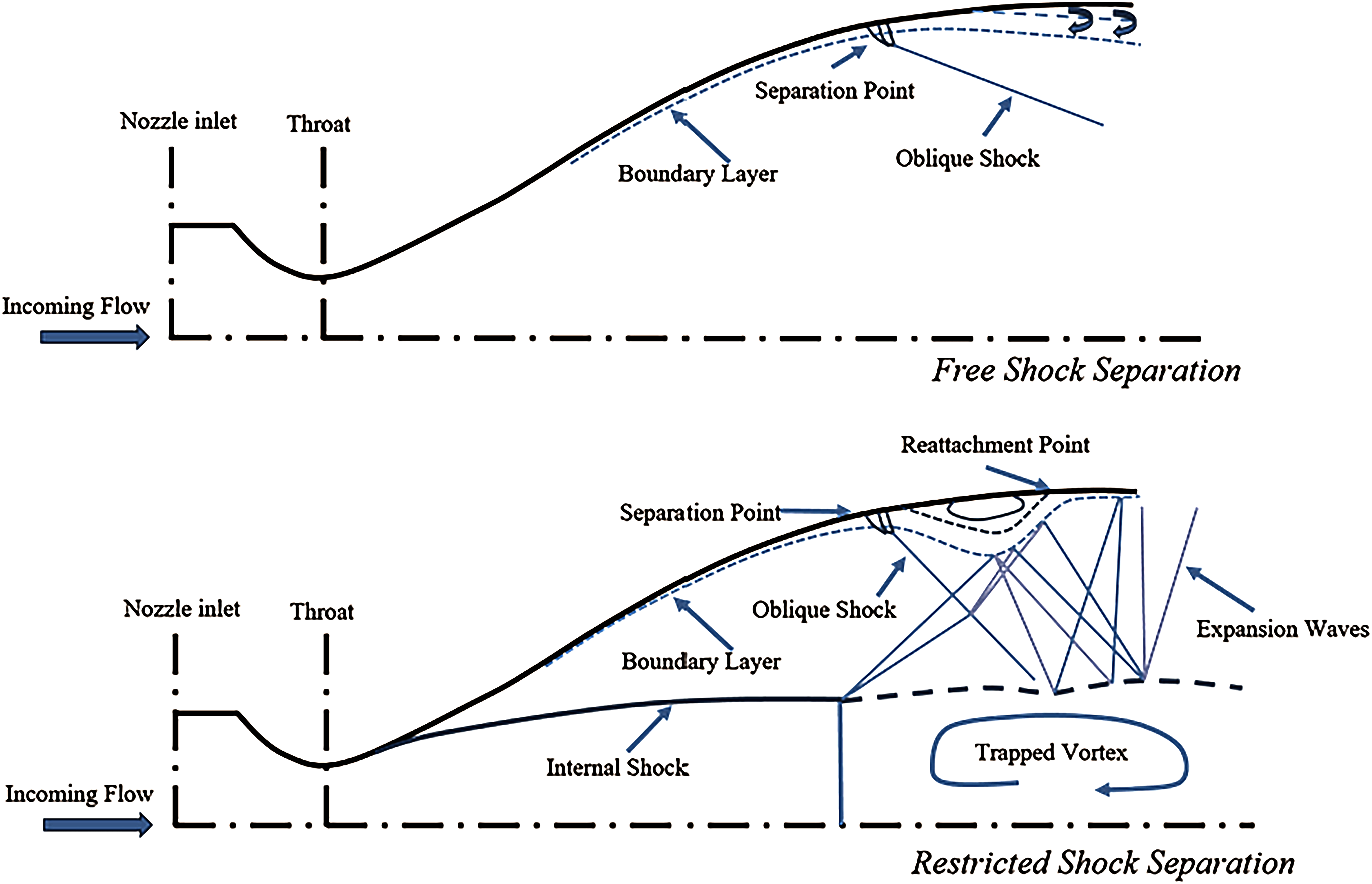
Illustration of the free shock separation and the restricted shock separation. 6 Color images are available online.
Baseline Nozzle Flow
This study concerns an overexpanded nozzle with turbulent flow separation. The nozzle is designed for optimal performance in conditions wherein the ambient pressure is much less than the atmospheric pressure of the laboratory. The nozzle shape is modeled after an ideal contour using the method of characteristics (MOC). The nozzle has a design Mach number of 4.0, an area ratio (Ae/A*) of 10.74, and an ideal nozzle pressure ratio (NPR) of 151.8 at γ = 1.4. At the design conditions, the nozzle is optimized to perfectly expand the gases to the ambient conditions with no flow separation. This research examines the nozzle performance at highly overexpanded conditions, NPR 4.0–7.5, where flow separation is evident. The thrust of the baseline nozzle was measured directly using a load cell as well as calculated using measurements from particle image velocimetry (PIV) and pitot-static probe pressure measurements. 9 In addition, the PIV measurements mapped the nozzle exhaust flow field demonstrating symmetry of the nozzle exhaust flow even at these highly overexpanded separated conditions.
This study continues the examination of the Mach 4 nozzle and characterizes the flow separation within the nozzle using surface pressure taps. The pressure distributions inside the nozzle will allude to the internal flow structure and help identify the flow separation location marked by a sudden rise in static pressure. Prior work suggests that increasing the NPR is likely to delay the flow separation.10–12 Morrisette and Goldberg 13 suggest with evidence from other studies that the separation pressure ratio (SPR), or the ratio of static wall pressure at the separation location to ambient pressure, is not a significant function of gas temperature. Although the nozzle geometries between this study and that of Morrisette and Goldberg 13 are somewhat different, linear versus the MOC, the area ratios, and consequently the design Mach numbers of the 2 nozzles are comparable. Thus, it can be expected that the temperature ratio (TR) of the jet may not significantly affect the SPR.
Microjet-Controlled Nozzle Flow
In addition, the objective of this study is to determine the effectiveness of active flow control using high-momentum microjets in delaying flow separation and improving the efficiency of nozzle flow. Unlike actuators or piezoelectric synthetic jets, microjets affect the flow with a positive net mass flow, transversely injected into the nozzle flow from the wall. Transverse microjet injection into the divergent section of a nozzle can produce 2 different effects depending on the applied microjet flow. At high mass flow rates, the microjets will induce separation near the injection location. This can be considered as a fluidic implementation of a dual-bell nozzle as discussed by Hagemann et al. 4 This can improve efficiency under some conditions and can also improve stability and axisymmetry of the separation. In contrast, injecting low mass flow rate microjets produce jets that bend downstream in the main flow, generating a pair of counter-rotating vortices from each microjet.14,15 These vortices will bring higher momentum flow closer to the wall, which has been found to delay separation in many applications.16,17 In this study, the effectiveness of microjet control will be investigated in terms of both delay in separation and improvement in the flow axisymmetry in the nozzle.
Experimental Apparatus and Procedure
Test Facility and Operating Conditions
The experiments for this study were carried out in the high-speed jet facility located at Florida Center for Advanced Aero-Propulsion (FCAAP) at the Florida State University. This is a blow down facility where the jets are exhausting horizontally to simplify the experimental setup to study both free jet and impinging jet flow physics. With the 2 stagnation chambers, fed from independently controlled pressure supply lines, the facility's capabilities are conducive for investigation of twin nozzle configurations, co-flow, and the interaction of cold fan and hot engine short take-off and vertical landing aircraft streams. The room housing this jet facility is sufficiently large (5.5 × 7.3 × 9 m) to accommodate for proper mixing and jet development. The compressed air is supplied through storage tanks with a capacity of 110 m 3 at a pressure of 3,450 kPa. This high-pressure air from the storage tanks is regulated to the desired stagnation chamber pressure and temperature using a Leslie® control valve and an inline Sylvania® 192 kW electric heater, respectively. Flow from the stagnation chamber is conditioned through a honeycomb flow straightener and a pair of wire meshes before it enters the nozzle.
In this study, an axisymmetric converging–diverging (C-D) nozzle with an area ratio of 10.72 is used. This area ratio of C-D nozzle, defined as the ratio between the area of exit to that of the throat, corresponds to a design Mach number of 4. The convergent section of the nozzle is designed using a fifth order polynomial, whereas the contour of the divergent section is designed using the MOC that produces uniform/parallel exit flow. The overall length of the nozzle is 273.05 mm with an inlet diameter of 57.15 mm, throat diameter of 12.7 mm, and an exit diameter of 41.65 mm. The nozzle was fabricated using stainless steel with high-precision machining to obtain a smooth surface finish.
The facility has the capability to attain maximum stagnation pressure of 0.76 MPa and stagnation temperature of ∼800 K. A schematic of the facility is shown in Figure 3. The control valve and heater allow varying the test conditions, namely NPR and TR. In this study, the rocket nozzle is mounted on the lower nozzle port to allow heated tests. The tests are conducted at TR of 1.0, 1.2, and 1.5 and NPR of 4.0, 5.0, 6.0, 7.0, and 7.5 for both the microjet-controlled and (uncontrolled) baseline jet configurations.

A photograph of the jet facility at the Florida State University. Color images are available online.
Steady State Pressure Measurements
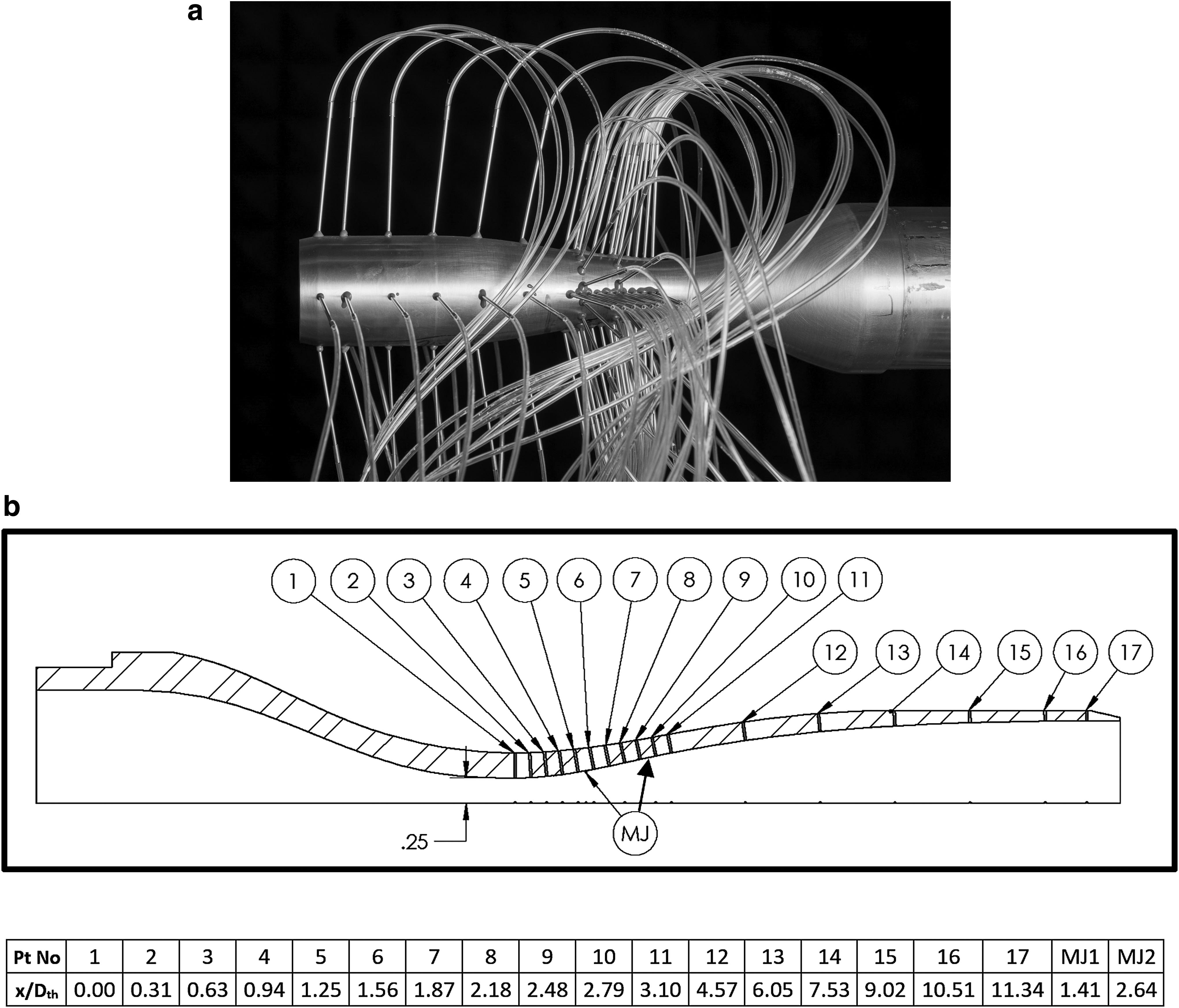
Figure 4 shows a photograph of the nozzle with pressure taps and details the nozzle geometry indicating the locations of the pressure ports and microjet arrays. The microjet diameter is 0.4 mm and the static pressure ports are 0.5 mm in diameter, respectively. The diverging section of the nozzle was instrumented with a total of 68 pressure taps at 4 azimuthal locations. The first port is located at the nozzle throat. To accurately capture the flow separation location, pressure taps were closely spaced in the zone right after the throat. Two rows of microjet arrays were inserted between existing arrays of pressure ports for flow control. The first array of microjets is located between ports 5 and 6 (x/Dth = 1.41) and the second array between ports 9 and 10 (x/Dth = 2.64), respectively. The circumferential spacing for both the sets of microjets is kept about the same (s/Dth ≈ 0.42) with 10 and 14 microjets, respectively.
The pressure ports are connected by flexible tubing to 2 Scanivalve transducer manifolds. Axial port numbers 1 through 5 (total 5 × 4 ports) are connected to an OMEGA PX315-100AI (0–100 psi range) pressure transducer through a 24-input line Scanivalve manifold JS4-24. Axial ports 6 through 17 (total 12 × 4 ports) are connected to an OMEGA PX315-030AI (0–30 psi range) pressure transducer through a 48-input line Scanivalve manifold JS4-48. Electrical signals from each transducer are measured for 1 s at the sampling rate of 1 kHz. A 2-s delay is used between ports to allow the transducer to attain a steady state at the new port location.
The nozzle static taps and microjet transducers were connected to an NI PCI-MIO-16E-1 card. The experiment LabVIEW code acquired data from the transducers while stepping the pressure scanners through the Scanivalve scanner controller. The 2 arrays of microjets are connected to 3 manifolds that are connected to the external nitrogen gas cylinder. An OMEGA PX303-200G5V (0–200 psi range) pressure transducer was connected to the microjet manifolds to measure the injection pressure. A WIKA-50398083 (0–200 psi range) pressure transducer was used to measure the stagnation chamber pressure. All the pressure transducers were calibrated before the test series. The measurement uncertainties of these sensors are within ±0.2%–0.5% of full-scale output. This corresponds to a maximum stagnation pressure measurement uncertainty of ±3.8 kPa and NPR values are accurate within ±0.0375. Surface static pressure measurements have an uncertainty of ±1.8 kPa. The uncertainty in separation location comes from the resolution of static pressure taps on the nozzle wall that is ±1.74 mm or 0.14Dth. Microjet injection pressure measurement has an uncertainty of ±3.45 kPa, which corresponds to 1% of the microjet pressure at MPR = 3.4 (0.35 MPa injection pressure), where MPR is microjet pressure ratio.
Particle Image Velocimetry
Velocity field measurements have been carried out using stereoscopic PIV for nozzle flow with and without microjets injection. Approximately 0.5 μm size glycol droplets generated by a Laskin seeder were used as a seed for the main jet. The ambient air was seeded with smoke particles (2–3 μm in diameter) produced by a Rosco® fog generator. A double-pulsed Quantel Evergreen® 200 mJ Nd:YAG laser was used to illuminate the plane of interest in the flow field. The laser beam was converted to ∼2 mm thick light sheet using the optics setup. The optics consists of a spherical lens, a cylindrical lens, and a plane mirror. LaVision DaVis 8.4 software was used for the acquisition and processing of images. The images were acquired at a rate of 7 Hz. For each case, a total of 800 image pairs were captured with a pair of 4 megapixel CCD cameras (2048 × 2048). A Scheimpflug mount with a 105 mm focal length lens was mounted on each camera. A laser intrapulse spacing of 2 μs was used based on the estimate of maximum velocity obtained from earlier experiments. 9 The processing of acquired images was done using a multipass routine starting with 64 × 64 pixels interrogation areas and decreasing interrogation window size. All passes had a 75% overlap and the final window size was 32 × 32 pixels.
Results and Discussion
Turbulent Boundary Layer
In this study, it is important to characterize the state of the boundary layer inside the nozzle. The Reynolds number for the flow in a nozzle can be defined based on the boundary layer thickness, the nozzle diameter, or the distance from the nozzle throat to name a few. Mi et al. 12 defined ReD based on the nozzle diameter along the profile and estimated a critical transition Reynolds number for the flow in a nozzle on the order of 10 5 to 10 6 . Whereas a few other studies defined Reynolds number based on the axial distance from the throat (Rex) and the range of 10 5 10 6 was classified as a “fully turbulent boundary layer.” In this study, the value of ReD is in the range of 6.9 × 10 5 to 2.3 × 10 6 and the value of ReX is in the range of 2.2 × 10 5 to 7.8 × 10 6 . Therefore, using either criterion defined in the literature, the state of the boundary layer in our experiments is turbulent along the divergent section of the nozzle.
Separation Mach Number
To compare results of various nozzle configurations operating over a range of conditions, parameters that are often used in literature18–20
are the separation Mach number (Msep, the Mach number just upstream of separation location) and SPR. There are multiple methods for calculating the separation Mach number, a variable that is difficult to measure directly. In the case of a 2-dimensional nozzle with optical access, velocity field data from PIV allow for a direct calculation in conjunction with the local temperature and associated constants:
In this study, the use of axisymmetric nozzle complicates any direct measurement of the velocity field inside the nozzle particularly close to the separation location. As a result, the separation Mach number is calculated using the isentropic relation using pressure ratios.
The stagnation pressure and temperature are measured by a transducer and a thermocouple in the stagnation chamber, respectively. The Mach numbers are determined using the stagnation chamber pressure data in conjunction with the static pressure data. Figure 5 shows a comparison plot of present data with those available in the literature. The results show a decrease in SPR with Msep, as observed in previous studies. These results indicate that the strength of separation shock is reduced and so does the pressure jump across it with an increase in separation Mach number. The SPR in this study lies within the range observed in the literature.

Separation pressure ratio as a function of Mach number (data extracted from Stark 18 ). Color images are available online.
Surface Static Pressure Distributions
As mentioned earlier, surface pressure measurements were carried out in the diverging section of the nozzle along 4 azimuthal locations. Surface static pressure distributions at NPR = 4 are shown in Figure 6. Also shown in the figure is the normalized radial location (RN/Dth) of each port along the nozzle contour. As expected, the static pressures at the throat are the maximum. The flow accelerates and becomes supersonic in the diverging section and the static pressure drops until flow separation occurs at x/Dth = 1.56. Downstream of this separation location, the flow is completely separated, the static pressure levels plateau, and then increase slightly as it reaches close to the atmospheric pressure near the nozzle exit. The pressure profiles along 4 azimuthal locations overlap, indicating an axisymmetric flow and the symmetric separation in the nozzle for this case.
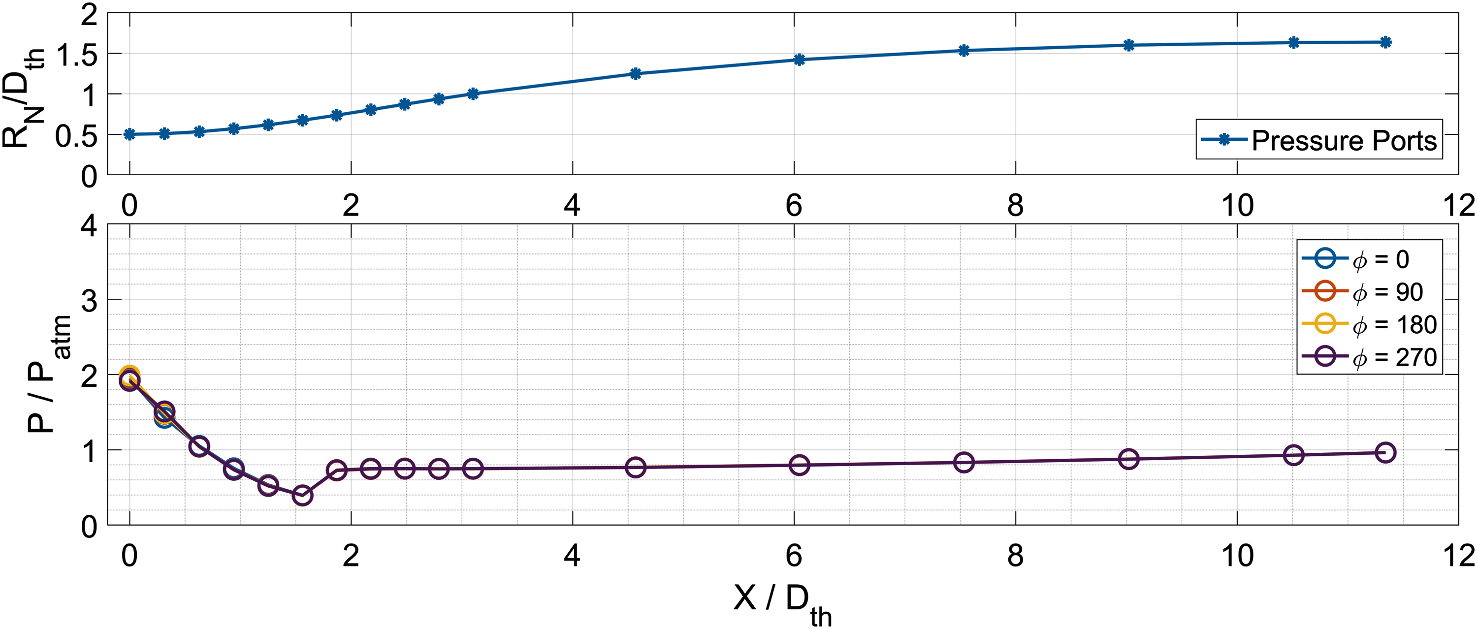
Surface static pressure distributions along the nozzle contour, NPR = 4. NPR, nozzle pressure ratio. Color images are available online.
To study the effect of temperature on flow development in the nozzle, measurements were carried out at TR = 1.0, 1.2, and 1.5. The effect of TR on surface static pressure distributions at NPR = 4 and 7 is shown in Figure 7. As seen, normalized static pressures and the flow separation locations remain unaffected by the TR at both NPRs. These results indicate that jet temperature within the range tested does not significantly affect the development of the flow inside the nozzle. Figure 8 shows the effect of NPR on static pressure distributions along the nozzle contour. In this figure, the NPR is varied from 4.0 to 7.5 and the TR is kept constant as 1.0. As seen, the normalized static pressure at the throat (x/Dth = 0) increases with an increase in NPR. The location of flow separation shifts downstream from x/Dth = 1.56 at NPR = 4.0 to x/Dth = 2.79 at NPR = 7.5, and the pressure rise across the separation shock decreases with an increase in NPR. The pressure profiles remain distinct at different NPRs farther downstream along the nozzle contour and finally merge to reach atmospheric pressure near the nozzle exit.
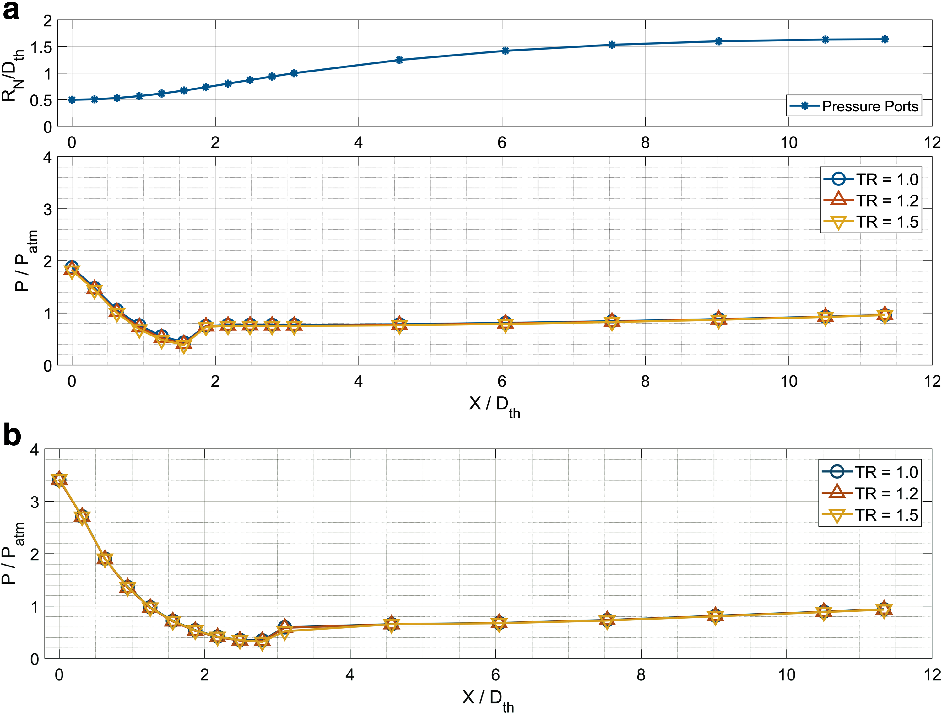
Effect of temperature ratio on the surface static pressure distributions.

Effect of NPR on the surface static pressure distributions, TR = 1. TR, temperature ratio. Color images are available online.
The effect of flow control using microjets has been investigated over a range of MPRs and NPR conditions. Figure 9 shows the effect of MPR on the pressure distributions at the 2 extreme values of NPR = 4 and 7.5, respectively. Also shown in the figure is the normalized radial location (RN/Dth) of each port along the nozzle contour, including the locations of 2 microjet arrays (MJ1 and MJ2). At NPR = 4.0, the upstream microjet array (MJ1) was activated to study the effect of MPR, as we expect this location to be the most effective. Similarly, at NPR = 7.5, the downstream microjet array was activated to investigate the effect of MPR on flow separation. The results show that all the 3 MPRs are equally effective at both NPRs. At NPR = 4.0, with microjet control, the separation location is moved downstream from x/Dth = 1.56 to 1.87 and the pressure rise is gradual as compared with a sudden jump seen for baseline flow. At NPR = 7.5, with microjet control, the separation location is moved downstream from x/Dth = 2.79 to 3.10 and, similarly to NPR = 4.0, the pressure rise is more gradual as compared with the baseline flow.
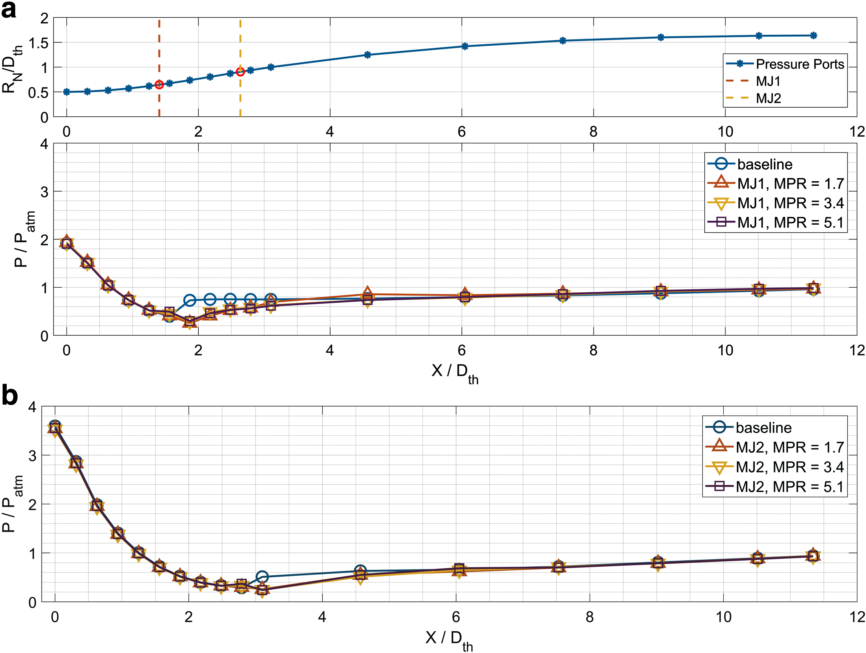
Effect of MPR on pressure distributions and flow separation location.
To further investigate the effect of microjet control and the injection location, measurements were carried out by activating MJ1 and MJ2 at each NPR and the results are shown in Figure 10. The results are shown for MPR = 3.4 and TR = 1, which are typical for all other values of MPR and TR. As expected, at NPR = 4.0, the microjet location MJ1 (at x/Dth = 1.41) is effective in delaying flow separation, whereas microjet location MJ2 (at x/Dth = 2.64) does not alter the pressure distributions. This may be due to the fact that the injection location MJ1 is slightly upstream of the flow separation location at this NPR and the streamwise vortices generated by microjets are effective in mixing the flow and delaying the separation. In contrast, injection location MJ2 is well downstream and in the separated flow region and, therefore, ineffective.
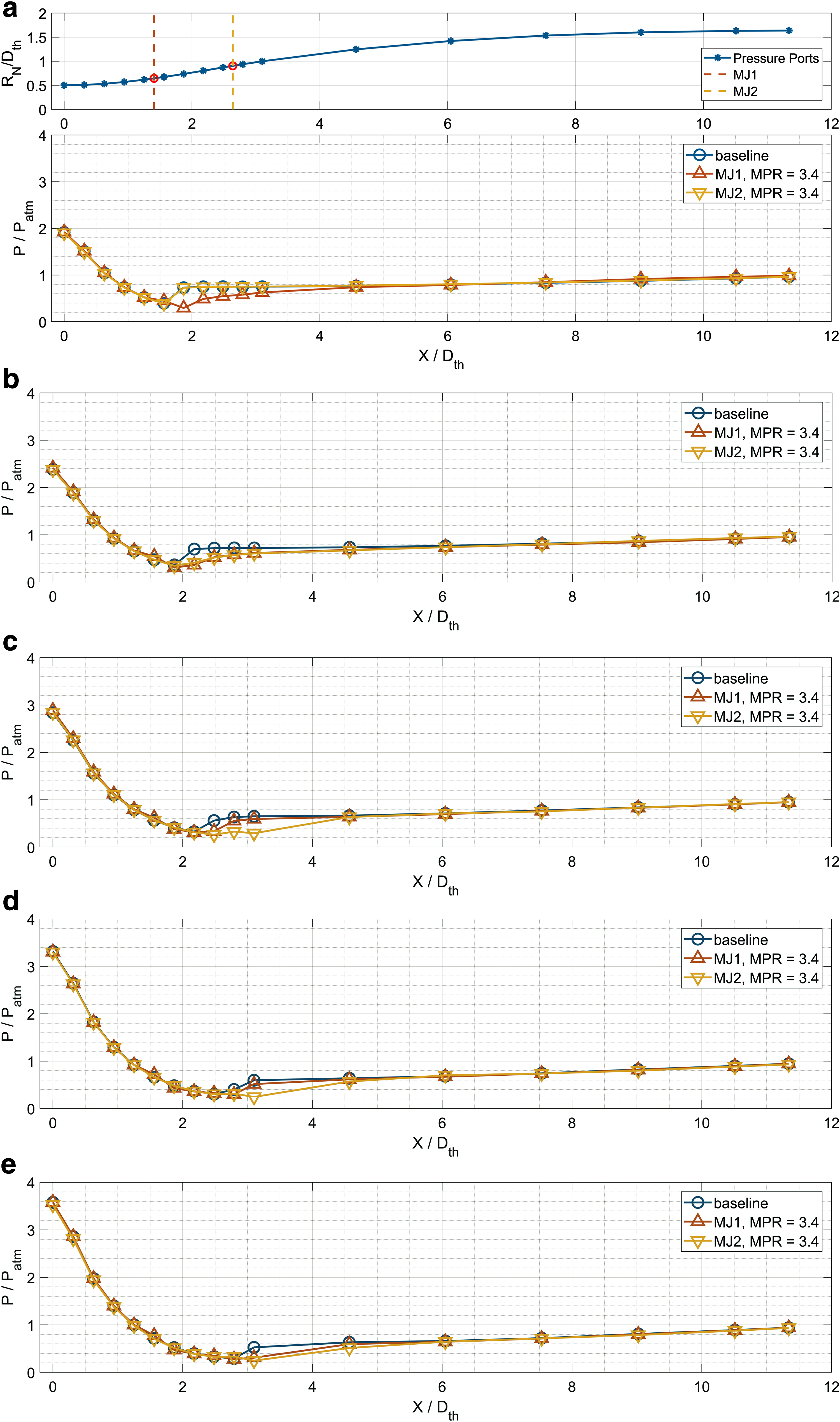
Effect of microjet injection location on pressure distributions.
At NPR = 5.0, both injection locations MJ1 and MJ2 are equally effective in modifying the pressure distributions and delaying the flow separation, which is an interesting observation, and suggest that microjets control is effective in delaying separation regardless of whether the injection location is slightly upstream or downstream, within a certain range, of the flow separation location. As we further increase the NPR to 6.0, 7.0, and 7.5, the effectiveness of location MJ1 reduces as compared with MJ2. These results indicate that the separation location moves downstream with an increase in NPR, the streamwise vortices generated by microjets at MJ1 are no longer effective and one needs to inject at MJ2, suggesting the need for an adaptive control technique, when NPR is varying.
Velocity Field for the Baseline and Controlled Jet
Velocity measurements were carried out in a plane normal to the jet at a distance of 1 throat diameter downstream of nozzle exit using stereoscopic PIV. The jet operating conditions for velocity measurements were NPR = 7.5 and TR = 1.0. This test condition was chosen for velocity measurements as the flow separation location is furthest downstream for this case. The normalized mean streamwise velocity contour plots for the baseline and microjet control cases are shown in Figure 11. The mean velocity (Vz) data have been normalized by the ambient speed of sound. In this case, microjet location MJ2 was activated for flow control. Also shown in these images are 2 circles corresponding to the throat (dotted circle) and nozzle exit (solid circle). For the baseline jet, the velocity is the maximum in the core and decreases sharply along the radial direction. Even at the measurement plane, which is at a distance of 1 throat diameter downstream, the jet diameter is less than the nozzle exit diameter. With microjet control, the flow field looks very different. The peak velocity in the jet core has been reduced but the jet has completely filled the nozzle at the exit. The decrease in velocity from the centerline along the radial direction is relatively gradual. This indicates a better mixing of high-momentum core fluid with the low-momentum fluid in the boundary layer of the nozzle.
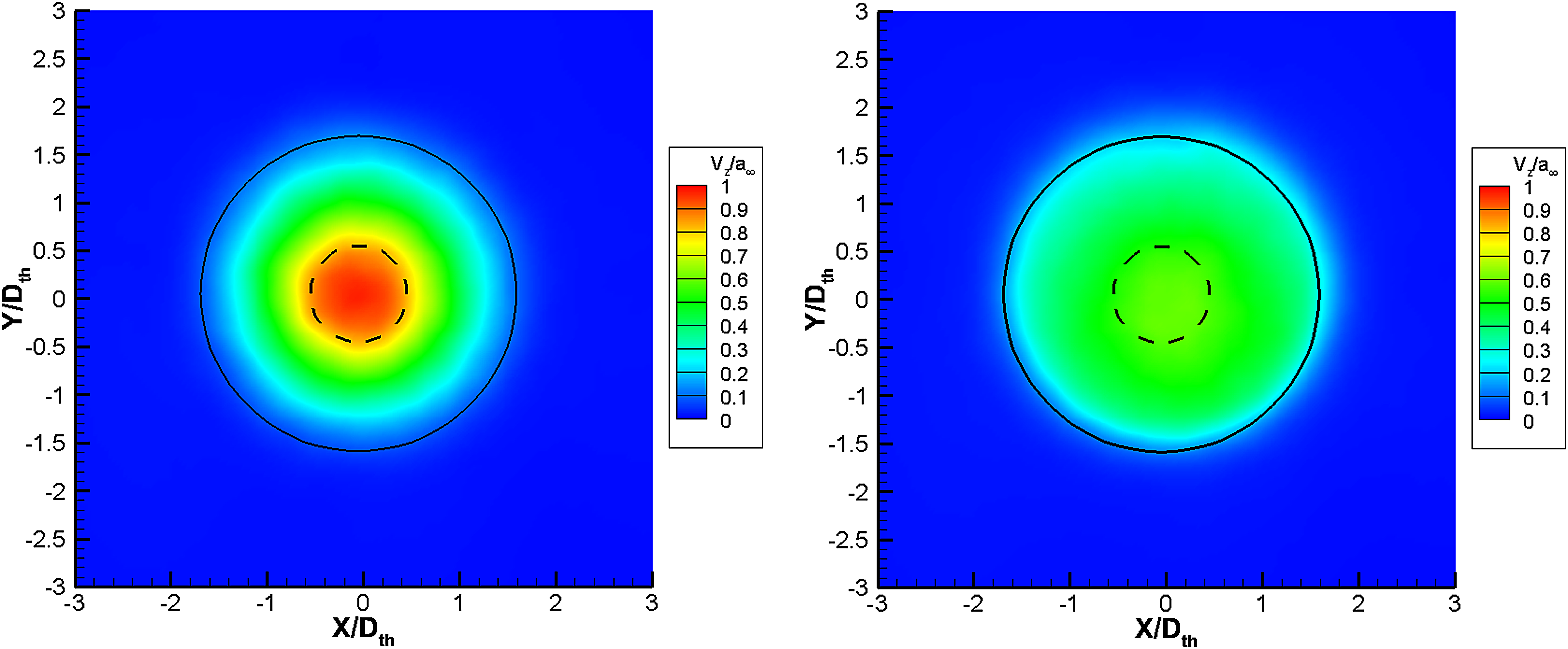
Average (normalized) streamwise velocity contours, baseline (left) and with microjet-controlled jet (right). Color images are available online.
To better understand the effect of microjet control on velocity field, velocity profiles are extracted along the horizontal lines at y/Dth = 0 and y/Dth = 1.2 as well as along the vertical lines at x/Dth = 0 and x/Dth = 1.2, and are plotted in Figure 12. The velocity profile for the baseline jet at y/Dth = 0 is Gaussian with a central peak and decreases radially, whereas with microjet control, it is more close to the top hat and fuller. At y/Dth = 1.2, the velocity levels for the microjet-controlled jet are much higher than for the baseline jet and the profile is much broader. Similarly, the velocity profile for the baseline jet at x/Dth = 0 is Gaussian with a central peak, whereas with microjet control the velocity profile is fuller. Also, at x/Dth = 1.2, the velocity levels for the microjet-controlled jet are much higher than for the baseline jet and the profile is much broader except that the peak with control seems to slightly shift downward. These results clearly indicate that with microjet control, the jet issuing from the nozzle is altered in terms of its development and mixing characteristics. Although not measured in the current tests, the velocity field suggests that noise levels of the jet with control will be significantly less than those of the baseline jet. We plan to make these measurements in future studies.

Velocity profiles extracted along horizontal and vertical lines for the baseline and microjet-controlled jets.
Conclusions
The baseline rocket nozzle experiences flow separation at all conditions under examination, leading to a reduction in efficiency. The flow separation location and the strength of separation shock are a function of NPR but remain unaffected by temperature within the range investigated. The surface static pressure distributions are modified and flow separation is significantly delayed with the implementation of microjet-based flow control. The location of the microjet array relative to that of the flow separation is critical to its efficiency and, therefore, the flow control technique needs to be tuned to nozzle operating conditions.
The velocity field measurements at a plane downstream of the nozzle exit show that the baseline jet diameter is less than that of the controlled case. These results suggest that the flow separation is reduced by the microjet actuation. The nature of the jet velocity profiles is significantly altered with flow control. In this study, a relevant range of pressures and microjet locations producing significant flow changes in the nozzle have been identified. In future testing, this range will be further explored to allow the optimum control strategy for thrust enhancement and stability of the vehicle. Furthermore, noise measurements will be carried out to quantify the effect of control on far-field acoustics and the associated frequencies in the nozzle flow.
Footnotes
Acknowledgments
This research is supported by the Federal Aviation Administration (FAA) Center of Excellence for Commercial Space Transportation (CoE-CST) Task 325 and Space Florida. The authors acknowledge the administrative and technical support of Mr. Ken Davidian and Mr. Nickolas Demidovich. The authors acknowledge the assistance of Mr. Jeremy Phillips for machining and Mr. Vikas Bhargav during PIV measurements.
Author Disclosure Statement
No competing financial interests exist.