
Abstract
Planetary Transportation Systems GmbH (PTS) is developing a second iteration of their lunar lander called Autonomous Landing and Navigation Module (ALINA)-2. With a wet mass of ∼4 tonnes, ALINA-2 will be capable of transporting 200 kg of commercial payloads from geostationary transfer orbit to the lunar surface. Several key enabling technologies are employed on ALINA-2. These include a 4 kN propulsion system, which provides the necessary thrust for the power descent maneuver (PDM) to the lunar surface and a total Δv of
Introduction
In recent years, national space agencies have begun to pivot their focus back to lunar exploration. NASAs Artemis program, European Space Agency (ESA)'s Heracles and In Situ Resource Utilization (ISRU) programs, and China's Chang'e missions will see the return of multiple landers and, potentially, astronauts to the lunar surface in the coming decade. Private commercial partners will play a key role in providing end-to-end logistic solutions to enable these agencies to realize their goals.
Services such as transportation of goods, development of lunar communication networks, the in situ extraction of resources, and the manufacturing of structures from lunar regolith will provide critical support to these agency-led missions. NASAs Commercial Lunar Payload Services (CLPS) program is already awarding contracts to American commercial lunar lander companies to deliver scientific payloads to the Moon.
Outside national agencies, public interest in lunar exploration is growing. This has been fueled in part by the 50th anniversary of the Apollo 11 landing, as well as the Google Lunar X-Prize, and the recent landing attempts by SpaceIL and Indian Space Research Organisation (ISRO). In addition, many private and commercial entities are seeking inexpensive access to the Moon. Their payloads are diverse, covering the spectrum from nontraditional such as art, advertising, and legacy projects to the more classic scientific and technology demonstration payloads. Against this background of increased agency and commercial demand for access to the Moon, numerous private companies have begun developing lunar landers.
Planetary Transportation Systems GmbH (PTS) is one such company. PTS has been developing lunar lander and lunar rover designs for the past 10 years. The cornerstone of PTS' lunar exploration ambitions is the Autonomous Landing and Navigation Module (ALINA)-2 lander. The original ALINA-1 was a small lander, with a payload capacity of less than
To achieve its mission objectives of a soft and accurate landing and the deployment of a pair of long-range rovers on the lunar surface, ALINA-2 leverages several key enabling innovations. These include:
a pulseable, high-thrust, multi-thruster propulsion system from ArianeGroup with thruster-out capability; a strong, lightweight, monolithic carbon fiber center core structure, which optimally distributes forces from the launch vehicle throughout the primary structure; a suite of guidance, navigation, and control (GNC) sensors, including a novel crater navigation system (CNav) for absolute position determination from the German Aerospace Center (Deutsches Zentrum für Luft- und Raumfahrt, DLR); a long-term evolution (LTE) base station developed by Nokia Bell Labs, which provides high-bandwidth, long-range communication capability for rovers and other remote surface operations.
ALINA-2 is currently at a post-preliminary design review status, with the design being refined ahead of critical design review (CDR).
Baseline Mission Overview
Although the eventual mission could vary, the baseline mission description is presented here for completeness.
Flight Phase
ALINA-2 will be launched into a highly elliptical orbit with an apogee altitude of about
Two mid-course correction maneuvers are foreseen, the first 24 h after TLI and the second about 24 h before lunar orbit insertion (LOI). The LOI will be one of the longest burns and ensures that ALINA-2 ends up with bounded motion in an elliptic orbit around the Moon with a periselene of
Landing Site
The baseline landing site is selected to be E 30.61436°, N 20.1960°, located at a distance of about 4.5 km west of the Apollo 17 landing site. The landing is planned for shortly after 6.81 h local true solar time, which corresponds to about 1 Earth day after sunrise at the site. Therefore, to fly above illuminated ground during the descent, the orbit of ALINA is retrograde, implying a landing from the East.
Additionally, for optimal navigation with DLRs CNav (see the Guidance, Navigation, and Control section), the Sun elevation angles for the entire landing trajectory of the subspacecraft point should be moderate (ideally between 10° and 50°). A landing azimuth of
Figures 1 and 2 show the baseline landing site and its 3-sigma error bounds (black ellipse). The dimensions of the 3-sigma error bounds are 500 by 750 m (see the Guidance, Navigation, and Control section). The along-track error is smaller than the cross-track error since the measurements that feed the navigation filter are taken in the flight direction. The red dashed line shows the incoming trajectory of ALINA-2 (103° orbital inclination), and the gray shows the baseline path of the PTS rover traverse (see the Rover System section).

An orthomosaic map of the baseline landing site.
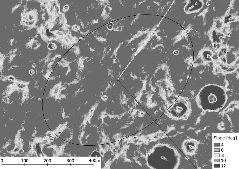
Terrain slope of the baseline landing site.
Figure 1 shows an orthomosaic map of the landing site, which utilizes data from the Lunar Reconnaissance Orbiter Camera. This area exhibits only few hazardous boulders and craters. The local terrain follows the global behavior of the valley and slopes downward South to East, with an average slope of just 3.54° across the landing ellipse. This is a valuable feature as ALINA-2 acts as an LTE base station throughout the surface mission and thus being higher up the valley provides favorable communication conditions (see the Communications section).
Across the landing ellipse, the local elevation changes by less than 100 m. Figure 2 shows all slopes smaller than or equal to 4° in blue and those larger than 12° in red; these areas are considered high risk and thus are minimized in the site selection.
The standard deviation of the mean slope is given as 1.96°, whereas the maximum slope of 15.82° is located close to the 3-sigma error bound of the landing ellipse. ALINA-2 is capable of handling up to 10.0° of slope.
This baseline landing site offers the best possible landing safety, good illumination throughout the mission, and favorable communication conditions and complies with the NASAs Apollo Heritage Guidelines.
System Overview
ALINA-2 is capable of landing at the equatorial region on the near side of the Moon (Fig. 3). The system is designed to carry up to
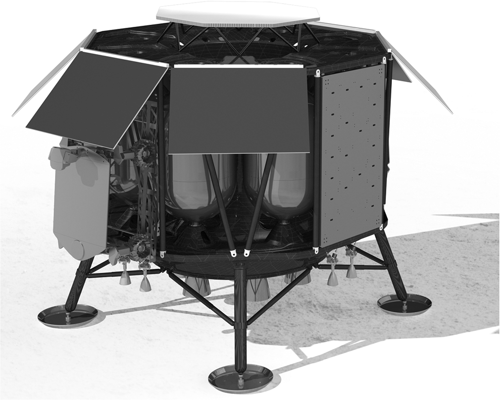
Rendering of ALINA-2. ALINA-2, Autonomous Landing and Navigation Module-2.
Table 1 summarizes the mass budget of ALINA-2. The platform consists of the following subsystems:
Mass Budget of Autonomous Landing and Navigation Module-2
Avionics
Communications
GNC
Power
Structure
Propulsion
Thermal control system (TCS)
Onboard software
Harness
The total platform mass is 1,155 kg, including design maturity margins and system margin of 20%. With a current payload mass of 200 kg, the complete dry mass of the lander is 1,355 kg. Adding the 3,000 kg of propellant, the total wet mass is 4,355 kg. With the given propulsion system, the delta-V capability is 3.5 km/s.
Propulsion
The propulsion system of the ALINA-2 spacecraft provides a thrust of more than 4 kN and a total Δv of more than 3,500 m/s for orbit transfer and landing maneuver. It is based on a conventional storable bipropellant design using monomethylhydrazine and mixed oxides of nitrogen as propellant, bypassing the thermal design challenges of cryogenic propellants while maintaining a reasonable specific impulse (ISP). This also allows the usage of commercial off-the-shelf parts and keeps cost and development time low.
The main engine assembly is composed of seven
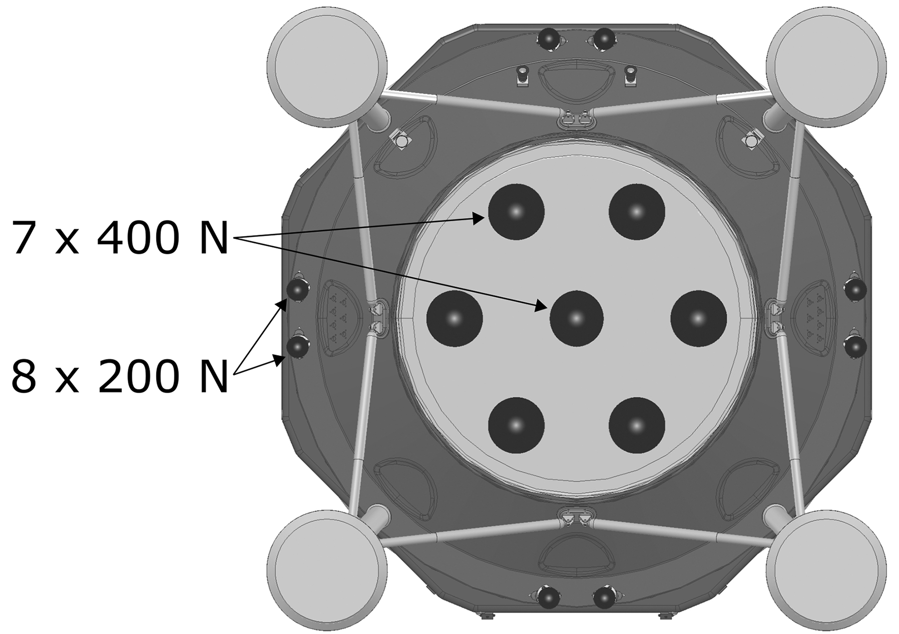
Thruster configuration of ALINA-2. ALINA-2, Autonomous Landing and Navigation Module-2.
Attitude control of the spacecraft is provided by a configuration of 8 body-mounted
Propellant is stored in 8 symmetrically arranged tanks, keeping the center of mass low and enabling a good landing stability. To simplify the design, all tanks have the same size and therefore a mixture ratio of
The propellant is pressurized at a constant pressure using a set of electrically operated pressure regulators. The regulators themselves are derived from an automotive valve that is normally used in liquefied natural gas cars. The mass production of the automotive counterpart and its extensive heritage not only lowers cost but also increases reliability. Furthermore, the electric operation of the pressure regulators offers more flexibility and the opportunity to optimize the performance of the engines in flight.
The propulsion system is rounded off by a comprehensive redundancy concept. It is capable of tolerating various control electronic failures, a single pressure regulator failure as well as a single 400 N engine failure. This results in a highly robust design increasing the spacecraft's reliability and de-risking the mission.
Structure
The manufacturing process selected for the main structure of the ALINA-2 uses a plain weave method for the Carbon Fiber-Reinforced Polymer (CFRP). The main advantage gained through this method is the much larger freedom for design, where the form follows function. This can be achieved without the additional measures required when dealing with complex geometry. This design freedom enables the development of a lightweight structure optimized by finite element analysis (FEA). Beads and increased material thicknesses were used throughout the monolithic parts to locally strengthen the structure where FEA identified critical locations, as shown in Figure 5.
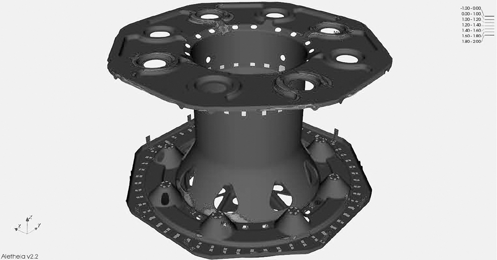
Plot—reverse factor primary loads including sloshing. 1
High-strength AS4 carbon fibers within the epoxy-based resins matrix Hexcel-8552 were selected, due to a low cost and high-strength mechanical properties. The topology of the structure is optimized for the primary loads during launch and landing phases (see Fig. 6). From these load requirements, several load cycles were conducted using an FEA. The main load path from the major mass elements to the launch vehicle interface was optimized using the design freedom provided through the use of plain weave CFRP material. This led to a main structure mass of
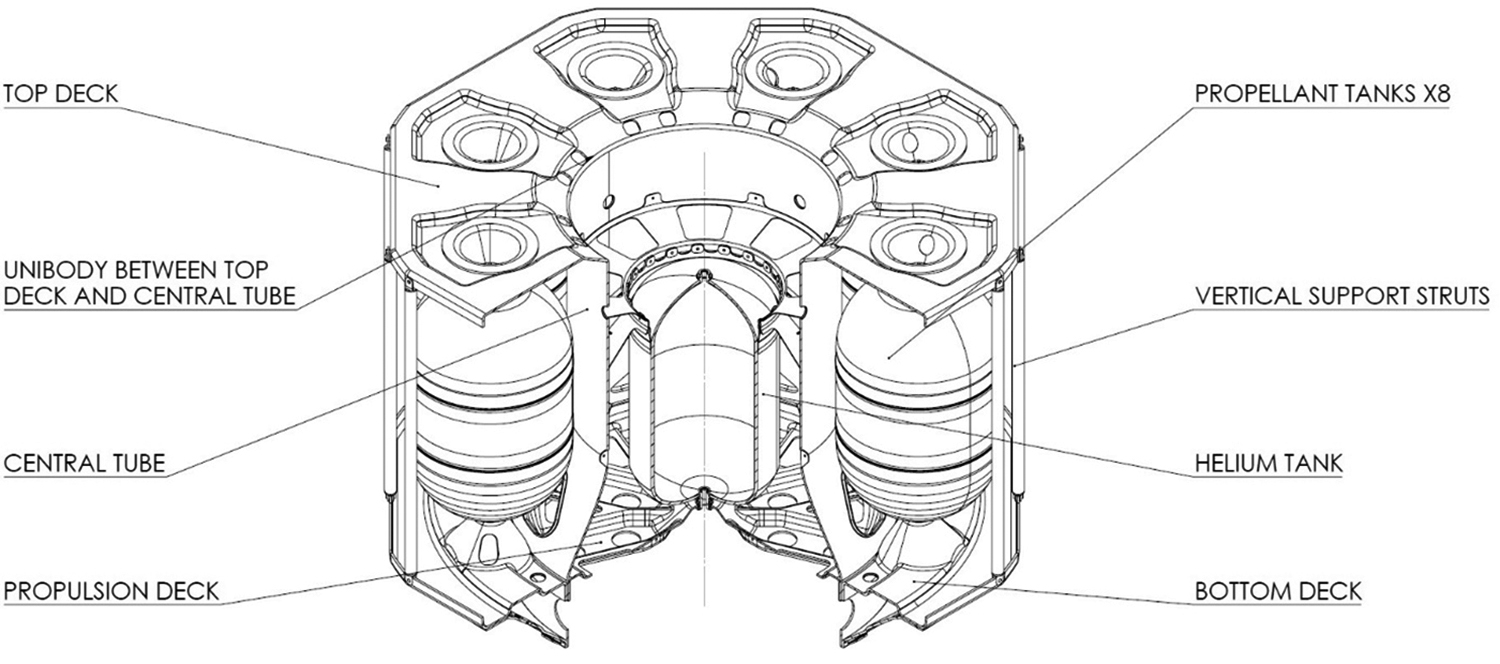
Main structure of ALINA-2. ALINA-2, Autonomous Landing and Navigation Module-2.
After the CFRP manufacturing process produces the parts, these parts will then be finished using a conventional milling process to help ensure the structure remains within the major tolerances required. This results in an overall dimensional tolerance of 0.1 mm over the entire main structure. Initially, the CFRP is produced thicker than required for the calculated design, and then, the additional unnecessary material will be reduced through the milling process. After this stage is complete, the structure will be baked out and afterward coated with a conductive coating to reduce the outgassing of the CFRP. Once the structure is optimized for the expected loads, the manufacturing cost goes down due to the reuse of the developed autoclave for producing the lander.
Guidance, Navigation, and Control
The GNC system has to both control the attitude of the spacecraft and track a reference trajectory for the powered descent. Therefore, the GNC will be controlling ALINA-2 from separation from the launcher to touchdown. Selecting the sensor suite and ensuring a reliable powered descent are the most challenging part of the mission in terms of GNC. At the current design stage, ALINA-2 is equipped with the following sensors:
Internal measurement unit
Fine sun sensors
Star tracker
Doppler radar altimeter and velocimeters
Short- and long-range laser altimeters
Crater navigation camera
The sensor suite is fully redundant. Of special interest is the choice of CNav, radar, and laser altimeters. CNav is a camera-based optical navigation system developed by DLR and offers a global, autonomous, absolute navigation update to the GNC system. Its working principle is based on the detection of craters in an image of the lunar surface and the subsequent matching of these craters to an onboard crater map. The algorithm works in a wide range of lighting and viewing angles. Given a sufficient abundance of detectable craters, CNav measures the spacecraft's pose in the Moon-centered Moon-fixed (MCMF) reference frame. CNav has been thoroughly tested and matured to Technology Readiness Level 6.2,3 Originally, for the ALINA-2 mission, it has been conservatively assumed that during the powered descent due to vibration-induced motion blur the CNav will not work.
Therefore, with the absence of an absolute navigation update, position knowledge continuously degrades during the powered descent until landing. However, the rate of degradation can be bounded significantly by direct velocity and range measurements. Therefore, a triaxial radar system capable of measuring line-of-sight velocity and range has been included in the sensor suite. The range requirement of the radar has been assumed to be
Additionally, a 1-directional long-range altimeter has been included. Its purpose is to deliver direct altitude measurements for adding safety and confidence to the PDI go/no-go decision. Therefore, it is configured to be nadir pointing during the descent orbit. Due to its range of 26 km, it starts providing updates approximately 700 s before PDI and further 250 s into the powered descent. After this time, the geometry of the trajectory drives the sensor out of its surface-relative angular working limits. For a safe landing, a direct, accurate, and high-frequent measurement of altitude is essential. Consequently, a second altimeter, pointing along the thrust axis and offering
Figure 7 shows the powered descent trajectory starting at time 0 s. At this point, it is assumed that CNav will stop working due to image motion blur induced by vibrations of the now running main engines. However, as explained above, the sensor suite has been designed to keep the subsequently growing position errors sufficiently small.
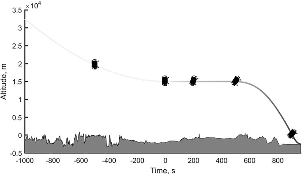
Powered descent trajectory. The last part of descent orbit is a coasting phase with the powered descent starting at 0 s. Image credit: GNC Department of the Institute of Space System, DLR Bremen. DLR, German Aerospace Center (Deutsches Zentrum für Luft- und Raumfahrt); GNC, Guidance, Navigation and Control.
One can observe that the guidance algorithm has the requirement to keep the altitude to
Figure 8 shows the sensor configuration of the ALINA-2 spacecraft. Simulations have shown that—assuming that CNav is nonoperational during powered descent—this GNC system configuration will enable landing within a 500-by-750-meter 3-sigma ellipse. However, recent experiments with image series taken from 3 actual Moon missions (including Chang'e-3) have demonstrated that CNav works well during powered descent maneuvers. 3 This improves the expected landing accuracy of the ALINA-2 GNC system significantly.

Sensor configuration as indicated: laser altimeters; sun sensors; star trackers; crater navigation; Doppler radar. Image credit: GNC Department of the Institute of Space System, DLR Bremen.
If adequate consideration is given to the need of the CNav camera to have a sufficiently large number of craters in its field of view during the majority of the landing trajectory, initial Monte–Carlo results from DLRs high-fidelity closed-loop simulator show an expected landing accuracy better than
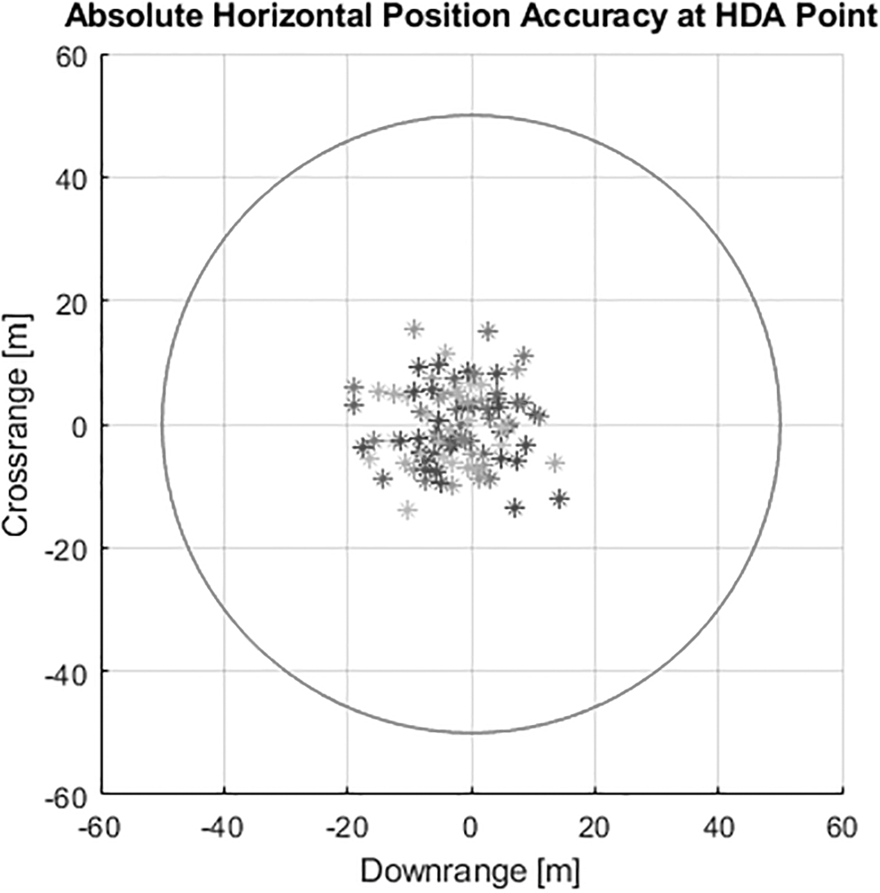
Results of a small Monte–Carlo test campaign (n = 100) in DLRs high-fidelity closed-loop simulator: absolute horizontal position accuracy at touchdown together with a 50 m landing ellipse.
The current baseline does not include hazard detection and avoidance (HDA), as there are large areas of sufficiently benign terrain available near the Apollo 17 landing site (see the Baseline Mission Overview section). However, if a landing site with a considerable risk to the lander is required, early experiments have shown that a HDA system is compatible with the GNC architecture. Figure 10 shows the expected accuracy of a hazard avoidance maneuver to be in the order of
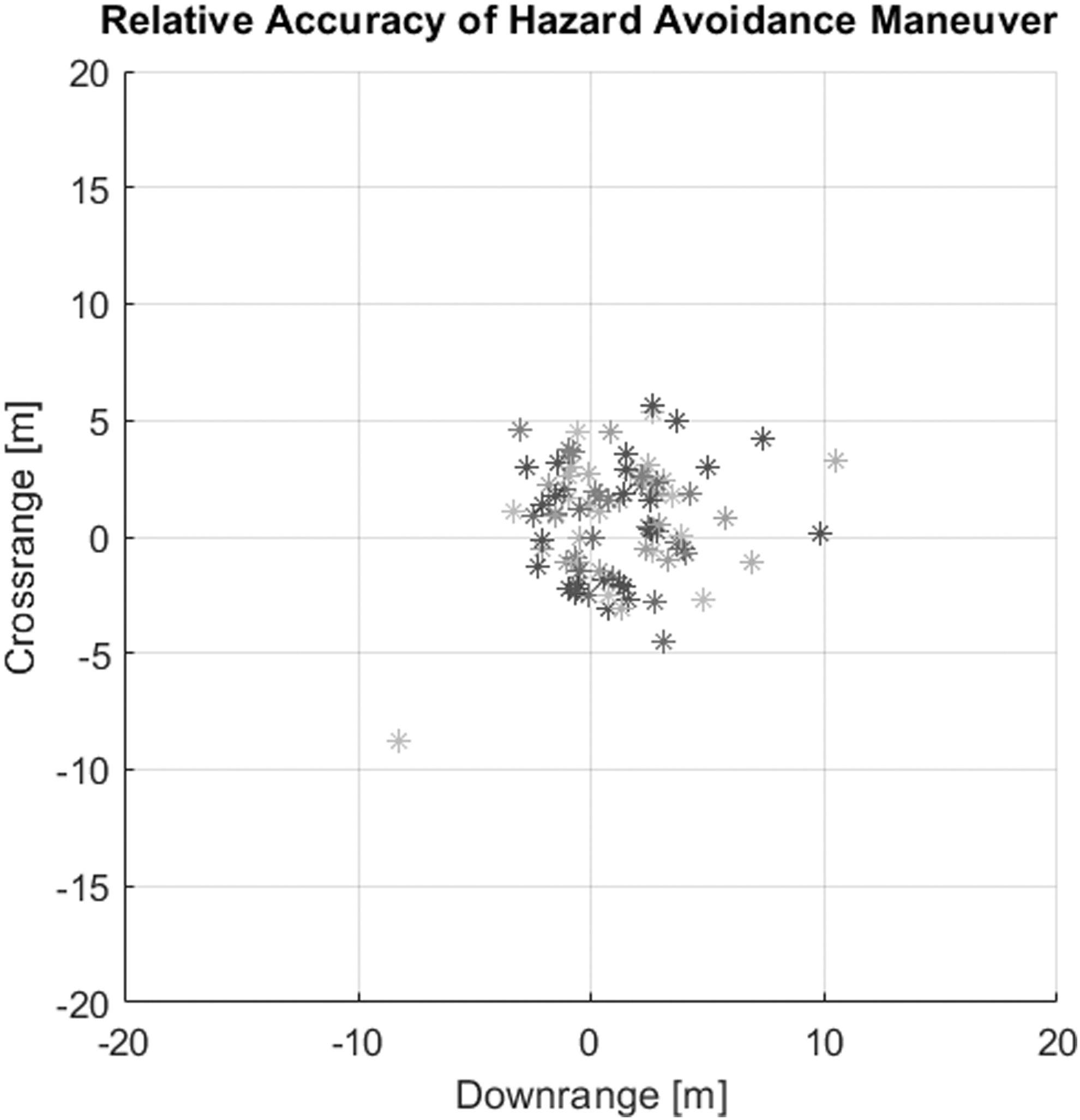
Results of a small Monte–Carlo test campaign (n = 130) in DLRs high-fidelity closed-loop simulator: absolute landing accuracy together with a 50 m landing ellipse.
In the simulations, only the second stage (at about
All computations will be executed on a dedicated GNC computer system, which is running in hot redundancy with its backup unit (see the Avionics section). For actuation of the spacecraft, ALINA-2 solely relies on the propulsion system as no reaction wheels are utilized (see the Propulsion section).
Avionics
The ALINA-2 avionics subsystem supports all required onboard data handling by employing a distributed modular architecture. It extends from the radio frequency (RF) interface at the communications modems to the actors and sensors that control and monitor the spacecraft. The architecture is split into the following functional blocks:
Onboard computer (OBC) block: this takes care of the RF-to-digital interface, monitors all other spacecraft computers, including the power conditioning and distribution unit (PCDU), and keeps track of spacecraft time.
The remote terminal unit (RTU) block: this offloads the OBC from data acquisition and autonomous control tasks such as that required by the TCS. It controls actuators with non-time-critical functions.
The ALINA GNC computer (AGC) block: this controls the spacecraft's GNC and propulsion equipment. It runs the GNC control loop, outputting commands to (and receiving feedback from) the propulsion control equipment based on inputs from the GNC sensor suite. This functions autonomously during landing.
The payload block: this controls the onboard cameras and video processing units, which allow live video to be streamed. It also has a dedicated Payload Computer for payload data handling and interfacing.
Figure 11 shows how these blocks are connected on a high level. The dark blue boxes show the spacecraft main computers, the light blue boxes show the additional computers, and the red boxes show the sensors and actuators.
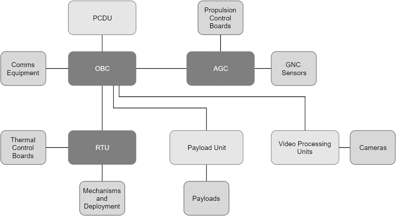
Avionics architecture of ALINA-2. ALINA-2, Autonomous Landing and Navigation Module-2.
The avionics supports a combination of autonomous control and ground-commanded control, with computers proving autonomy for constantly required critical functions such as thermal control and GNC. Ground-commands can be used for overrides and 1-time activation circuits. This loosens the requirements for ground station contact time and allows ALINA-2 to function when passing the far side of the Moon.
A distributed architecture is used due to the large size of the spacecraft and considerable number of onboard sensors and actuators; communicating with the sensors and actuators from 1 central unit would result in long cables, many with high voltages that are switched often, and cause electromagnetic interference (EMI) and noise on the harness lines. The modular architecture means that, for example, the payload can easily be switched for future missions with different requirements.
Almost all the avionics equipment is developed in-house, allowing for the re-use of components wherever possible. In the long run, this will drive down the cost of development and testing and increase the reliability within a shorter timeframe.
The mission-critical computers are redundant, with the OBC and RTU running in warm redundancy and the AGC in hot redundancy. All electronics are designed with radiation mitigation in mind; for example, radiation-tested components are used where possible, error-correcting codes are employed in computer memory, spot-shielding protects critical components, and redundancy with fast recovery rates allows for a quick and smooth switchover in case of error.
Communications
The spacecraft communicates with the ground via 2 RF interfaces: a bidirectional S-band link for (telemetry, tracking, and command) and a unidirectional X-band link for downlinking high-speed payload data.
To reduce costs and ease procurement, CubeSat modems are used. While they satisfy almost all requirements, they alone do not provide sufficient data rates to control and monitor such a large spacecraft and the distance of the Moon. Therefore, customizations are required to improve the equivalent isotopically radiated power and noise figure of the transmit and receive lines, respectively. Therefore, low-noise amplifiers and power amplifiers have been developed in-house to improve the attainable channel capacity.
As it provides the only means of commanding the spacecraft and determining its range from Earth, the S-band onboard architecture is designed for high reliability. Where line switching is required, active switches are avoided and replaced with passive power combiners and antennas with opposite polarizations. This removes the active single point of failure, at the cost of reduced link budget/channel capacity. Omnidirectional patch antennae are employed so that that the signal is received regardless of spacecraft orientation, meaning that the communications subsystem does not drive the spacecraft pointing requirements.
The X-band link is required for surface operations and is not used during flight. This means that, instead of using power-consuming amplifiers, a high-gain directional antenna can be used. As the spacecraft is stationary on the lunar surface, it is easier to point the small antenna beamwidth toward Earth. The link is primarily used to downlink the live video streams from the 2 rovers.
The rovers' primary communication downlink is LTE, a commercial mobile network used on Earth. Using ALINA-2 as a relay/base station relaxes the power consumption and/or pointing requirements of the rovers, as it removes the need for space-to-Earth transmission of high-data rate live video. LTE allows a large data throughput with low-power consumption, with the risk that it has not yet been proven in space. To counter this, a large development effort has gone into testing the base station, modifying the software, developing a robust redundancy scheme, and designing an appropriate housing with spot shielding.
The rovers are also equipped with backup X-band modems for direct-to-Earth communications. In the event of the rover-ALINA-2 or the ALINA-2-Earth links being disrupted, the rovers could be operated at lower bandwidth from directly from Earth via S-band for telecommand uplink and X-band for telemetry/data downlink (Fig. 12). This would preclude streaming video from the rovers, but a “photo-drive-photo” concept of operations could be envisioned as a contingency.
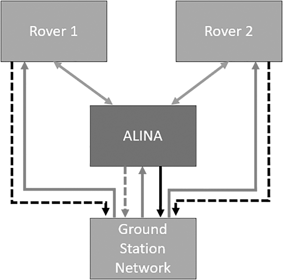
Ground to space to lunar surface link.
The interaction between communications nodes for surface operations is shown below, where LTE is represented in green, X-band in black, and S-band in red. Dotted lines represent the backup communication channels. The rovers and ALINA-2 share the same uplink S-band frequency, time-multiplexing it by discarding packets that are not addressed to their unique spacecraft ID.
The presented communication architecture provides a real-time end-to-end data service for payload operators. It does not only serve payloads attached to the spacecraft or the rovers but also supports mobile lunar payloads in the vicinity of the lander. Cloud-based ground interfaces provide access to the delay-tolerant network spanning from the ground to the space segment. This enables connections to the target node in space through automatic end-to-end routing with intermediate data storage and processing where needed. 4
Power
The power subsystem is designed to supply enough energy to the Spacecraft (S/C) subsystems and payload during all phases of the mission, which targets a maximum total mission duration of 2 months. The average power demand is expected to be
Due to ESA policy, RTGs cannot be used in Europe, and therefore, photovoltaic power was chosen as the source. Lithium ion batteries were chosen to be the technology used for energy storage due to their high specific energy density and heritage in the space environment.
To minimize the required area for the solar panels, they were distributed between the top deck of the spacecraft and on panels arranged in a fixed skirt configuration on 6 of the 8 edges of the top deck of the spacecraft with a 20° offset. The transfer of power from solar panel to the remainder of the power system was being done via a maximum power point tracking (MPPT) regulation. The other main form of solar panel regulation, direct energy transfer, is more reliable but dissipates extra energy as heat, whereas MPPT extracts energy from the solar panels as needed. Therefore, MPPT regulation was chosen due to the already challenging thermal conditions of lunar day time.
The power system architecture uses a decentralized power conversion scheme, meaning that the conversion of voltage levels occurs at the input to each equipment. This was done to maximize the efficiency of power transfer through the system, thereby reducing the required size of the solar array and to increase the reliability of the power system. This also has the advantage of simplifying the functions of the PCDU to control the distribution of power from solar array/battery to the S/C subsystems.
Power is delivered to each equipment through latching current limiter switches (LCLs). The function of the LCLs is to protect the power system by limiting and completely removing the power flowing to a subsystem in the case of a fault on the line outside the PCDU. Control of switches and reporting of power system telemetry is done by a field-programmable gate array within the PCDU, which communicates with the OBC.
Thermal Control System
The lunar thermal environment
The thermal design of the lunar lander ALINA-2 is driven by 2 major aspects. The first one is the thermal environment on the lunar surface and the second one is the technical design drivers.
At the preliminary landing site, the solar flux reaches up to 1,414 W/m2 at the Moon's perihelion of its orbit about the Sun, and 1,323 W/m2 at its aphelion. 5 The surface temperature is expected to reach a temperature not higher than 120°C,5,6 resulting in a lunar infrared (IR) flux of up to 1,314 W/m2. 5 The solar flux reaches the top side of the spacecraft nearly vertically with a deviation of 10°. Due to an albedo of up to 0.129, 5 the reflected solar flux at the landing site reaches up to 182 W/m2. The environment changes significantly during the lunar night: the direct solar flux and the reflected solar flux become zero, and the lunar IR drops down to 5.2 W/m2. 5 A similar environment, in which the external fluxes drop to nearly zero, is encountered in orbit during the lunar eclipse.
Technical and operational drivers of the thermal design
Besides the external heat fluxes, various technical aspects drive the TCS design of ALINA-2. The most prominent ones are:
The heat radiated from the main thrusters of the propulsion system forms a major heat leak.
During the power descent, the dissipation in the lander increases significantly for a short phase due to high-powered GNC sensors all powered on simultaneously.
Various pointing constraints have to be fulfilled for the communication, GNC, and power subsystem.
Due to its orientation to space after landing, different subsystems need surface area on the top deck, leading to a compromise between the radiator, the solar panels, antennas, and payload area.
TCS design
ALINA-2 was designed to satisfy these environmental and technical constrains. The spacecraft is wrapped in multi-layer insulation (MLI) based on vapor-deposited aluminum mylar. For the most outer layer, an aluminized polyimide was selected. This approach was chosen to thermally decouple the spacecraft from the extreme thermal environment of the lunar surface.
The interior of the spacecraft is divided into 3 thermal compartments:
The electronics compartment located on top of the spacecraft.
The propulsion compartment, which forms the major part of ALINA-2.
The 2 deployable rover bays on the sides of the lander.
The electronics compartment contains all the flight computers and other major S/C electronics. The TCS of the electronics compartment is designed to reject its heat via a radiator on top of the spacecraft. The radiator is oriented with an anti-nadir pointing. The radiator is finished with optical solar reflector, due to its high emissivity and very low absorptivity. 5 The need for such a high-performing thermo-optical material was driven by the direct solar flux impinging on the radiator surface. The location of the radiator on the top side of the spacecraft was enforced by the high IR fluxes originating from the lunar surface.
The electronics compartment is thermally decoupled from the propulsion compartment by MLI. The propulsion compartment contains hardware, which is required to reach the lunar surface but is no longer needed after landing. The compartment is thermally controlled until landing and is designed to maintain the nonoperational temperature limits of the containing hardware. Lacking a dedicated radiator for these components, the heat generation of infrequently used equipment with high dissipation, is buffered using phase change materials. Additionally, 2 thermally controlled rover bays are located on the sides of the spacecraft. These rover compartments will be opened after landing to deploy the 2 rovers. The thermal control of all compartments is achieved with an extensive network of redundant heater lines and temperature sensors.
The thermal environment of the Moon is extreme: from 120°C during lunar noon to around −170°C during lunar night. The baseline design of ALINA-2 does not include any technologies enabling lunar night survival. However, such an innovation would require the mitigation of heat loss through the main radiator and an energy source to keep the thermally insulated electronics compartment within its nonoperational temperature limits throughout the lunar night. Preliminary analyses show that the radiator could be blocked, and the electronics compartment is already insulated from the propulsion compartment. The lander would need to enter a low-power hibernation mode and autonomously wake up during the next lunar day. Further research into lunar night survival is recommended.
Rover System
To provide additional mobility on the Moon surface, the lander will carry 2 almost identical rovers that were developed in-house at PTS. Up to now, no other planetary mission has carried 2 identical rovers on the same lander. There are some definite advantages of having 2 rovers:
They are inherently redundant. If 1 rover fails, the second can complete the mission. This also allows them to be operated in a less risk-averse manner than most planetary rovers, which is important due to the distance they need to drive before lunar night.
Lessons learned on 1 rover, especially during deployment or navigating hazardous terrain, can be applied to the second, increasing its chances of success.
It is useful to have a second perspective. Any experiments conducted by 1 rover can be filmed by the other; any navigational challenges can be easily photographed from a second angle.
The baseline mission has both rovers traversing the lunar surface to the Apollo 17 Heritage Site. Photos and videos of 1 rover (taken by the second rover) in front of the Apollo artifacts would captivate worldwide audiences.
The rovers are stored in dedicated compartments on either side of the lander and will be activated shortly before the deployment. The deployment mechanism is realized with foldable rails. They will be deployed in sequence after ALINA-2 has safely touched down on the lunar surface. As both rovers are using the same platform, only 1 rover will be outlined hereafter from the system architecture's point of view. Several design iterations have resulted in a capable rover platform (Figure 13), which can accommodate commercial payload with a mass of up to
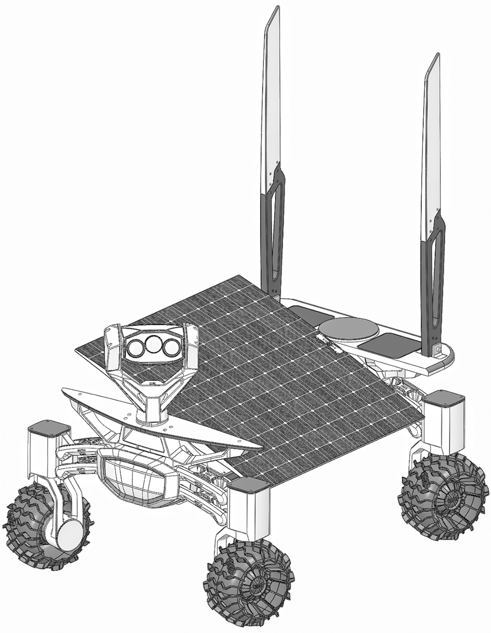
The latest PTS rover iteration. PTS, Planetary Transportation Systems GmbH.
Main Parameters of the Rover
LTE, long-term evolution.
The
Since the area of the solar panel is limited in size, a rotatable solar panel was the only way to stretch the lifetime toward a full lunar day without adding additional mechanisms and weight. The rover is designed to have the panel nominally orthogonal to the Sun. To improve efficiency the panel is not continually actuated, it is rotated by 1° roughly every 2 h. This approach will result in some non-nominal pointing of up to 1° causing power output from the panel to drop by 0.02%, which is an acceptable solution from the perspective of the power budget. The maximum power output of the solar panel can be up to 110 W.
All wheels can be driven and steered individually providing wide maneuverability when avoiding rocks at a nominal speed of around 1 km/h. Obstacles will be detected by several optical sensors placed in the camera head and the lower side of the rover. A fish-eye lens monitors all 4 wheels and will also be used to both monitor and record experiments being conducted during the mission. The elevated camera head carries 3 cameras including a stereoscopic camera pair and a telemetric lens. The remote sensing mast also serves as pan-tilt unit, which will help ground personnel to navigate the rover safely along its planned route. The field of view of the rover will hence fully cover 360° horizontally and
To add a scientific value to the first mission (independent of commercial payload), the camera head is equipped with 11 different optical filters, which can be combined with the center camera both individually and by pairs. All high-definition (HD) image sensors cover a VIS+NIR spectrum between 400 and
Even though the rovers are designed for 1 lunar day only, they will be put in hibernation mode to investigate how robust the platform is toward the severe temperature drop during lunar night. Mission operations are therefore already planning to ensure a stable Earth-rover link beyond the baseline mission timeline to download valuable housekeeping data for future rover missions.
Payloads
PTS believes in making access to space and the Moon available to all, owing to which the ALINA-2 spacecraft is designed to transport and deliver a total payload capacity of
The extensive selection of possible services makes ALINA-2 suited to delivering a wide variety of payloads including, but not limited to:
Scientific experiments
Robotic missions
Technology demonstrators
Rovers and mobile payloads
Lunar orbiters and surveyors
The focus for most payloads is resources detection or ISRU-related, which is confirmed by the kinds of payloads requested not only by space agencies and other public entities but also by the commercial space-related and non-space companies. The most recent payload manifest has multiple small rovers, a laser regolith manipulator, a gravimeter experiment, lunar CubeSats, material sciences payload, and multiple visual inspection payloads, to name a few. This showcases the diversity of payloads that can be hosted onboard the ALINA-2 spacecraft.
Lunar Lander Market
With the large lunar transportation programs such as the NASA Human Landing System Program (HLSP) and the ESA's European Large Logistics Lander (EL3) focusing on bringing humans to the lunar surface in large, pressurized, and complex landers, there will be significant support necessary to bring small to mid-size cargo to complete and support the human lunar habitation systems. This is baselined on the assumption that the benefit on the “economies of scale,” owing to the large deliverable payload volumes, which can be achieved through the heavy landers, will most likely be trumped by the cost of operations, manufacturing, and turnaround frequency required for the complex and heavy landers.
PTS believes that mid-size landers will dominate the lunar transportation landscape, at least for the foundational years of the lunar base, which is also substantiated with the contracting approach undertaken by NASA between the CLPS and HLSP program awards. CLPS awards are pinned as mostly “high risk, high reward” where a plethora of newer and smaller companies, in some cases with no flight experience, has been allowed to be involved and develop mid-size landers. However, the HLSP awards are focused on traditional space companies, with strong engineering and project management capabilities, also in consortia.
The market for mid-size lunar landers is directly translatable from the launch vehicle market, where small to mid-size launch vehicles dominate the launcher market in terms of payloads flown, and the heavier, much more expensive launcher capabilities are reserved for dedicated and/or critical mission profiles.
Conclusions
National space agencies continue to push forward with plans to return to the Moon: the U.S. Artemis and CLPS programs continue apace; China and India continue their lander programs; and the international space community has begun to develop the Gateway cislunar space station. On the commercial side, the American companies Astrobotic, Intuitive Machines, and Masten Space have all been awarded CLPS contracts from NASA to deliver scientific payloads to the Moon—and more CLPS awards will followed. Many hope this wave of missions herald the start of a true lunar economy, which will pave the way for a sustained human presence off-world. As one of a small handful of non-U.S. commercial landers, ALINA-2 is well positioned to play a role in such a lunar economy.
The recent failures of the Beresheet lander from Israel and the Vikram lander from ISRO have underscored the fact that landing safely on the Moon presents a real technical challenge. In both cases, the root causes of the failures helped to inform ALINA-2s design: fully redundant avionics and GNC sensors, an autonomous descent mode, and a propulsion system capable of landing with a single failed thruster. Other innovations, including ALINA-2s LTE surface communication system, a robust TCS, and a lightweight carbon fiber center core structure, make it a capable candidate for future robotic lunar missions. Nevertheless, depending on its eventual mission profile, the system may need adaptations to meet mission requirements. As ALINA-2 moves toward CDR, the system design will continue to change and be refined, but the eventual lunar lander design is certain to be innovative.
Footnotes
Author Disclosure Statement
No competing financial interests exist.
Funding Information
No funding was received.
Address correspondence to:
Planetary Transportation Systems GmbH
Plauener Strasse 160B
13053 Berlin
Germany