
Abstract
Various methods of water recovery for the life support system for deep space missions are analyzed. It is shown that the use of membrane technologies does not allow achieving the desired results both in terms of the level of water recovery and energy consumption. The advantages and disadvantages of the centrifugal distiller installed on the International Space Station are analyzed. Its water recovery is only 85%, which does not allow the use of this system for deep space missions. The experimental results of the centrifugal multiple-effect distiller study are shown. It is able to recover 92% of the water from the solution without any deposits on the heat transfer surface; the specific power consumption varies from 90 to 160 W∙hr/kg in a 3-stage distiller and from 70 to 120 W∙hr/kg in a 5-stage distiller. The technologies that allow extracting water from the obtained brine up to 99% are reviewed.
INTRODUCTION
NASA, SpaceX, and other companies are planning space missions to the Moon (duration: 30–180 days) and Mars (duration: 30–575 days) in the coming years.1–4 A NASA document states that a crew of 4 astronauts requires 41 L of water per day (excluding laundry). 5 Only a 100% water reserve could guarantee the absolute reliability of the water supply system. However, delivering 1 kg of cargo to the International Space Station (ISS) costs >$2,000. 6 With a daily need of 41 L of water, a 600 day-long mission would require 24,600 L of water. Obviously, it is an impossibly heavy cargo. Long-term expeditions to the Moon and Mars require an effective and reliable system for wastewater recovery from urine, humidity condensate, hygiene, and laundry.
The 2-stage water recovery is considered to be the most efficient to date.7,8 At the first stage, the bulk of the wastewater is processed from the initial concentration to the beginning of salt precipitation (up to ∼90%–93%). At the second stage, the water evaporates forming solid salts, ideally until dry residue. Such water recovery system is used at the ISS, where the vacuum compression distiller (VCD) recovers water to 85%, and the ionomer water processor (IWP) then takes the recovered brine and evaporates the remaining moisture.
Apart from the water recovery technologies used at the ISS, many companies are working on creating alternative water recovery systems and technologies fit for use in space. This article presents a brief review of these technologies and an analysis of the future of their use in long-term space missions.
OVERVIEW OF FIRST-STAGE WATER RECOVERY TECHNOLOGIES
Membrane Technologies
Membrane technologies include reverse osmosis (RO), electrodialysis, and the Thermoelectric Integrated Membrane Evaporator System (TIMES). Basically, such technologies involve either a direct treatment of wastewater when it passes through the membrane, or a retaining of the deposits by the membrane when the water evaporates from the surface of the membrane.
Reverse osmosis
This technology has been around for >60 years. It is widely used in seawater desalination systems, power engineering, and domestic applications, to obtain clean drinking water and water for injections in pharmaceutics. Naturally, over the years, the main component of the technology—the membrane—has continued to improve. The characteristics of an RO system are mostly affected by the required permeate quality and the recovery rate. The salt concentration in urine (40–50 g/L) is close to that in ocean water.
For such feed liquids, modern membranes provide a water recovery of no more than 30%–40% at a pressure of the main pump of 30–40 bar. Increasing the recovery rate deteriorates the quality of the resulting water. The possible use of RO for water recovery in zero gravity is described in multiple publications.9–11 The main shortcoming of the RO: the membrane tends to foul rapidly due to precipitation of constituents of limited solubility, and biological growths over membrane surfaces. 12
A typical RO-based recovery scheme was experimentally tested. 13 The authors recycled sanitary water with a 1,200 ppm salinity and obtained data on the flow rate and pressure in the loops, the amount of the feed liquid and permeate. Specific power costs amounted to about 1 kW∙hr/kg.
Many researchers keep investigating and searching for better membranes to reduce the impact of fouling on recovery efficiency. Most of those studies deal with using RO in non-space scenarios. It was also demonstrated how different types of membranes affect the humidity condensate processing. 14 The analysis of the known publications allows concluding that membrane technology cannot be used as the main element of water recovery systems used in spaceflight.
Electrodialysis
This is a simple technology using direct current to separate salts and water through a semipermeable membrane.15,16 It requires low power consumption, has small size and weight, and is widely used for desalination of salt water. However, electrodialysis is not very efficient when dealing with calcium salts. As is the case with RO, this technique, too, requires pretreatment. The membrane fouling problem is also present. An article describes a technology for the future manned space exploration missions with a capacity of 0.4 kg/day with power consumption up to 17.4 kW∙hr/day. 17
Thermoelectric Integrated Membrane Evaporator System
The TIMES technology was developed by Hamilton Standard in 1980, and occasional publications devoted to improving its characteristics keep appearing until today.18–21 Unlike the technologies described earlier, TIMES includes a thermoelectric device. This device consists of special semiconductor elements heating up on one side and cooling down on the other, due to the Peltier effect. Both sides of the device are covered with membranes. On the hot side, the feed liquid is heated and evaporated, and on the cold side, the resulting vapor is condensed in a membrane device. The process occurs in vacuum. The efficiency of such a heat pump depends on the temperature difference at the hot and cold sides of the device, as well as on the electric current supplied to the device.
The TIMES technology is simple and effective at low water recovery (up to 30%). But as soon as the recovery goes beyond 20%, the temperature depression exceeds 2°C, which increases the temperature difference across the device. As a result, productivity rate drops by half (from 1 kg/hr to 0.5 kg/hr, Fig. 1). 19 This increases the specific power consumption (SPC) up to 200 W‧hr/kg. A report also shows a high (up to 257 mg/L) ammonia concentration in the distillate. 21 Another important point is that ensuring the durability of the TIMES equipment is rather difficult. As with other systems using membranes, this device has an unresolved issue of removing salt particles from membrane pores.

TIMES productivity at different solids concentrations. TIMES, Thermoelectric Integrated Membrane Evaporator System.
Centrifugal Thermal Distillation
The first centrifugal evaporator for seawater recovery was patented in 1957.22,23 The authors of one of the studies describe in detail the technique for calculating heat transfer during recovery on a rotating disk surface and evaporation of a liquid film during laminar flow on a rotating disk. 24 Another study describes the experimental results on the multistage disk centrifugal distiller with a production rate of >1 m3/h used to recover a NaCl solution and sea water. 25
High heat transfer coefficients (up to 10,000 W/m2∙deg) and the use of a multistage evaporation process allowed for a lower power consumption compared with falling film evaporators (multi-effect distillation, MED). However, due to high capital cost, such distillers were not used for salt water desalination, since they could not compete with the RO technology that appeared at the same time.
Today, centrifugal distillers are used for producing medicines, fruit juice concentration, and making of freeze-dried products (coffee and tea).26–28 The use of centrifugal forces makes it possible to reduce the contact time of the thermosensitive liquid with the heating surface, which allows excluding the destruction of the treated solution and reducing the likelihood of deposits.
Vapor compression distiller
In 1962, researchers in the United States began developing a single-stage centrifugal distiller with a mechanical vapor compressor for zero-gravity conditions. NASA reports describe in detail the design of the distiller (Fig. 2) and the schematic diagram of the system (Fig. 3), presenting the test results obtained before the VCD was delivered to the ISS. The average production rate is about 2 kg/hr.29–32
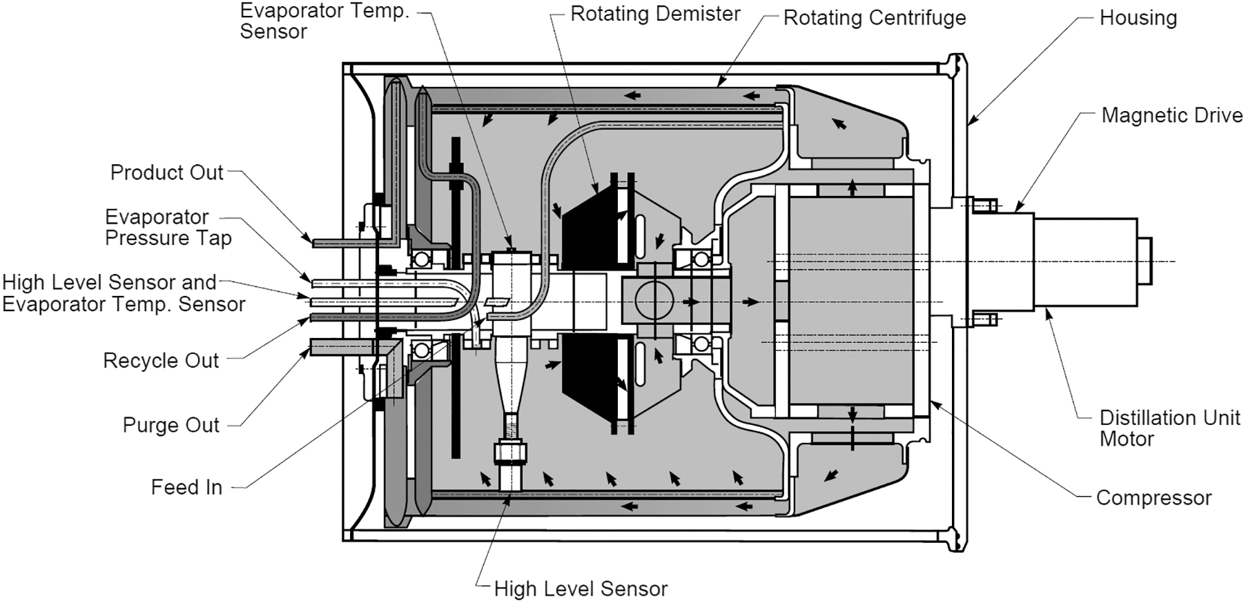
VCD distillation assembly schematic. 32 VCD, vacuum compression distiller.
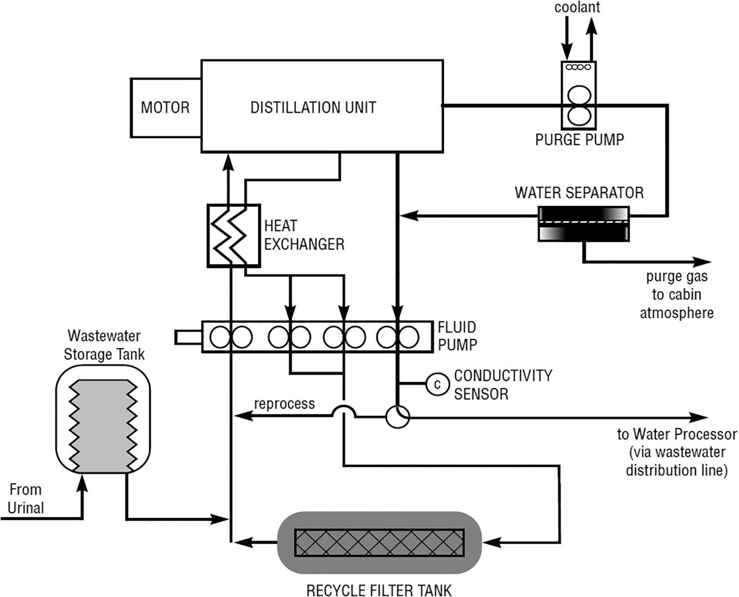
Schematic of VCD process. 32
Inside the VCD, there is a rotating drum. The wastewater is fed into the drum through a fixed inlet, spreading the liquid into a film over the inside surface of the drum. When the vacuum pump is turned on, part of the film evaporates. The non-evaporated part of the liquid flows into the loop channel, from which a pitot tube feeds it back to the distiller through the circulation loop. The resulting vapor is sucked through a separator into a mechanical compressor, where it is compressed to a specified pressure and condensed on the outer surface of the drum.
The condensate collecting in the loop channel outside of the drum is taken out to the external loop and enters the storage tank through the distillate control valve. The liquid flow is circulated through the distillation system by a set of peristaltic pumps. The liquid keeps returning through the tubes to the distiller until it reaches a required recovery. Then, the valve interrupts the supply of liquid to the distiller, and the obtained brine is drained into a separate container.
This VCD design has some drawbacks. Owing to its properties, urine is classified as a heat-sensitive liquid, thus a contact with a heating surface may cause Ca+ and Mg+ salts deposition. Salt precipitation has already been recorded during operation on the ISS. 33 To prevent the precipitation, the pretreatment procedure was changed. 34
Low rotor speeds (180 rpm) do not allow for good vapor separation, leaving a possibility of drops of the feed solution getting mixed into the condensate. This has been repeatedly observed when operating the VCD on the ISS. 34 The single-stage VCD circuit and compressor design do not allow changing the capacity and pressure drop in the compressor. At the same time, an increase in water recovery from 20% to 50% leads to a 2-fold increase in SPC (Fig. 4). 31

SPC based on recycle loop solids concentrations. SPC, specific power consumption.
Moreover, the design of the mechanical compressor did not prove to be very efficient. Throughout the entire period of operation, the VCD experienced failures due to drive belt slippage.34,35 Belt issues are major ones, since their elimination is impossible without dismantling the system, which is very problematic in spaceflight conditions. Another problem concerned urine leakages from the inner space into the space between the rotating drum and the fixed outer housing.
The VCD system processed >13 tons of water for 15 years, which made it possible to significantly save on the water delivery from the Earth. However, these design flaws do not allow a recovery of >85%, which is insufficient for long-term space missions.
Centrifugal multiple-effect distillation
The development of centrifugal multiple-effect distillation (CMED) began at the Kyiv Polytechnic Institute (Kyiv, Ukraine).36,37 Initially, the distiller had 3 stages (Fig. 5).
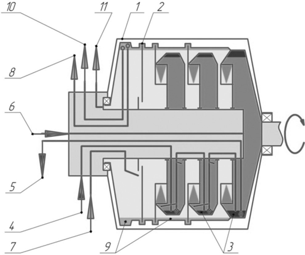
Schematic of 3-stage centrifugal distiller: 1—housing; 2—rotor; 3—feed solution; 4—feed solution inlet; 5—outlet channel; 6—supply channel; 7—cooled condensate inlet; 8—heated condensate outlet; 9—condensate; 10—distillate product outlet; 11—gas outlet.
The distiller has a sealed housing 1 with a rotor 2 mounted inside it on ball bearings. A sealed magnetic drive rotates the rotor, which is divided by partitions into a number of distillation stages and a condenser. The feed solution 3 is fed through channel 4, where it is distributed among the distillation stages. The solution is fed through channel 5 to the heater of the system, from which it returns (in an overheated state) through channel 6 to the device, where it boils. The resulting vapor serves as a heating agent in the preliminary stage.
The vapor from the last evaporation stage condenses in the condenser in contact with the distillate. The distillate, in turn, is cooled on the cold side of the heat pump and in an additional heat exchanger. The cooled distillate enters the device through channel 7, gets heated and returns by a built-in pump through channel 8 for cooling. Excess condensate 9 (distillate and product) is transported through a pitot tube through the channel 10 into the storage tank. The device is evacuated through channel 11.
The 3-stage distiller manufactured in 1986 is still being used for laboratory research today. Over this period of time, the device has worked 1,240 h on various liquids: water, NaCl solution, urine, and urine+condensate simulator. The device performed 856 start–stops, and throughout this entire operating period, rotor ball bearings were replaced only once. The distiller was disassembled only a few times after long (several years) periods of idleness. In those cases, the device was disassembled to replace the sealing rings. 38
In 1999, KPI, together with Termodistillation Co (Kyiv, Ukraine), received an order from Honeywell (USA) for the development and manufacture of a new 5-stage centrifugal distiller with a thermoelectric heat pump (THP) (Fig. 6). 39 The new device was called the centrifugal cascade distiller (CD), and the entire system is referred to in publications as the centrifugal distillation system (CDS). Over the years 2000–2003, 2 CD+THP systems were manufactured, and another 5-stage CD was made and tested on the NASA test stand in 2005.39–43 The THP was manufactured by ALTEC (Chernivtsi, Ukraine).
CMED with thermoelectric heat pump. CMED, centrifugal multiple-effect distillation.
The test results from the NASA Johnson Space Center (JSC) are presented in different articles.44–49 The following mixtures were used as the feed solution: urine+condensate and urine+condensate+sanitary water. In total, 1,750 L were processed, 1,467 L of distillate were obtained, recovery was 93.4 ± 0.7, and productivity was 4.1 kg/hr. According to the authors, the mass of the processed solution corresponds to the amount required for a crew of 4 people during a 27- to 28-day flight to the Moon.
One study notes the good quality of the recovered water and the normal functioning of the distiller. 45 Notable are the matching main characteristics—productivity, SPC, and distillate quality—of the 3 manufactured centrifugal distillers and 2 heat pumps (for the same feed liquid parameters, rotation speed, and power). 50 This guarantees the predictable behavior of the developed CMED design in combination with the THP when manufacturing flight samples.
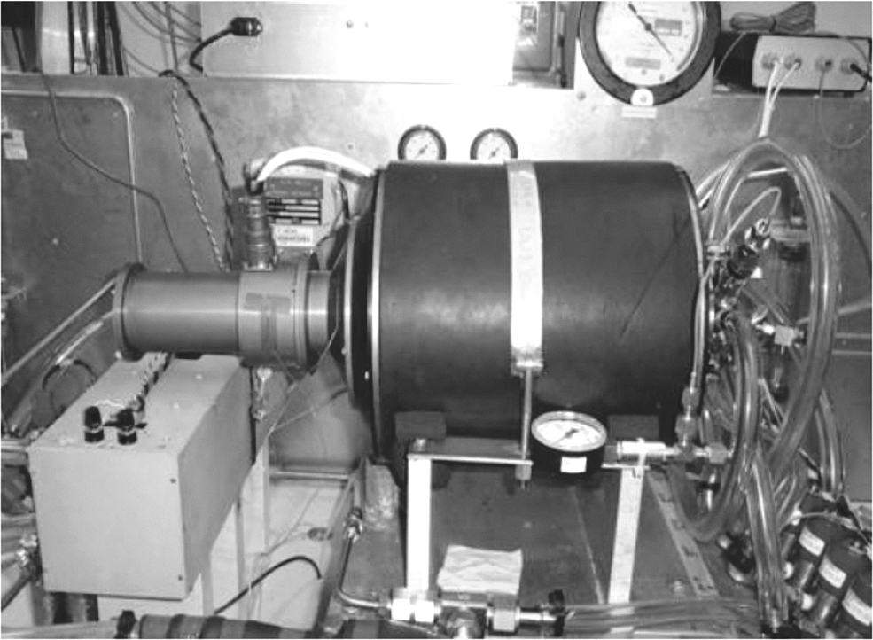
Five-stage distillers were also tested at KPI.51–55 Figure 7 shows a schematic diagram of the test stand. The main and auxiliary equipment of the stand are connected by a system of 2 loop pipelines. The processed solution circulates through the hot loop, whereas the distillate flows through the cold loop.

Schematic of the test stand: 1—centrifugal vacuum distiller; 2—THP; 3—heat exchanger/cooler; 4—feed solution; 5—distillate collector; 6—power control valve; 7—vacuum pump; 8—brine gauge; 9—electronic scales; 10—vacuum gauge; 11—container with distillate for filling cold loop; 12—containers for draining loops. THP, thermoelectric heat pump.
The stand works as follows. The motor 1 of the distiller is turned on, providing the specified speed of the distiller's rotor, whereas the vacuum pump 7 sets the necessary pressure in the device, which corresponds to the specified boiling point of the solution. The tank 11 with distillate fills the cold loop, where the distillate circulates passing through the condenser of the distiller 1, the salt gauge 8, rotameter, the cold end of the THP 2, the heat exchanger/cooler 3, before flowing back to the distiller's condenser. The hot loop is filled from the tank 4 with feed solution to the level set by the control valve 6. In the hot loop, the solution circulates from the evaporator of the distiller 1 through the rotameter, the hot side of the THP 2, and back to the evaporator of distiller 1.
When power is supplied to the THP 2, the condensate in the cold loop cools and the solution in the hot loop heats. The solution superheated in THP 2 relative to the saturation temperature in the CMED evaporator 1 partially evaporates and the vapor serves as a heating agent in the subsequent distiller evaporation stage; the vapor obtained at the last distiller stage is condensed in the CMED contact condenser 1.
During the evaporation process, the concentration of dissolved substances in the hot loop increases. Excess distillate from the cold loop is automatically drained to the distillate collector 5. The solution is replenished through the valve 6. To ensure the stationarity of the distillation process, excess heat is transferred by the heat exchanger/cooler 3 to the environment.
After the end of the experiment, the power supply to the THP 2 is shut down, and the cold and hot loops are drained into the corresponding containers 12.
The temperature was measured at the inlet and outlet of the thermopile on the hot (T1 and T2) and cold sides (T3 and T4), after the heat exchanger/cooler in the cold loop (T5) and at the inlet and outlet of the heat exchanger/cooler on the cooling side (T6 and T7). The temperature in the hot and cold loops was measured by chromel-copel thermocouples with a measurement accuracy of ±0.1°C.
The pressure in the device was measured with a vacuum gauge 10 with a measuring scale of 1…0 bar (accuracy class 1.0) complete with a barometer.
The mass of the obtained product and the feed solution was measured by electronic scales with a measurement accuracy of ±2 g and a measurement range of ±10 kg.
The salinity in the cold loop was measured with a Hanna salt meter (0–999 ppm).
The power of the motor and heat pump drive was measured with a voltmeter and an ammeter (accuracy class 0.5). The speed of the motor was measured with a tachometer with an accuracy of ±1 rpm. One test lasted 60–120 min.
The rotation speed of the heat exchange surface varied from 900 to 1,300 rpm, the power of the THP varied from 100 to 600 W. Distilled water and fresh urine were used as working fluids. The purpose of these experiments was to study the influence of the speed n, the power of the heat pump NTHP and the engine Ncd, and the recovery rate on the production rate of the distiller and the quality of the distillate.
The heat flux generated at the outlet of the heat pump Qh, W, is defined as
where T2 and T1, respectively, are the temperatures at the outlet and inlet of the THP, °C (Fig. 7);
ηTHP is the coefficient of performance (COP) of the THP and is defined as

SPC, W∙hr/kg, is the specific power consumption defined as the total supplied power (the power supplied to the distiller's motor and the power supplied to the THP) spent on the production of 1 kg of distillate
Table 1 gives the essential experimental parameters for a selection of tests. In the tests, recovery ratio was 0.89–0.91. The quality indicators of the obtained water corresponded to the drinking water quality standards.52,55
Main Results of the Test Study
SPC, specific power consumption; THP, thermoelectric heat pump.
Table 1 draws attention to the following fact. When the power of the THP NTHP decreases, the SPC decreases also, provided all other parameters stay the same. For example, at NTHP = 200 W, SPC = 83 W∙hr/kg, Gd = 3.2 kg/hr, at NTHP = 400 W, Gd = 4.8 kg/hr, and at NTHP = 600 W, Gd = 6.2 kg/hr. This allows saving power. For example, 6 L of clean water can be obtained in 2 operating modes of the distiller.
1st mode: NTHP = 600 W, engine power is 80 W at 1,100 rpm, distillation duration is 1 h, total power consumption is 680 W.
2nd mode: NTHP = 200 W, engine power is 80 W at 1,100 rpm, distillation duration is 2 h, total power consumption is (200 + 80)‧2 = 560 W.
In the second mode, the power is saved due to the fact that a lower power (supply current) of the THP it has a higher COP value. 53
Performance limits depend on the number of stages and the heat input to the heat pump or heat exchanger for heating the feed liquid. In a 3-stage CMED with a heat pump, the productivity range of the device with a maximum temperature limit of 50°C is 1–4 kg/hr. In the 5-stage distiller, productivity increases to 6 kg/hr. Depending on the recovery ratio, disk rotation speed, and heat pump power, the SPC varies from 90 to 160 W∙hr/kg in a 3-stage distiller and from 70 to 120 W∙hr/kg in a 5-stage distiller.
Compared with a VCD, the multistage centrifugal distiller has the following advantages:
High heat transfer coefficients (up to 104 W/[m2∙K]) ensure small temperature differences across the stages of the distiller. In a centrifugal distiller, the film thickness depends on the centrifugal driving force (ω
2
·R·sinφ). For VCD, the angle φ is close to zero and (ω
2
·R·sinφ) → 0. As a result, the film thickness on the outer side of the VCD cylinder is 5–7 times greater than when flowing over a rotating disk.56,57 Capable to recover 92% of the water from the solution without any deposits on the heat transfer surface. Better distillate quality than in VCD. No external pumps with separate drives. No sealing units with rough friction surfaces. Self-adjusting solution and condensate levels in the cavities of the distiller rotor.
Many independent reports, as well as NASA documents and promotional materials, state the originality and potential of the CDS+THP technology in life support systems for long-term spaceflights.45,58
TECHNOLOGIES FOR RECOVERING BRINES FROM 1ST-STAGE SYSTEMS OF WASTEWATER TREATMENT
A report notes that to date, the maximum water recovery does not exceed 92%. 59 The VCD installed on the ISS recovers only 85%. 34 In recent years, NASA has repeatedly drawn attention to the fact that it is essential that in long-term space missions the system recovers at least at 98% of the water. Thus, after the pretreatment of urine, condensate, sanitary water, the water still contains a significant amount of brine. Since 2015, several companies have been developing systems that should allow recovering the solution obtained after the 1st stage to 99%.
All of these technologies use the Air Evaporation Subsystem (AES) with a membrane soaked with the treated liquid (Table 2). Similar system was used in the Mir space station. 60 After multimedia filters, urine and moisture condensate were fed to the porous wick due to surface tension. The heated air from the cabin blew through this wick, thus evaporating the moisture into the air stream. The resulting vapor was condensed in the heat exchanger and then the condensate was passed through the sterilization unit.
Summary Quantitative Data
BEB, brine evaporation bag; CapBRIC, capillary-based brine residual in-containment; FOBD, forward osmosis brine drying; IWP, ionomer water processor.
The quality of the distillate met all the standards. Almost every year, at the International Conference on Environmental systems (ICES), scientists from Russia demonstrate the schematic of the AES working on the ISS and provide data on the amount of purified condensate. Power consumption in such systems exceeds 1 kW∙hr/L. The disadvantage of AES, in addition to the high cost of the recovered water, is a limited life of the wick.
Paragon SDC has installed its membrane technology at the ISS in combination with the AES. This technology uses new IWP membranes. The air passes through a membrane filter, where the solid particles of the liquid remain, and the purified vapor condenses in the heat exchanger. This system has a performance of 1–1.5 kg/day. The IWP technology was chosen by NASA in 2016 out of 4 technologies. 61 All technologies consume quite a lot of power, over 1.5–4.5 kW∙hr/kg.
CONCLUSION
The analysis of wastewater desalination technologies under microgravity conditions allows drawing the following conclusions. Most of the technologies were developed based on the terrestrial conditions and thus imply an almost unlimited supply of solutions and components to maintain their performance. Large power costs for such technologies are not critical in terrestrial applications.
Many of the considered technologies use membranes. Companies promoting these technologies have achieved great success and perfected their equipment to the highest possible degree. But it is those membranes that are the pitfall of such technologies, and at present this weakness cannot be overcome. As for RO, better recovery requires high pressure (up to 100 bar) and flushing of membranes to restore their properties. Electrodialysis cannot be used with many salts. Air evaporation technologies are power-intensive and lead to salt deposits in the membrane pores. Equipment based on membranes is heavy and large, membranes need to be periodically replaced, and the process must be controlled by the crew.
A promising technology should provide low power consumption, weight and volume, allow for performance scalability, be easy in operation, reliable, and able to function for long periods of time without replacing components and spare parts.
The only technology that partially meets the conditions for operation in long-term flights in zero gravity is VCD, which has been used on the ISS for 13 years. Its disadvantages are well known: low scalability due to the mechanical compressor, the complexity of the 2-phase flow separation, leading to distillate contamination, the complexity of the design, due to which an emergency breakdown can call for a halt in the wastewater recovery. However, centrifugal thermal distillation makes it possible to obtain the necessary quality of distillate at low power costs without the use of membranes.
During terrestrial tests (including at NASA JSC) the CMED technology showed low power consumption, good scalability, and “plug-and-forget” ease of use. Although membrane technology has reached its maximum potential, multistage CDSs are still in their infancy.
Footnotes
AUTHORs' CONTRIBUTIONS
Conceptualization (lead) and writing—original draft (lead) by V.R. Data curation and writing—review and editing (equal) by A.S. Conceptualization (supporting), methodology (lead), and investigation by P.B. Writing—original draft (supporting) by O.S. Investigation by V.P.
AUTHOR DISCLOSURE STATEMENT
No competing financial interests exist.
FUNDING INFORMATION
No funding was received for this article.