
Abstract
A viable tissue-engineered corneal replacement needs to be transparent and mechanically resilient. One necessary element for achieving this level of functionality is a scaffolding material that minimizes backscattered light, supports cellular growth, and maintains the transparent cellular phenotype. We hypothesize that the best scaffolding material will mimic the microenvironment of the natural corneal extracellular matrix (ECM). This work describes a method for electrospinning collagen type I fibers that replicates the unique morphology and arrangement of collagen type I fibers in the native cornea. In the cornea the collagen type I fibers are approximately 30 nm in diameter and aligned within stacked lamellae. After comparing several methods, the optimal method for creating uniformly aligned fibers was achieved by electrospinning onto a dual plate device with a quartz glass substrate. The fibers were crosslinked in glutaraldehyde vapor for 3 days and then further crosslinked and sterilized with liquid glutaraldehyde. Rabbit corneal fibroblasts were cultured on the fiber constructs for 7 days. Qualitative analysis of the cell morphology and intracellular protein expression suggests that the electrospun fibers provide a viable scaffold material for engineering a corneal tissue replacement.
Introduction
Engineering a functional corneal replacement involves replicating the structure of the natural cornea. The cornea is the 500-μm-thick tissue located on the outer surface of the eye and consists of three distinct layers. The anterior layer of the cornea is composed of 5–7 cell layers of epithelial cells, and the posterior layer is made of a single sheet of endothelial cells. The middle layer of the cornea, the stroma, makes up 90% of the total thickness and is composed of an ordered meshwork of extracellular matrix (ECM) proteins and keratocytes, or stromal fibroblast cells.
A functional TE cornea requires the same refractive properties as the natural cornea. Transparency is a unique characteristic of the cornea and is maintained by both cellular and extracellular components in the stromal layer. Within a transparent cornea the keratocytes display the quiescent phenotype that involves the expression of two proteins, transketolase (TKT) and aldehyde dehydrogenase class 1A1 (ALDH1A1). 5 These proteins minimize the refractive index inhomogeneities in the keratocyte cytoplasm. 5 When the cornea is injured, the keratocytes in the wound site can differentiate into myofibroblasts, which is reversible upon completion of the wound-healing process. 6 The myofibroblast phenotype is characterized by the intracellular expression of the contractile protein α-smooth muscle actin (α-SMA), 6 which has been shown to increase light scattering in the intracellular space and therefore contribute to corneal haze. 7 Keratocytes isolated and cultured in vitro undergo the same differentiation pathway from the quiescent phenotype into the myofibroblastic phenotype. Previous in vitro studies have demonstrated the reversibility of the myofibroblast phenotype in human corneal cells. 8
The corneal ECM also plays a role in maintaining transparency. The ECM space of the stroma is composed of collagen fibers and proteoglycans. 9 The collagen fibers are a heterogenous mix of primarily collagen type I (80%) with a lesser amount of collagen type V (20%).8–12 Collagen type VI is also found in the cornea but forms an independent filamentous network and may play a role in mediating the interaction between the collagen type I/V fibers and proteoglycans. 12 One contributing factor to ECM transparency is the spatial distribution of the collagen fibers.13–15 This regular spacing is thought to be regulated by proteoglycans, which have been observed to form ring-like structures around collagen fibrils in the normal cornea. 16 Another factor is the uniform alignment and diameter of the fibers, which is less than a half wavelength of light.9,15,17 The collagen fibers are 25–35 nm in diameter and arranged parallel to each other in 200–2500-nm-thick sheets or lamellae.18,19 The stromal layer contains over 300 lamellae, stacked on each other at varying angles ranging from 0° to 45°. 12 The lamellae are interlaced, which creates a compact structure and minimizes backscattered light from the individual lamellae. 14
One potential method for recreating the microstructure and arrangement of collagen fibers in the natural cornea is electrospinning. Electrospinning is commonly used to create synthetic polymer nanofibers, but producing electrospun collagen type I fibers has proven to be more difficult. Several sources report being able to electrospin collagen type I solutions,20–26 but typically these solutions are combined with a synthetic polymer, such as polyethylene oxide (PEO). Investigators who have electrospun pure collagen type I fibers use 1,1,1,3,3,3-hexafluoro-2-propanol (HFP) as the solvent.20,21,24,25 HFP is difficult to work with due to its toxicity, and investigators worry about the appropriateness of the resulting electrospun fibers for cell culture applications. Many sources report electrospun fibers with large diameters, ranging from 100 to 1000 nm, and fibers 100 nm or less are most commonly produced from synthetic polymers.27–31
Randomly oriented electrospun fibers are produced by collecting the polymer jet on a flat sheet of grounded material. Producing uniformly aligned fibers is accomplished by altering the collection method. Several methods have been employed to collect arrays of parallel fibers, including rotating mandrels and dual plate electrodes.23–25,30,32,33 The dual plate collection device is composed of two grounded electrodes separated by some distance, allowing the fibers to jump across the gap between the two electrodes during the electrospinning process. This results in fibers in the gap region that are aligned parallel to each other. There is a limit, however, to the width of the gap and how small the fibers can be to collect in the gap. Li et al. found that fibers smaller than 150 nm in diameter that were collected in gaps larger than 1 cm tended to break. Later, this group improved their dual plate method by filling the gap with an insulating material with high resistivity (>10−6 Ω), such as quartz or polystyrene. This substrate material stabilized the fibers in the gap region allowing poly(vinyl pyrrolidone) (PVP) fibers as small as tens of nanometers to be uniaxially aligned. 29
Despite the extensive body of work on producing electrospun polymer fibers, no investigators have created small-diameter, aligned collagen type I fibers on the size scale of those found in the native cornea. In this study we present a method for producing aligned 30–50-nm collagen type I fibers using a less toxic solvent to recreate the microenvironment of the corneal stroma for a TE corneal construct. We also report an optimal crosslinking method for preparing the fibrous scaffolds for cell culture. In addition, we assess rabbit corneal fibroblast (RCF) morphology and protein expression on the aligned and unaligned electrospun scaffolds.
Materials and Methods
Electrospinning collagen nanofibers
The basic electrospinning setup is constructed according to published methods 29 and is depicted in Figure 1. Briefly, a syringe filled with dissolved polymer is secured to a syringe pump. The syringe pump pushes a tiny droplet to the tip of the syringe needle when a high voltage differential is applied between the syringe tip and the conducting collection setup. Once the charge buildup on the droplet reaches a critical point, the surface tension gives way and a tiny jet of liquid is ejected. The liquid jet dries as it travels to the collection plates, and the dissolved polymer molecules nucleate into a solid fiber.
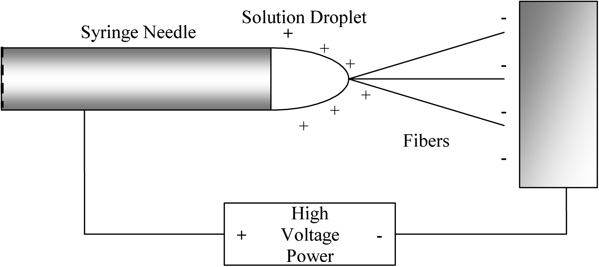
Schematic of the electrospinning needle and charge distribution. The high-voltage power supply establishes a potential between the needle and collecting plate. The charged collagen droplet experiences an attractive force from the collecting device. When the charge on the droplet builds up to a certain threshold, a stream of liquid overcomes the droplet's surface tension and flies toward the collecting device. As the fiber travels through the air, the acetic acid solvent evaporates, so the fibers are dry when they land on the collecting device. Note: not drawn to scale.
The electrospinning solution was prepared by mixing collagen (type I acid soluble from calf skin; Elastin Products, Owensville, MO) in acetic acid (>99%; EMD, San Diego, CA). The solution concentrations were varied from 4 to 7.5 wt% collagen to find the optimal solution concentration for electrospinning small-diameter fibers. The solution was heated to 35°C for 10 min and left to stir overnight to ensure that the collagen was completely dissolved and had cooled to room temperature. The solution was loaded into a syringe (Air-tite Products, Virginia Beach, VA) with a blunt-ended needle (18, 20, or 22 gauge). The syringe was then placed on a syringe pump (KD Scientific, New Hope, PA) and directed toward a grounded collection device. Voltages of 4.0–9.0 kV were applied to the needle when the flow rate on the syringe pump was set to dispense at 0.05–0.30 mL/h. Randomly oriented fibers were constructed by electrospinning onto 15-mm round glass cover slips attached to a grounded square copper plate. Uniformly aligned fibers were constructed by electrospinning onto either a rotating mandrel or a dual plate device. The rotating mandrel consisted of a copper tube (diameter, 0.5′′ [1.27 cm]; length, 10′′ [25.4 cm]) attached to insulated bearings and a steel frame. The mandrel was rotated with a 6–10 V DC rotating motor (Herbach and Rademan, Moorestown, NJ) and translated horizontally (Unislide motor; Velmex, Bloomfield, NY) With this setup, rotation speeds up to 5600 rpm were achieved, as measured by a Circuitmate Universal Counter UC10 that was calibrated with an optical device. Fibers were removed from the mandrel by peeling them off in 1.25-cm-wide strips along the tube circumference. Dual plate devices used in these experiments consisted of two 2.5 × 0.5 cm copper strips attached to a gap substrate with Gluseal (Glustitch, Gulf Road Point Roberts, WA). We investigated three gap substrates: regular grade glass, quartz glass (McMaster-Carr, Elmhurst, IL), and chlorosulfonated polyethylene (CSM) (McMaster-Carr). According to Li et al. the electrical resistivity of the gap substrate has an observable affect on fiber alignment. Resistivity values for our substrates were estimated with CES selector 4.5 (Granita Design Limited, Cambridge, United Kingdom): quartz (1020 Ωm) and CSM (1017 Ωm). The electrical resistivity of glass is typically around 1012 Ωm. 29 The gap between the copper strips was varied (0.5, 1, and 1.5 cm), and each copper strip had a separate grounding wire. The copper plates were removed before crosslinking and cell culture.
The relationship between solution concentration and needle gauge and fiber diameter was determined by electrospinning three samples per solution concentration and three samples per needle gauge, and then measuring the diameter of up to 30 randomly chosen fibers with the scanning electron microscopy (SEM). The area over which fibers were counted was standardized between all samples. The degree of fiber alignment was determined by measuring the angle between 45 randomly chosen fibers and a randomly chosen axis on SEM images and calculating average angle and standard deviation for each sample. To compare fiber alignment between samples, the standard deviation from the axis of fiber alignment was compared. Samples with a greater standard deviation were less aligned than samples with a smaller standard deviation. Statistical significance between data from different sample sets was determined with an ANOVA general linear model using Minitab 15 (Minitab, State College, PA).
Scanning electron microscopy
Wet samples were prepared for SEM by standard methods. 34 Briefly, samples are fixed over night in 10% neutral-buffered formalin and further fixed in 2.5% glutaraldehyde for 1 h. Samples were then postfixed in 0.5% osmium tetroxide and dehydrated in increasing concentrations of ethanol. Finally, the samples were dried overnight in hexamethyldisilazane. 35 Before imaging, samples were mounted on SEM stubs and sputter coated (Cressington 108 Auto) at 10 mA for 90 s. Samples were imaged and fiber diameters were measured using a Zeiss LEO 982 field emission scanning electron microscope with 5 kV of acceleration voltage (Pomona College, Claremont, CA).
Crosslinking the electrospun fibers for cell culture
A variety of crosslinking methods were compared to determine an optimal procedure for cell culture studies. Liquid glutaraldehyde crosslinking involved soaking the samples in 0.1% glutaraldehyde for 1 h. The glutaraldehyde was removed from the fiber mats with 0.2 M ethanolamine solution to ensure removal of excess glutaraldehyde. Under sterile conditions the samples were transferred to culture dishes and rinsed four times with milli Q water and once with phosphate-buffered saline. The vapor glutaraldehyde treatment involved locking the samples in a desiccator for 1 and 3 days with 10 mL of 25% glutaraldehyde solution. Dehydrothermal (DHT) crosslinking involved placing the fiber samples in a vacuum oven at 110°C and 30 atm for 1 and 3 days. Fibers were subjected to the following conditions: (i) 0.1% glutaraldehyde solution for 1 h, (ii) DHT for 1 day, (iii) DHT for 3 days, (iv) 25% glutaraldehyde vapor for 1 day, (v) 25% glutaraldehyde vapor for 3 days, (vi) DHT for 1 day and 0.1% glutaraldehyde solution, (vii) DHT for 3 days and 0.1% glutaraldehyde solution, (viii) glutaraldehyde vapor for 1 day followed by 0.1% glutaraldehyde solution, and (ix) glutaraldehyde vapor for 3 days followed by 0.1% glutaraldehyde solution. After each treatment the fibers were soaked in water at 37°C and 5% carbon dioxide for 24 h to simulate typical cell culture conditions, and then imaged in the SEM to observe fiber integrity.
Culture methods for characterizing the effect of electrospun scaffolds on RCF behavior
After fibers were sufficiently crosslinked, they were sterilized with four water rinses over the course of 1–2 days in a tissue culture hood under UV light. RCFs were seeded on the aligned scaffolds in six-well tissue culture plates at a density of 50 cells/mm2 in 4 mL of medium solution. Cells were seeded on unaligned scaffolds in 12-well tissue culture plates at a density of 50 cells/mm2 in 1.7 mL of medium solution. The medium used in these experiments was corneal fibroblast cell growth medium (Ham's nutrient mixture F-12 [Dulbecco's modified Eagle's medium–F-12; Sigma, St. Louis, MO], 10% fetal bovine serum [FBS; Sigma], and 1% antibiotic–antimycotic [500 units penicillin, 0.5 μg streptomycin, and 1.25 μg amphotericin B; JR Scientific, Woodland, CA]). The medium was changed every 2–3 days for 7 days.
Observing and quantifying RCF protein expression with immunofluorescence
Samples were fixed in 4% paraformaldehyde and permeabilized with 0.1% Triton-X (Sigma). Samples were labeled with a nuclear stain (Sytox Green; Invitrogen, Grand Island, NY), monoclonal anti-human α-SMA, mouse IgG2a isotype (Sigma), and monoclonal anticollagen type I, mouse IgG1 isotype (Sigma). The secondary antibody for the α-SMA was Rhodamine-conjugated goat anti-mouse IgG subclass 2a (Jackson Immuno Research, West Grove, PA), and for the collagen type I was Cy5-conjugated goat anti-mouse IgG subclass 1 (Jackson Immuno Research). Samples were imaged with a Zeiss 510 confocal microscope (Harvey Mudd College, Claremont, CA). Levels of cellular α-SMA expression were quantified on images of four arbitrarily chosen locations on each sample. There were three samples for each culture condition for a total of 12 images per condition. In each image the ratio of cells expressing α-SMA to total number of cells was calculated by three independent individuals. Using Minitab (Minitab), an ANOVA general linear model was used to determine the statistical significance of the data.
Results
Effect of solution concentration
To spin nonbeaded continuous fibers, a small, stable solution droplet was needed at the tip of the needle. This was achieved with a syringe pump flow rate ranging from 0.2 to 0.4 mL/h. SEM images revealed that solution concentration is a significant variable for governing fiber diameter (Fig. 2). Other electrospinning variables such as voltage and flow speed were not determining factors of fiber size, but they were crucial for sustaining a droplet at the end of the needle. The voltage was adjusted so that the droplet at the end of the needle would not sputter, and the flow rate was adjusted to maintain a stable droplet. When electrospinning collagen solutions, there was a small range of voltages and flow rates that resulted in a stable droplet. For each solution concentration there was an optimum voltage range from 4.0 to 6.0 kV, and anything above or below resulted in sputtering. Different voltages had a statistically insignificant effect on fiber diameter (data not shown). Different solution concentrations produced statistically significant differences in fiber diameter of the electrospun mats with p-values of less than 0.01 (Fig. 2). The 7.5% solution produced an average fiber diameter of 440 nm ± 70 nm, the 5% solution produced fibers with an average diameter of 200 nm ± 40 nm, and the 4% solution produced fibers with an average diameter of 40 nm ± 8 nm (Fig. 2). We observed that fiber size was less variable in lower concentration solutions.
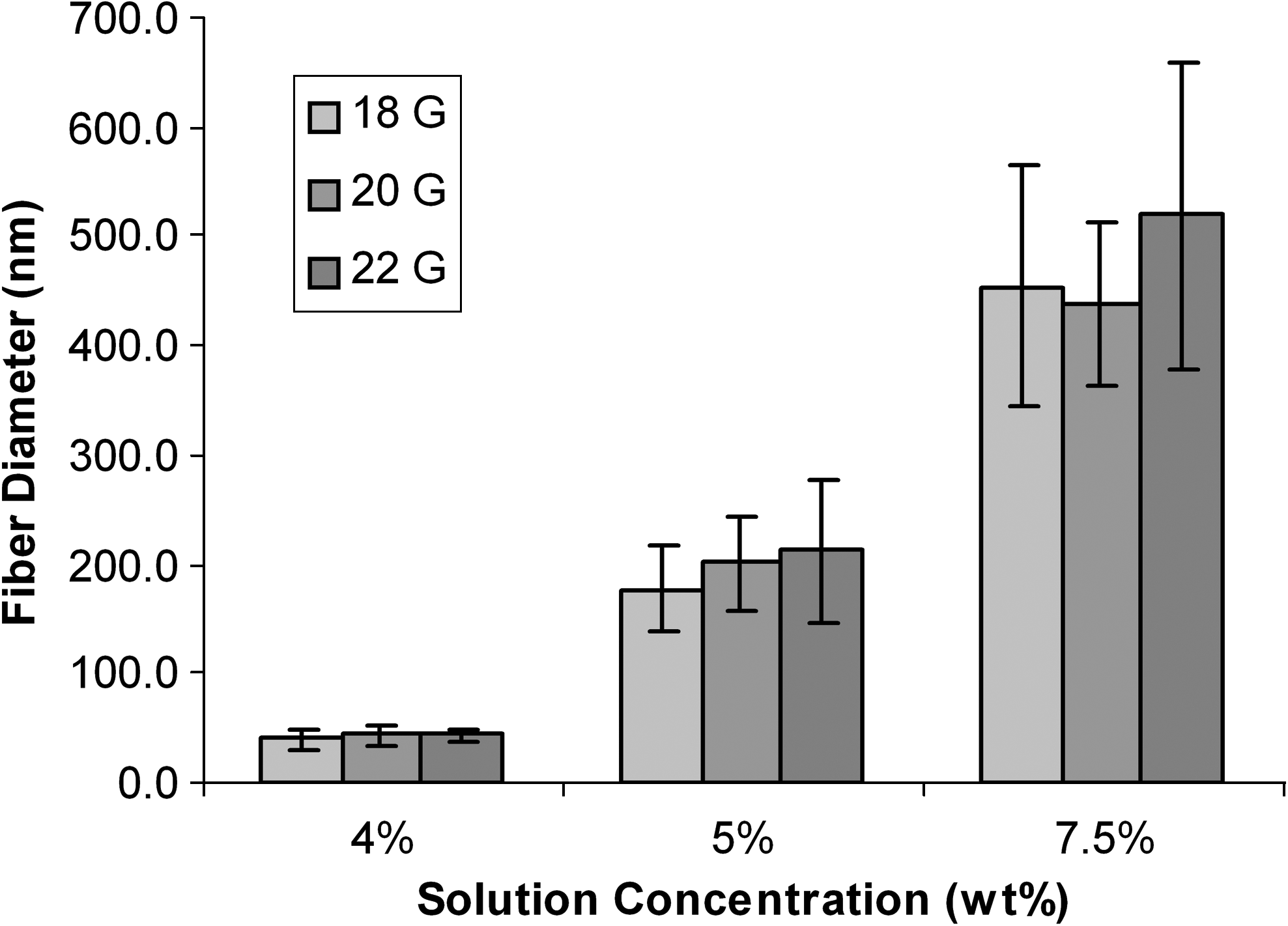
The effect of solution concentration and needle gauge on fiber diameter. Lower solution concentrations produced smaller fibers, while higher solution concentrations produced thicker fibers with a 20-gauge needle. The 7.5% solution produced an average fiber diameter of 440 nm ± 70 nm, the 5% solution produced fibers with an average diameter of 200 nm ± 40 nm, and the 4% solution produced fibers with an average diameter of 40 nm ± 8 nm. The difference between fiber diameters from each of the solution concentrations was statistically different (p < 0.01.) The needle gauge had an insignificant effect on fiber diameter at the 4% solution concentration. The needle gauge caused slight variability in the 5% and 7.5% solutions but was statistically insignificant (p > 0.05 for all conditions).
Effect of needle gauge on fiber morphology
The relationship between syringe needle gauge and fiber diameter was determined by electrospinning 4, 5, and 7.5 wt% collagen solutions with 18-, 20-, and 22-gauge needles. The average fiber diameter on each sample was determined by measuring up to 30 randomly chosen fibers with the SEM (Fig. 2). Needle gauge had no significant effect on fiber diameter for solution concentrations of 4%, 5%, or 7.5%. The 4 wt% concentration solutions produced fibers with consistent diameters of about 40 nm regardless of the needle gauge (Fig. 2). In addition, needle gauge did not have an effect on the uniformity of fiber diameter or on fiber morphology, including beading.
Electrospinning aligned fibers
To electrospin aligned collagen type I fibers, two collection methods were investigated: the rotating mandrel and dual plate electrode methods. Fibers were electrospun onto the mandrel when it was rotating at specific speeds ranging from 720 to 5805 rpm. The analysis of angle deviation for 45 randomly selected fibers from SEM images revealed that the most aligned fibers were collected on the mandrel spinning at 5300 rpm with a standard deviation of 27° (Fig. 3B). The least aligned fibers were collected on the mandrel spinning at 1215 rpm with a standard deviation of 60° (Fig. 3A). Although it appeared that the fibers became more aligned with an increase in rotating speed (p < 0.01 between fibers spun with 5300 and 1215 rpm), uniformly aligned fibers were not achieved with the rotating mandrel method.

Electrospun fibers collected on a mandrel device rotating at (
The dual plate collection device collected fibers that were more aligned than fibers collected on the rotating mandrel with a standard deviation of 8° (p < 0.01) (Fig. 4B). Certain variables were explored to optimize the fiber orientation using this design. SEM images revealed that there were higher levels of orientation and fiber deposition when the dual plates were 2.5–4 cm away from the needle tip. At distances further than 4 cm, there was less orientation and less fiber deposition. When the dual plates were less than 2.5 cm away from the needle tip, fiber deposition was concentrated in the area directly in front of the needle. The width of the dual plates also had a noticeable effect on the fiber orientation. More fibers aligned with the narrow plates (0.5 cm width) than with the wider plates (1.5 cm width). The gap distance between the dual plates also had an affect on fiber alignment. Confluent and uniformly aligned fibers were collected when the distance between the plates was 0.5 cm. Fewer fibers collected in the gap and the alignment was less confluent when the distance was 1 or 1.5 cm (data not shown).

The dual plate glass substrate had an observable effect on fiber alignment. Substrates with higher electrical resistivity properties correlated with more uniformly aligned fibers collected in the gap region. (
Effect of dual plate gap substrate on fiber alignment
The substrate material for collection of fibers between the dual plates altered fiber alignment. When the dual plates lacked a gap substrate, the fibers did not align and were difficult to collect for crosslinking and cell culture processes. When the gap substrate was glass, uniformly aligned fibers collected between the dual plates (Fig. 4A). When a gap substrate with a higher electrical resistivity, such as quartz glass or CSM, was used, an increase in alignment was observed (Fig. 4B, C).
Crosslinking electrospun fibers
Several crosslinking methods were investigated to find the optimal method for preserving fiber morphology during cell culture. Fibers that were not subjected to a crosslinking treatment completely dissolved in water (Fig. 5B). Similarly, fibers that were only crosslinked in 0.1% liquid glutaraldehyde dissolved completely (data not shown). Fibers that were DHT (1 and 3 days) plus liquid glutaraldehyde crosslinked did not maintain fiber morphology. Faint fiber outlines are visible in the SEM images, but for the most part fiber morphology was not maintained (Fig. 5C). Samples that were DHT crosslinked for 1 and 3 days produced the same result (data not shown). Fibers that were crosslinked in 25% glutaraldehyde vapor for 1 and 3 days appeared to have collapsed slightly (Fig. 5D, E). Fibers that were crosslinked in 25% glutaraldehyde vapor for 1 day and liquid glutaraldehyde did not retain their fiber morphology (data not shown), while 3 days of vapor plus liquid glutaraldehyde preserved fiber morphology (Fig. 5F).
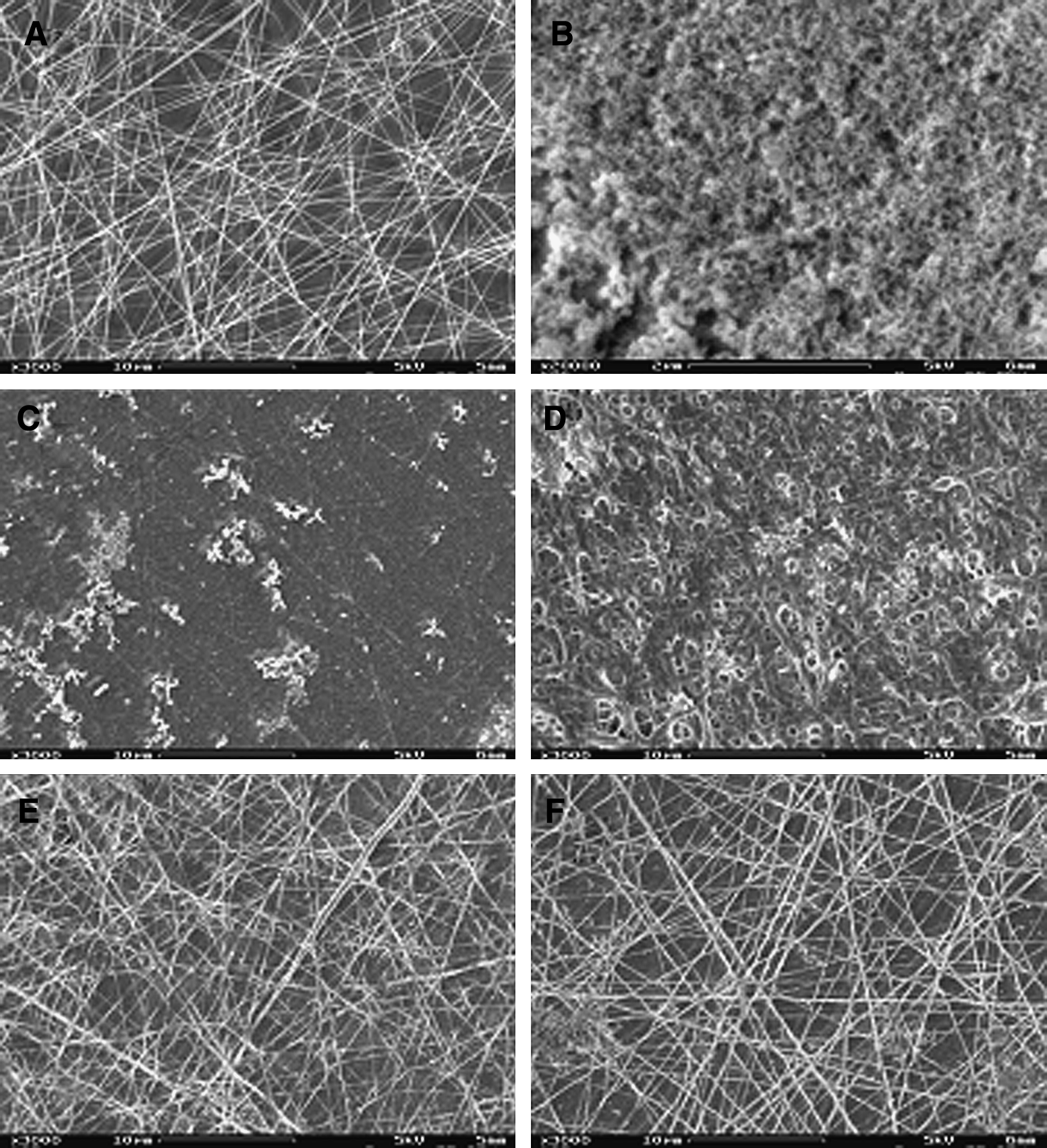
Electrospun fiber morphology after different crosslinking treatments. (
RCF behavior on aligned electrospun fibers
RCFs were grown on uniformly aligned and randomly aligned fibers for 7 days. Light microscopy revealed that after 2 days of culture, the cells on the aligned fibers began elongating along the direction of fiber alignment, while cells on the unaligned fibers were randomly oriented (Fig. 6, top). At day 7, the cells were sacrificed for SEM and immunofluorescence imaging. SEM images confirmed the light microscope observations; the morphology of the cells on the randomly aligned scaffold resembled cells grown in a tissue culture dish, while the morphology of cells on the aligned scaffold was long and stretched along the direction of fiber alignment (Fig. 6, middle). Immunofluorescence images revealed that cells cultured on randomly oriented fibers exhibited a similar level of α-SMA protein expression like fibers cultured on a tissue culture dish. However, fibroblasts cultured on aligned fibers expressed less α-SMA (Fig. 6, bottom). A quantitative assessment of the immunofluorescence (IF) images revealed that the aligned fibers supported a significantly lower percentage of RCFs expressing α-SMA than the unaligned fibers or tissue culture dishes (p < 0.01). About 14% of the RCFs on aligned fibers expressed α-SMA, while 34% of RCFs expressed α-SMA on randomly aligned fibers, and 42% of RCFs expressed α-SMA in tissue culture dishes (Fig. 7). There was no difference between α-SMA expression between the no-scaffold and unaligned samples (p = 0.72).
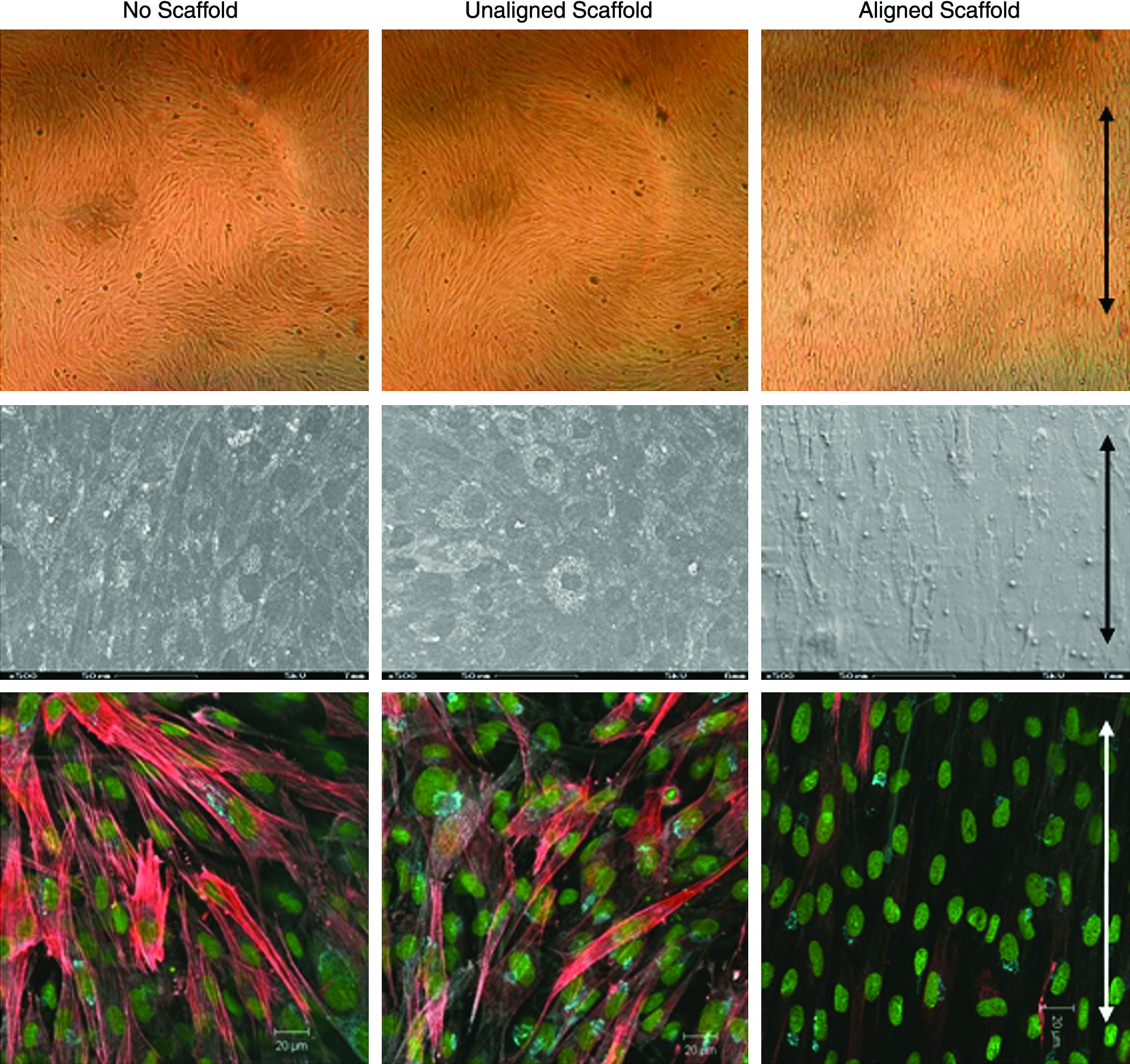
RCFs grown on aligned fibers expressed different amounts α-SMA than RCFs grown on unaligned fibers and tissue culture dishes. Top row: light microscopy images of RCFs cultured on tissue culture plates, and on unaligned and aligned electrospun fibrous scaffolds. Middle row: SEM images revealing the morphology of the RCFs grown on the various substrates. Bottom row: IF images of RCFs on the various substrates. Cell nuclei are green; α-SMA is stained red. Arrows indicate the direction of fiber alignment. Color images available online at www.liebertonline.com/ten.
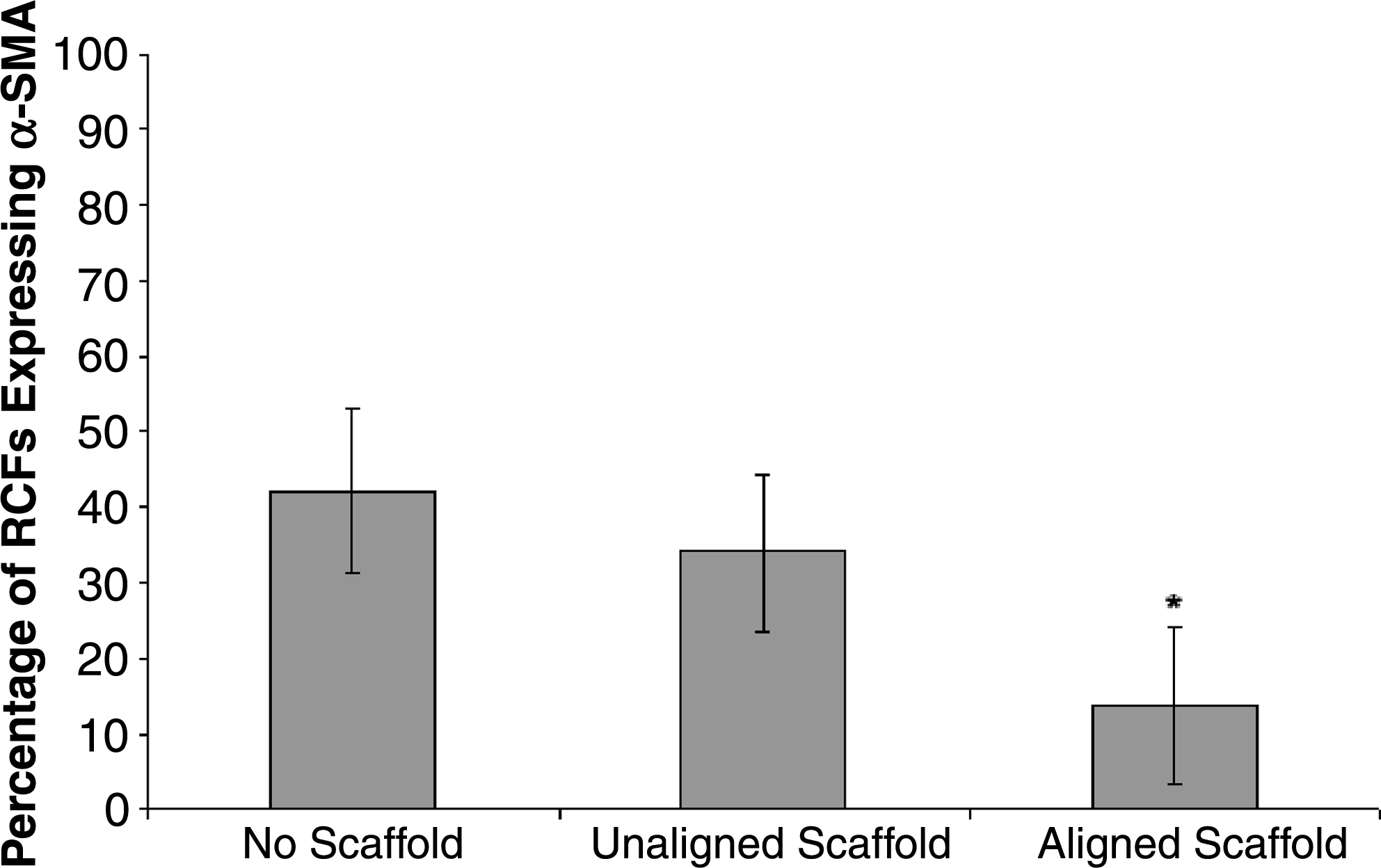
Percentage of RCFs expressing α-SMA as determined from confocal immunofluorescence. The no-scaffold and unaligned scaffold samples had a similar percentage of cells expressing α-SMA. The aligned scaffolds have a statistically significantly lower percentage of cells expressing α-SMA (*indicates p < 0.01) than the unaligned and no-scaffold cells.
Discussion
Electrospinning small-diameter, aligned collagen fibers
In this study we have successfully electrospun a scaffolding material composed of small-diameter, aligned collagen fibers approximately 30–50 nm in diameter using an optimized dual plate collection method. We report that our collagen type I can be dissolved in acetic acid and electrospun without adding synthetic polymers or toxic solvents. Type I collagen fibers have been successfully electrospun for a variety of applications. Other investigators, including Shih et al., Zhong et al., and Matthews et al., have electrospun collagen by dissolving it in HFP.20,21,25 However, this chemical is particularly toxic and difficult to work with, and raises issues of cytocompatibility in the produced fibrous mats. Some investigators have used acetic acid solutions to dissolve collagen type I, but to spin unbeaded, continuous fibers they had to add PEO, which acts to stabilize the polymer solution.23,26
In addition, we have electrospun small-diameter (40 nm ±8 nm) collagen fibers with very uniform fiber diameter. Several groups have achieved large-diameter type I collagen fibers electrospun in HFP and hydrochloric acid.20,22,23 Some investigators spun collagen type I fibers in HFP with fiber diameters as low as 100 nm.24,25 A few studies have spun type I collagen fibers in HFP with fiber diameters as low as 50 nm, but their samples were not uniform and also contained larger fibers up to 200–300 nm.20,21 Huang et al. achieved nonuniform electrospun samples with fiber diameters of 50–150 nm using type I collagen mixed with PEO in acetic acid. 26
We have also created uniformly aligned small-diameter collagen fibers. In this study we compared the rotating mandrel and dual plate methods for producing aligned fibers. While other studies have found that the rotating mandrel23–25,33 produced aligned fibers, our study shows that uniformly aligned fibers were not collected. We also found that this method is not good for producing fibers for cell culture, especially if the fibers are less than 100 nm in diameter, because they are extremely delicate. Removal of the fibers from the mandrel for cell culture was difficult and destructive to the fibers. We believe that the best collection method for collecting aligned fibers for engineering artificial corneal tissue is the dual plate method. Our method for aligning the fibers was adapted from the 2003 Li et al. study. 30 The advantage of our method is that it is more robust and has broader applicability to other TE systems. Our adaptation allows spinning of aligned fibers and preparing them for cell culture without extensive handling. After the fibers are collected on the gap substrate, the copper plates are removed by making a small incision on either side of the gap and thereby avoiding displacement of the fibers in the gap region and allowing for cell culture directly on the substrate material coated with fibers. We found increased alignment with high electrical resistivity gap substrates, such as quartz and CSM polymer, which is consistent with published results on electrospinning with PVP. 29 When regular-grade glass of lower electrical resistivity was used (i.e., a traditional cover slip), we observed a decrease in fiber alignment. To improve our optimized method we will need to be able to collect aligned fibers over a larger gap width. Currently, the gap width is 0.5 cm, but to make a viable corneal replacement, this gap distance needs to be closer to 2.5 cm.
Achievement of small-diameter, aligned collagen fibers is an important first step in creating a functional substrate for a TE cornea. This method can be built upon to incorporate collagen types V and VI and important proteoglycans that are known to be present in the native cornea. The present single-layer constructs are optically transparent, but are only 20–50 μm in thickness. The next step is to build the aligned fibers into a three-dimensional scaffold that replicates the natural arrangement of fibers in the cornea. We plan to achieve this by rotating the dual plates during electrospinning to obtain distinct layers of aligned fibers. Another option is to grow the cells on a monolayer of fibers and then stack multiple cell-seeded monolayers into one construct.
Preparing fibers for cell culture
We found that the best method for crosslinking our fibers was to sequentially expose the fibers to glutaraldehyde vapor followed by glutaraldehyde liquid submersion. In the literature there are a variety of protocols for crosslinking with glutaraldehyde vapor,21,22,24 but our study found that the optimal crosslinking was achieved with 25% glutaraldehyde vapor crosslinking for 3 days plus submerging the fibers for 1 h in 0.1% liquid glutaraldehyde. The other studies that employed vapor crosslinking did not supplement their procedure with liquid glutaraldehyde. Our group decided to use this step to further crosslink and sterilize the fibrous samples. After removal of the glutaraldehyde, the crosslinked fibers were not toxic to the cells, which indicates that our crosslinking protocol is a consistently viable method for preserving fiber morphology for cell culture.
Controlling cell behavior
Our results indicate that electrospun fibers support cellular growth and that uniformly aligned fibers cause RCFs to elongate along the axis of fiber alignment. The RCFs on randomly aligned fibers did not have a preferred direction of alignment. This result indicates that cells are able to respond to changes in microstructure and organization of the ECM environment at the tens of nanometers scale. Other sources have reported similar cell responses to aligned substrates.21,22,36 Xu et al. cultured smooth muscle cells on 200–800-nm aligned fibers, Casper et al. grew osteoblast-like cells on 3000–6000-nm aligned fibers, and Zhong et al. seeded rabbit conjunctiva cells onto aligned fibers ranging in diameter from 50 to 300 nm. These studies reported that all of these cell types aligned themselves along the direction of fiber alignment. One study tested the effect of substrate microstructure on human keratocyte behavior by culturing the cells on silicon oxide–coated wafers that had been etched with parallel ridges. 37 The study suggested that keratocyte morphology can be controlled by the nanostructure of the cell culture substrate, and reported that keratocytes aligned more strongly on substrates with 800-nm or larger ridge separations than on substrates with 400-nm ridge separation, and that intracellular stress fibers (actin) were less evident on 400-nm separation substrates. Our results suggest that corneal fibroblasts respond to substrates with fiber diameters as small as 40 nm by aligning in the direction of the fiber orientation. The differences in the results may be due to the different materials used: cells on our substrates may be responding to the combined effects of collagen and alignment.
Our results also show that aligned collagen fibers act as a signaling mechanism for downregulating α-SMA expression in the RCF population. This is a promising result because it shows that we may be able to control the phenotype of corneal cells in the TE environment. The ability to downregulate the wound-healing phenotype (characterized by α-SMA expression) should lead to improved optical properties. We may be able to build transparent artificial corneas by controlling the RCF protein expression with fiber morphology and alignment. This is the first study to show that matrix microstructure influences corneal fibroblast cell phenotype; however, other studies have shown the ability to control corneal cell phenotype with cell seeding density,38,39 soluble factors such as transforming growth factor-β6,40–43 and basic fibroblast growth factor (bFGF) and heparin,6,8 and applied stress. 44 A recent study found that corneal fibroblasts seeded on collagen matrices align along the axis of ECM stiffness and produce more collagen, which is also aligned along the axis of ECM stiffness. 44 These results suggest that mechanical signaling could induce corneal stromal cells to produce an aligned collagen matrix approximating that of the native cornea.
Conclusions
We have demonstrated in this study a method for creating uniform, small-diameter, aligned collagen matrices that can be easily transferred from the electrospinning apparatus and prepared for cell culture. In addition, we show that the ECM microstructure represents another important signaling factor for corneal fibroblast cells. Further experiments will be done with an optical coherence microscope to quantify the level of light transmittance through the aligned fibrous scaffolds. Future studies will focus on constructing thicker three-dimensional aligned scaffolds and evaluating how the cells remodel these scaffolds. Ultimately, we would like to use these scaffolds as a template for the cells to stimulate them to build thicker constructs by producing collagen fibers of the appropriate diameter and alignment.
Footnotes
Acknowledgments
The authors would like to thank the Engman Fellowship Program at Harvey Mudd College; Dr. David Tanenbaum and David Haley for assistance with the Pomona SEM; Madineh Sarvestani, Hansford Hendargo, Megan Little, and Brandon Smith for assistance in building the electrospinning setup; and Dr. Marta Bechtel for help with α-SMA quantification. Financial support for this project has been provided by the Beckman Scholars Program, Howard Hughes Medical Institute (HHMI), and NSF MRI #DBI-0420538 for the confocal microscope.
Disclosure Statement
No competing financial interests exist.