
Abstract
Synchrotron X-ray microcomputed tomography (SR microCT), with a micron resolution, was used to evaluate the osteoconduction and osteointegration by borate bioactive glass after implantation 12 weeks in a rabbit tibia model. The study focused on the biomaterial–bone interface. Results from SR microCT two-dimensional and three-dimensional (3D) reconstructions provided precise imaging of the biomaterial–bone integration and detailed microarchitecture of both the bone-like glass graft and the newly formed trabecular bone. Osteoconduction, the formation of new trabecular bone within a tibia defect, occurred only in the tibiae implanted with teicoplanin-loaded borate glass but not in those with teicoplanin-loaded CaSO4 beads, indicating the excellent biocompatibility of the glass implants. 3D reconstruction of the tibiae also showed the infiltration of vascular tissue in both the bioactive glass graft and the new trabecular bone. This study indicates that SR microCT can serve as a valuable complementary technique for imaging bone repair when using bioactive glass implants.
Introduction
Microcomputed tomography (microCT), a nondestructive technique, was first used by Feldkamp et al. to analyze trabecular bones at a spatial resolution of 50 μm. 4 So far, the technique has been used extensively in the study of trabecular bone architecture and biomaterial–bone interface.2,5–12 MicroCT provides rapid reconstruction of high-resolution 3D images, and has been used to characterize trabecular bone morphology at different sites and during aging.7,8 Recently, the technique has been used for visualization of the 3D microarchitecture of different scaffolds made from polymers, ceramics, and glasses.5,13–15 In contrast to traditional microCT, which uses a polychromatic X-ray source, synchrotron radiation microCT (SR microCT) uses a monochromatic X-ray source, which has the capacity for achieving high spatial resolution attributed to its high photon flux. Due to its accuracy and high signal-to-noise ratio, SR microCT can better determine differences in mineralization within bone.9,12,16 Further, the technique can serve as a useful tool to measure vascular ingrowth and cartilage formation within porous biomaterials. 2
Bioactive glass has been widely studied for application as a scaffold material in bone tissue engineering.17,18 Our recent work showed that the borate bioactive glass, loaded with drugs such as teicoplanin and vancomycin, could provide an effective method for treating chronic osteomyelitis and the regeneration of new bone.19–21 However, the techniques used in that work, 2D staining and radiography, provided only limited information on implant–bone interface and the distinction of newly formed bone from the host bone. Further, those techniques were limited in their ability to characterize vascular growth in the new bone and the bioactive glass graft because they lacked the requisite resolution (1–30 μm). An appropriate method to explore the 3D morphology down to about micron scale and to evaluate the osteointegration of tissue-engineered constructs is required.
The objective of the present study was to investigate the use of SR microCT for providing a 3D representation of bone induction by borate bioactive glass in a rabbit tibia model. The integration of the bioactive glass graft with the new bone and the 3D vascular tissue ingrowth within the glass were also investigated. As bioactive glasses continue to receive interest for applications in bone repair, SR microCT could serve as a useful complementary technique for evaluating the mechanisms of bone ingrowth, integration, and vascularization, which are critical in bone regeneration.
Materials and Methods
Biomaterials preparation
Borate bioactive glass with the composition (mol%): 6Na2O, 8K2O, 8MgO, 22CaO, 54B2O3, and 2P2O5 was prepared by melting analytical-grade Na2CO3, K2CO3, MgCO3, CaCO3, H3BO3, and NaH2PO4 in a Pt crucible in air for 1 h at 1100°C and quenching between cold stainless steel plates. Particles smaller than 50 μm were obtained by crushing and sieving through stainless steel sieves.
Drug-loaded pellets were prepared by mixing teicoplanin powder (Gruppo Lepetit S.p.A.), glass particles, and a solution of chitosan (98% deacetylated), citric acid, and glucose (Sinopharm Chemical Reagent Co., Ltd.). The chitosan solution was prepared by mixing chitosan, citric acid, and glucose with a weight ratio of 1:10:20. The weight ratio for the pellets containing teicoplanin powder, glass particles, and chitosan solution was 10:65:25. The mixture was filled into a polyethylene mold, allowed to harden for 30 min, and dried for 24 h. The final pellets (5 mm in diameter×3 mm in thickness) had a density of 1.5 g/cm3 with a porosity of 20%.
For the in vivo experiments, commercially available calcium sulfate beads (OsteoSet® Resorbable Mini-Bead Fast-Cure Kit; Wright Medical) were used as a comparison with the borate glass. CaSO4 beads are the most commonly used antibiotic delivery material for osteomyelitis treatment, in both experimental and clinical studies, as they can deliver local antibiotics and promote bone regeneration concurrently with their degradation.22–24 All pellets were prepared under sterile conditions, using the method described above.
In vivo study
A rabbit tibia osteomyelitis model was used in these experiments. Osteomyelitis was induced by injection of methicillin-resistant Staphylococcus aureus (MRSA) into the tibiae of pathogen-free New Zealand White rabbits, as detailed elsewhere. 19 Two groups of animals were treated by debridement and implanted with pellets containing borate glass or CaSO4 beads into the bone cavity for 12 weeks. A third group treated with debridement but without any implantation was used as control. A cortical bone window (∼2.0×0.8 mm) was made on the anteromedial surface of the proximal tibia after debridement.
After implantation, the excised tibiae specimens were harvested from the animals. Nondecalcified bone specimens, one from each group (control, borate glass, and CaSO4), were fixed in 10% formaldehyde solution for 2 weeks and used for SR microCT analysis.
SR microCT analysis
Four implants from each group were analyzed at the Advanced Light Source synchrotron radiation facility at Lawrence Berkeley National Laboratory using beamline 8.3.2. The SR microCT setup is similar to the standard setup for this technique 25 whereby samples are rotated (through a 180° angle) in a monochromatic X-ray beam of 27 KeV, which was chosen to maximize the signal-to-noise ratio, and to optimize the interaction between the X-rays and the sample. During each 180° rotation, 2D images were taken every 0.125° for the implants. The transmitted X-rays were imaged via a scintillator, magnifying lens, and a digital camera yielding an effective voxel size in the reconstructed 3D image of 4.4 μm. The samples were scanned in the absorption mode and the reconstructed images were obtained using a filtered backprojection algorithm. In this mode, the gray scale values of the reconstructed image are representative of the absorption coefficient. The data sets were reconstructed using the Octopus software and the 3D visualization was performed using Avizo® (Mercury Computer Systems, Inc.). Quantification of the reconstructed images was done using the same software.
Histological analysis
At sacrifice after 12 weeks, the excised tibia specimens were fixed in 10% formaldehyde, decalcified in EDTA, dehydrated in a graded series of ethanol, and embedded in paraffin. Sections (∼50 μm thick) in the longitudinal direction of the tibia were stained with hematoxylin and eosin (H&E) and Goldner's trichrome, and observed using transmitted light microscopy.
Statistical analysis
Each animal experimental group contained at least four replicas. The data are presented as the mean standard deviation. Statistical analysis was performed with one-way analysis of variance followed by a Tukey's post hoc test, with the level of significance set at p<0.05.
Results
Visual observation
In tibiae without any implants (control) or implanted with teicoplanin-loaded CaSO4, a large cavity created by osteomyelitis after MRSA injection and debridement was observed after 12 weeks (Fig. 1a, b). No filling materials were found in the group implanted with CaSO4, an indication of the total dissolution of CaSO4 beads, as noted in previous reports.21–24 On the other hand, new bone formation was observed in the tibia implanted with teicoplanin-loaded borate glass (Fig. 1c), and the cavity was complete filled. Good integration was observed between the glass graft and the surrounding bone.
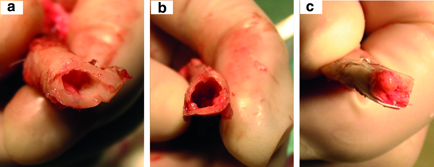
Optical image of the tibia postharvesting:
SR microCT analysis
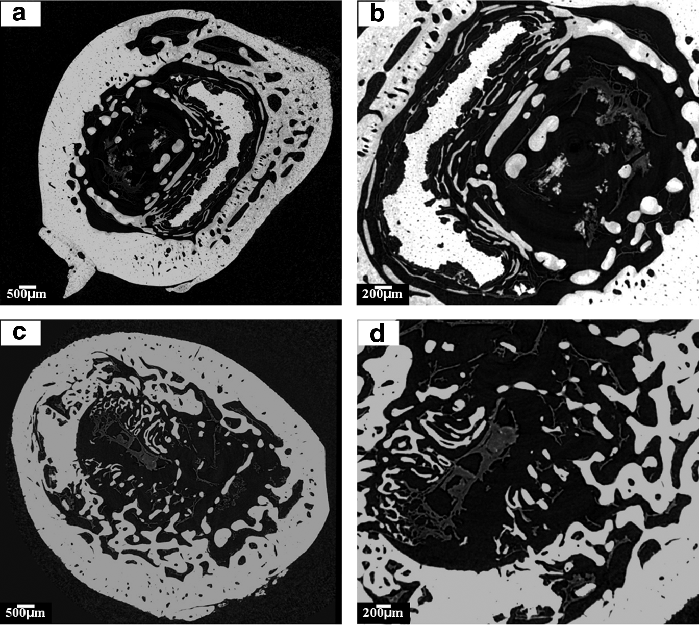
Figures 2 and 3 show the 2D SR microCT reconstructed sections of harvested tibiae with no implant (Fig. 2a, b) and implanted with teicoplanin-loaded CaSO4 beads (Fig. 2c, d) or with teicoplanin-loaded borate glass (Fig. 3a, b). Regions with different colors were observed in the sections: black, gray, and white in Figure 2; black, dark gray, light gray, and white in Figure 3.
Two-dimensional reconstructed section of a tibia defect
As the synchrotron radiation is monochromatic, the gray level intensities (X-ray attenuation coefficients) of the 2D sections are used to quantify the material radio opacity, which is proportional to the concentration of the local mineral in bone. This enables the delineation of low- and high-mineralized bone. The mature lamellar bone typically has substantially higher density than newly mineralized bone, resulting in brighter color.9,12,16 In this study, the host bone has the highest density and the brightest color, corresponding to white areas; the newly formed bone and bone-like glass graft has the medium density and a light gray area; the vascular tissue has a low density and a corresponding dark gray area; and the proteins and soft tissues have the lowest density and a corresponding black color, which means there is no X-ray absorption.
For tibiae without any implants, a large cavity was observed in the center (Fig. 2a) and only host bone (in white) infiltrated with vascular tissues (in dark gray, Fig. 2b) were present. For the tibiae implanted with teicoplanin-loaded CaSO4, a similar cavity in the center was observed without new bone formation. Based on the 2D reconstructed section, no other mineral phases other than bone were detected, an indication of the total dissolution of the CaSO4 beads in vivo. Small cavities inside the cortical bone were observed, which were attributed to the formation of osteoplasts (osteocyte lacunae).
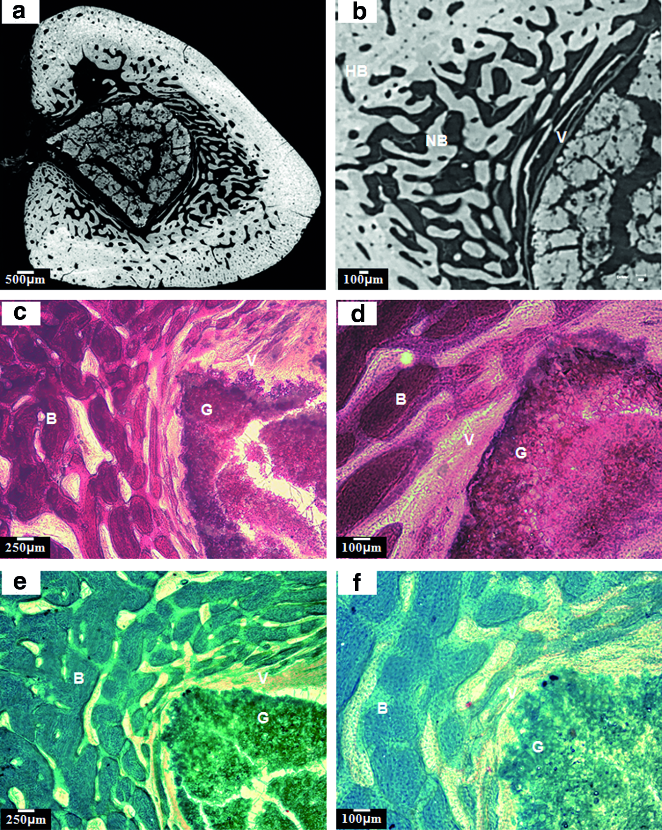
In contrast, for the tibiae implanted with teicoplanin-loaded borate glass, areas with light gray colors were observed in addition to the white (host bone), dark gray (vascular tissue), and black areas (protein and soft tissue) (Fig. 3a, b). Based on the H&E (Fig. 3c, d) and Goldner's trichrome (Fig. 3e, f) staining results, the light gray in the center of the tibia corresponded to the bone-like grafts converted from borate glass (Fig. 3a), whereas the area adjacent to the white area corresponded to the newly formed trabecular bone (Fig. 3b). The morphology of the new bone had a sponge-like structure, similar to human trabecular bone, whereas the bone-like glass grafts contained micropores. Vascular tissue was observed to be distributed in both the new bone and the glass graft (Fig. 3b), which were in good agreement with the results from staining sections (Fig. 3c–f). The cracks in the graft probably resulted from the drying of the tibia.
3D reconstruction of the implants
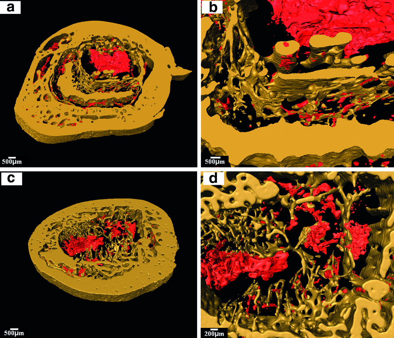
As described previously, 3D representations of the tibiae were reconstructed using Avizo software. The different areas present in the 2D sections were differentiated into separate phases and visualized using the software. Representations of tibiae without implant or implanted with CaSO4 beads are shown in Figure 4. The images show the bone structure with a dense cortical bone shell (yellow) and porous trabecular bone (yellow) infiltrated with vascular tissues (red). A large cavity remained in the center of the tibiae in both groups due to the bone infection and debridement induced by MRSA injection. Only vascular tissues were observed in the center with the absence of mineral tissues (Fig. 4b, d).
Three-dimensional reconstructed blocks of a tibia defect
Figure 5 shows a tibia implanted with borate glass. Good integration between the glass graft (blue), new bone (gray), and host bone (yellow) is observed. The glass graft was infiltrated with a vast amount of vascular tissues (red, Fig. 5b) and was in close contact with the newly formed trabecular bone (Fig. 5c). The infiltration of vascular tissue in the newly formed bone was also readily observed (Fig. 5d). A gross view of the bone and implants of the same tibia is shown in Figure 6. A detailed architecture of the newly formed trabecular bone and converted glass implants is also reconstructed (Fig. 6c, d). Micro pores of 5–10 μm were widely observed in the glass graft, resulting from the glass conversion.
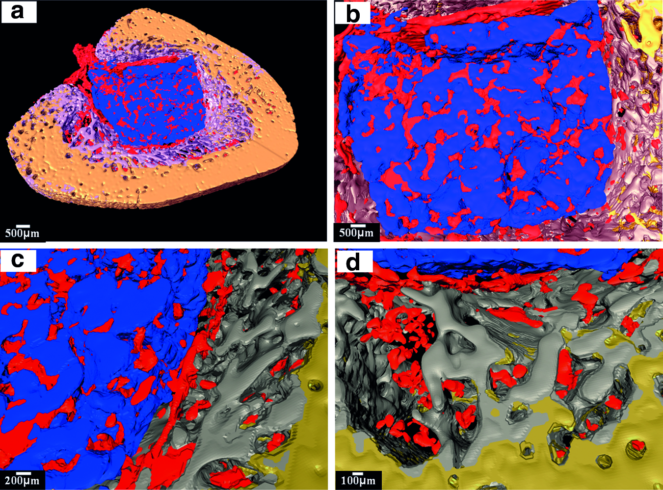
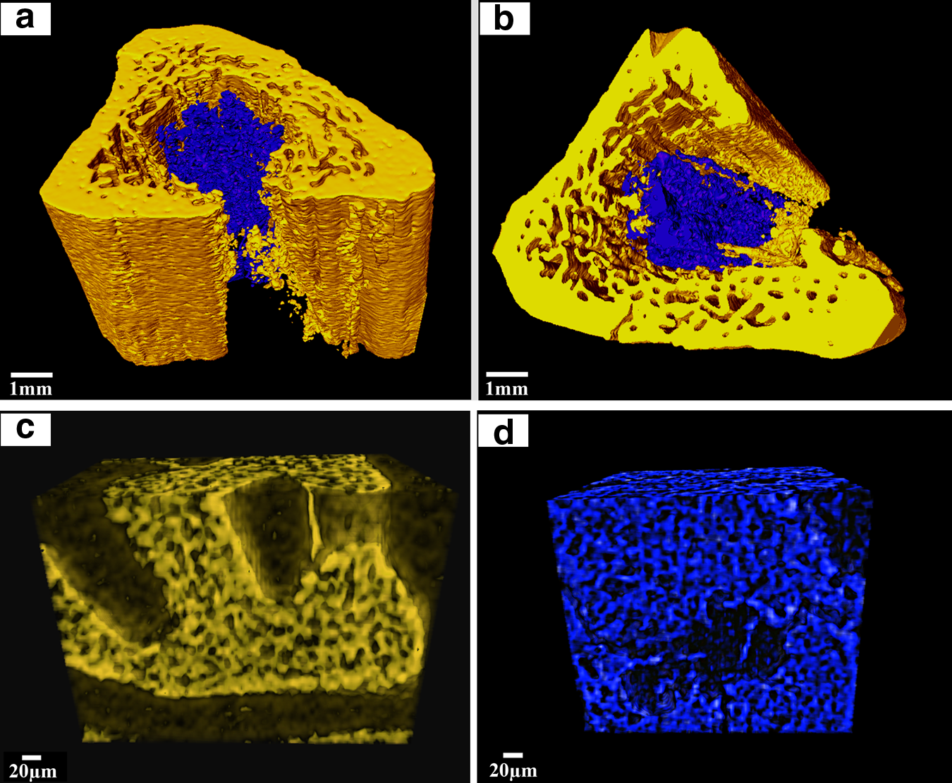
Table 1 shows the quantification of the percentage of new bone formed within the tibia. Teicoplanin-loaded borate glass implant achieved a significantly better bone healing with 32% of bone (old and new bone) formation in the tibia, whereas teicoplanin-loaded CaSO4 and control only had 13%±3% and 10%±5% of old bone, respectively. When implanted with the borate bioactive glass implant, the defect in the tibia was almost completely filled, which was in good agreement with the observations in Figures 1 and 6.
Discussion
In previous studies, vancomycin- or teicoplanin-loaded borate glasses were reported to be effective in treating chronic osteomyelitis induced by the injection of MRSA in a rabbit tibia model.19–21 The cure was attributed to the combination of sustained drug release and the new bone regeneration induced by the implanted bioactive glasses. However, there were no detailed investigations of the biomaterial–bone interface in these studies and the mechanisms for the new bone formation. In this work, SR microCT was used to study the osteoconduction and osteointegration of the borate bioactive glass implant and to provide 3D imaging representation of microarchitecture.
The utility of SR microCT in the study of biomaterial–bone reaction is first demonstrated by its ability to distinguish the differences between new bone, host bone, vascular tissue, and bone-like glass graft, as shown in 2D reconstructed sections (Figs. 2 and 3). No bone formation was found in the tibiae without implants or implanted with CaSO4 beads, whereas a vast amount of new bone formed in the tibiae implanted with borate glass. These findings correspond well with the gross view of the harvested implants (Fig. 1). There were also good correlations between the SR microCT (Fig. 3a, b) and histomorphometric 2D sections (Fig. 3c–f): (1) vascular tissue infiltration in both trabecular bone and bone-like graft; (2) the presence of micropores within the bone-like grafts; and (3) integration between trabecular bone and graft.19,20 In addition to these findings, SR microCT provides more detailed information on the interpretation of the implants. First of all, the technique enables the distinction between the new bone and host bone. In the tibiae implanted with borate glass, new trabecular bone was formed adjacent to the host trabecular and cortical bone (Fig. 3b), an indication of the osteoconduction by the borate glass. However, the newly formed trabecular bone was assigned to host bone in the previous work due to the insufficient information obtained from the staining slides.19,20 Second, the morphological information obtained from SR microCT provides clearer determination of the bone-like graft formed by the conversion of the borate glass, which could not be easily discerned based on the staining sections alone.19,20
The 3D architecture of the tibia was reconstructed based on the SR microCT sections (Figs. 4–6). The 3D reconstructed images clearly show the typical trabecular and cortical bone structure with the trabecular bone consisting of a porous network of rod- and plate-like trabeculae, and cortical bone being much denser. Further, this study indicates that osteoconduction occurred only in the presence of borate glass (Fig. 5), whereas no obvious new bone formed in the tibiae implanted with CaSO4 beads. New bone was formed in the peripheral area of the old trabecular and cortical bone, grew inside the tibia, and integrated well with the glass graft.
Although there is no general agreement on the mechanism of osteoconduction by calcium phosphate biomaterials, several factors, including the geometry, surface chemistry, and porous structures, are reported to play important roles.26–29 In the present work, two factors are probably attributable to the osteoconduction by the borate glass: the porous network consisting of hydroxyapatite (HA)-type materials and the ions released during the glass conversion. Borate glass converts rapidly and completely to HA-type materials both in vitro and in vivo.19–21,30–32 The converted HA-type material forms a porous network, which is an important requirement for scaffolds capable of supporting nutrient delivery and new bone ingrowth. This also promotes the ingrowth of vascular tissue into the material as shown in Figure 3. Moreover, the formation of bone-like HA enhances the ability of the material to support the new bone formation. 27 The in vivo dissolution of the borate glass, as evidenced by the micro pores in Figure 6d, leads to the release of K+, Na+, and Ca2+ ions, which are present naturally in the body and reported to activate expression of osteogenic genes32,33 and to stimulate angiogenesis.34–36 These released ions are also considered to induce new bone formation.
Also of note in this work is that the 3D visualization of the vascular tissue in both the glass graft and the trabecular bone is achieved without using any perfused contrast agent (Figs. 4 and 5), which is of tremendous value for the regeneration of vascularized tissue such as bone and muscle. 2 In the previous microCT studies, vascular ingrowth into porous scaffolds has to be evaluated postmortem using a perfused contrast agent that polymerizes within the vessels, creating a stable radiodense cast. 37 The samples also have to be demineralized before microCT scanning to facilitate segmentation of the vascular structures, which prevents the visualization of the vascularization in the scaffolds and new bone. Although the technique provides good visualization of the vascular tissue, there are difficulties in controlling the perfusion: incomplete perfusion will lead to insufficient visual inspection, whereas perfusion at high pressure leads to the generation of large bulbous artifacts. 2 The success of visualizing the vascular tissue, scaffold, and bone in the present work is attributed to the high spatial resolution due to its high photon flux and signal-to-noise ratio of the SR microCT.9,12,16
Conclusion
SR microCT allows an evaluation of the different phases (host bone, new bone, bone-like graft, and vascular tissue) present in the tibiae of rabbits with a micron resolution. The 2D and 3D reconstructions provide precise imaging of the biomaterial–tissue reaction and detailed microarchitecture of both the biomaterials and the newly formed trabecular bone. The results obtained in this study are in good agreement with the 2D histological analysis of stained sections and validate the use of the technique. Osteoconduction occurred only in the tibiae implanted with teicoplanin-loaded borate glass, and not in the tibiae implanted with teicoplanin-loaded CaSO4 beads, showing the excellent biocompatibility of the glass implants. Observations of the 3D SR microCT reconstruction showed the infiltration of vascular tissue in both the bone-like graft formed by conversion of the borate glass implant and in the new bone. This study indicates that SR microCT can serve as a valuable technique for investigating the biomaterial–bone interface and quantification of the tissues formed within the implants.
Footnotes
Acknowledgments
This work was supported by the National Institutes of Health/National Institute of Dental and Craniofacial Research Grant No. 1 R01 DE015633; the Shanghai Committee of Science and Technology of China through the major project Grant No. 084411900500 and for special projects of nanotechnology Grant No. 0952nm03400; and the NNFC of China Grant No. 51072133. We acknowledge support from the dedicated X-ray tomography beamline 8.3.2 at the Advanced Light Source, funded by Department of Energy under Contract No. DE-AC02-05CH11231.
Disclosure Statement
No competing financial interests exist.