
Abstract
Fibrin–polyurethane composite scaffolds support chondrogenesis of human mesenchymal stem cells (hMSCs) derived from bone marrow and due to their robust mechanical properties allow mechanical loading in dynamic bioreactors, which has been shown to increase the chondrogenic differentiation of MSCs through the transforming growth factor beta pathway. The aim of this study was to use the finite element method, mechanical testing, and dynamic in vitro cell culture experiments on hMSC-enriched fibrin–polyurethane composite scaffolds to quantitatively decipher the mechanoregulation of chondrogenesis within these constructs. The study identified compressive principal strains as the key regulator of chondrogenesis in the constructs. Although dynamic uniaxial compression did not induce chondrogenesis, multiaxial loading by combined application of dynamic compression and interfacial shear induced significant chondrogenesis at locations where all the three principal strains were compressive and had a minimum magnitude of 10%. In contrast, no direct correlation was identified between the level of pore fluid velocity and chondrogenesis. Due to the high permeability of the constructs, the pore fluid pressures could not be increased sufficiently by mechanical loading, and instead, chondrogenesis was induced by triaxial compressive deformations of the matrix with a minimum magnitude of 10%. Thus, it can be concluded that dynamic triaxial compressive deformations of the matrix is sufficient to induce chondrogenesis in a threshold-dependent manner, even where the pore fluid pressure is negligible.
Introduction
T
Sliding contact bioreactors have shown to improve the mechanical properties of chondrocyte-based tissue-engineered constructs28,30,31 and to increase their chondrogenic gene expression. 32 Moreover, the complex multiaxial loading in the sliding contact bioreactors has been shown to increase the chondrogenic differentiation of MSCs through the transforming growth factor beta (TGF-β) pathway.33,34 In this context, Schätti et al. further explored the influence of sliding contact on human MSC (hMSC)-enriched fibrin–polyurethane composite scaffolds by applying compression and interfacial shear loads separately and concluded that either compression or interfacial shear alone was insufficient for the chondrogenic induction of hMSCs. 35 However, the application of interfacial shear superimposed upon dynamic compression led to significant increases in chondrogenic gene expression and proteoglycan-rich extracellular matrix (ECM). 35
Nevertheless, despite the fact that these studies provide clear evidence on the important role of mechanical stimulation for chondrogenic induction of MSCs, discrepancies exist among the results of in vitro studies in terms of MSCs response to mechanical loading. One of the reasons for these inconsistencies is the fact that the mechanical stimuli within the constructs have been rarely quantified in these studies, whereas cells within the constructs can experience significantly discrepant types and levels of mechanical signals arising from the disparity among the loading protocols, the type of biomaterials, the geometry of the constructs, and the bioreactor design. As such, the optimal type and the level of mechanical stimuli for induction of chondrogenesis in hMSC-based constructs remain to be further investigated quantitatively.
To further this line of inquiry, the aim of this study was to use the finite element (FE) method, mechanical testing, and dynamic in vitro cell culture experiments on hMSC-enriched fibrin–polyurethane composite scaffolds in a custom-built bioreactor system, which allows the application of cyclic compression and interfacial shear to quantitatively elucidate the mechanical stimuli within the constructs and to determine the optimal type and the level of mechanical stimuli for chondrogenic induction of hMSCs for cartilage tissue engineering applications. We hypothesize that by quantifying various measures of mechanical stimuli within hMSC-enriched fibrin–polyurethane composite scaffolds using the FE modeling and by correlating the quantitative FE results with the findings of dynamic in vitro experiments, previously published by Schätti et al., 35 it is possible to further elucidate the mechanoregulation of chondrogenesis in tissue-engineered constructs.
Materials and Methods
Overview
Fibrin–polyurethane composite scaffolds have been previously shown to support chondrogenesis of hMSCs36,37 and due to their robust mechanical properties allow application of mechanical loads in dynamic bioreactor systems.31,33–35 Dynamic cell culture experiments were conducted using a bioreactor system described elsewhere, 29 which allows the simultaneous application of cyclic compression and interfacial shear to fibrin–polyurethane composite scaffolds enriched with hMSCs and the response of cells to mechanical stimuli was investigated using histology. In parallel, an FE model of the bioreactor system was developed to quantify the mechanical stimuli in the constructs and to elucidate the mechanoregulation of hMSCs through comparison and correlation of the FE results with the obtained in vitro data (Fig. 1). To develop the FE model, mechanical experiments, that is, unconfined compressive stress relaxation and permeability tests, were conducted on the scaffolds and the required constitutive models were developed and verified to describe the mechanical behaviour of the scaffolds in the bioreactor system. Subsequently, the constitutive models were implemented in the FE model of the bioreactor system and the mechanical stimuli throughout the constructs were quantified.

In vitro experiments in combination with finite element (FE) models of the fibrin–polyurethane composite scaffolds under bioreactor loads were used to decipher the mechanoregulation of chondrogenic induction in human mesenchymal stem cells (hMSC)- enriched fibrin–polyurethane composite scaffolds. Color images available online at www.liebertpub.com/tea
Cell culture
Fresh human bone marrow aspirates were obtained after full ethical approval and informed patient consent. Bone-derived hMSCs were isolated from three donors by standard density gradient procedure (Histopaque-1077) and selection by plastic adherence. hMSCs were then cultured in polystyrene cell culture flasks at 37°C, 5% CO2, and 95% humidity in the α-modified essential medium, 10% hMSC qualified fetal bovine serum (Hyclone) with 5 ng/mL fibroblast growth factor 2 (Fitzgerald Industries, Acton, MA). The cells were detached at subconfluence by Trypsin–EDTA and seeded into the required number of flasks with the medium being changed every 2–3 days thereafter. At 70%–80% confluence, the cells were harvested and used for the experiment at passages 3–4.
Cylindrical (8 mm diameter×4 mm height) porous polyurethane scaffolds with pore size of 90–300 μm were prepared as previously described.
38
MSCs were suspended in a fibrin hydrogel (Baxter BioScience, Vienna, Austria) for seeding into the scaffolds. The final concentrations of the fibrin gel were 17 mg/mL fibrinogen and 0.5 U/mL of thrombin.
36
In addition, 5 μM of ɛ-aminocaproic acid was added to inhibit fibrinolysis.
39
After seeding each scaffold with 4×10⁶ cells (i.e., seeding density of 20 million cells per cm3), the constructs were incubated for 1 h at 37°C, 5% CO2 and 95% humidity to permit fibrin gel formation before adding the medium [Dulbecco's minimal essential medium, with 4.5 g/L glucose and 2.2 g/L NaHCO3, nonessential amino acids, containing 11.5 mg/L
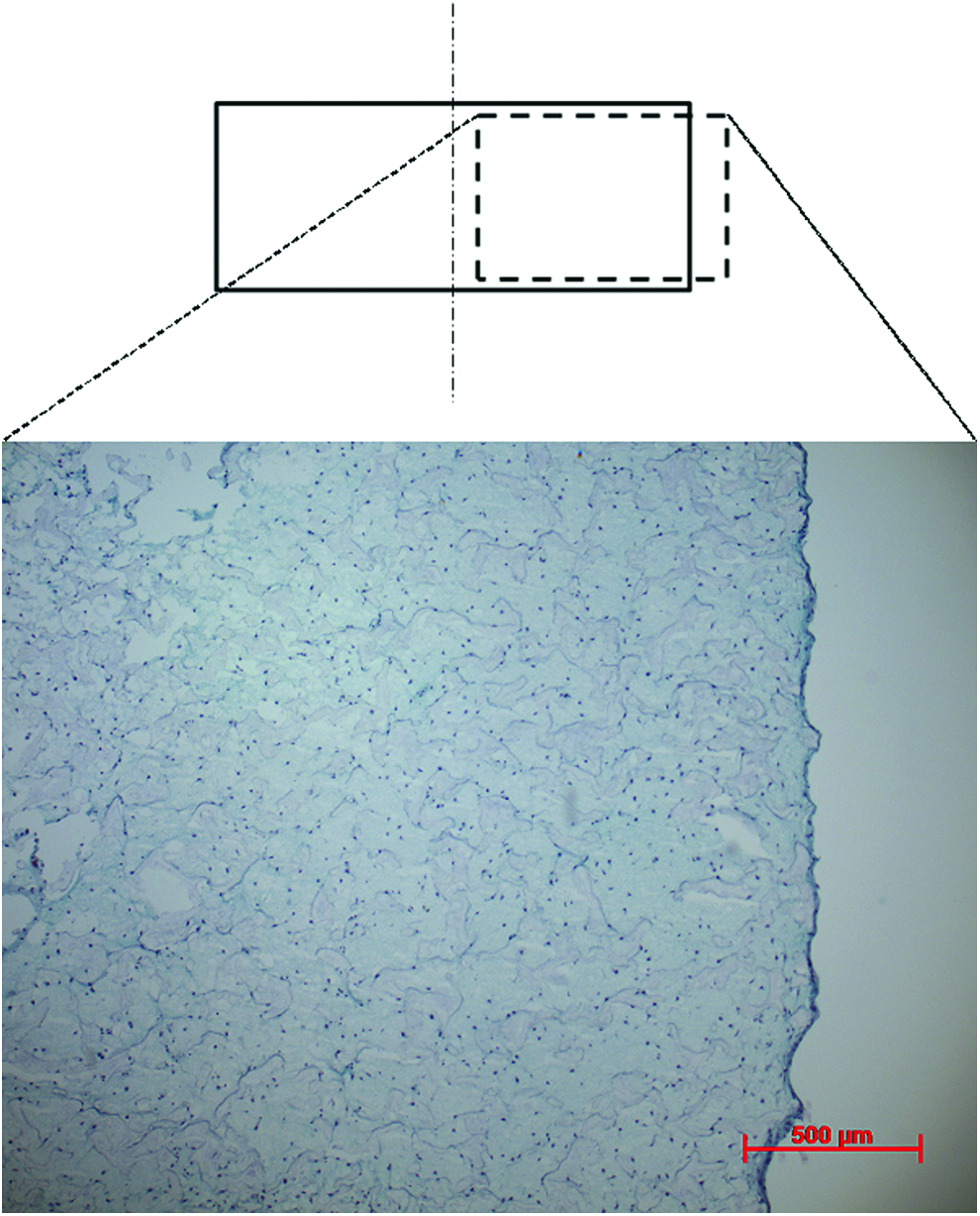
Characteristic toluidine blue-stained histological samples of the fibrin–polyurethane constructs 1 day after seeding, demonstrating an even distribution of cells within the construct. Color images available online at www.liebertpub.com/tea
Samples were assigned in quadruplicates to four groups where one group was cultured without any mechanical stimulation and three other groups were cultured using three different mechanical loading regimens using the bioreactor system. Briefly, a ceramic ball (32 mm in diameter) was pressed onto the scaffold, and compressive strain was applied along the cylindrical axis of the scaffold and interfacial shear load was generated by oscillation of the ball about an axis perpendicular to the scaffold's axis. Three different loading regimens of (i) dynamic compression alone, which comprised cyclic translational movement of the ceramic ball oscillating between 0.4 and 0.8 mm indentation at a frequency of 1 Hz, (ii) dynamic interfacial shear alone, which comprised a fixed indentation of 0.4 mm of the ceramic ball onto the scaffold and±25° oscillatory rotation of the ball at 1 Hz, and (iii) dynamic compression and interfacial shear combined, which comprised a cyclic translational movement of the ceramic ball oscillating between 0.4 and 0.8 mm indentation and±25° oscillatory rotation of the ball, both at a frequency of 1 Hz, were applied to the constructs. Mechanical stimulation was applied 1 h/day for 5 consecutive days per week over a period of 3 weeks.
Histology
For histological analysis, scaffolds were fixed in 70% methanol at 4°C and incubated in 5%
Statistics
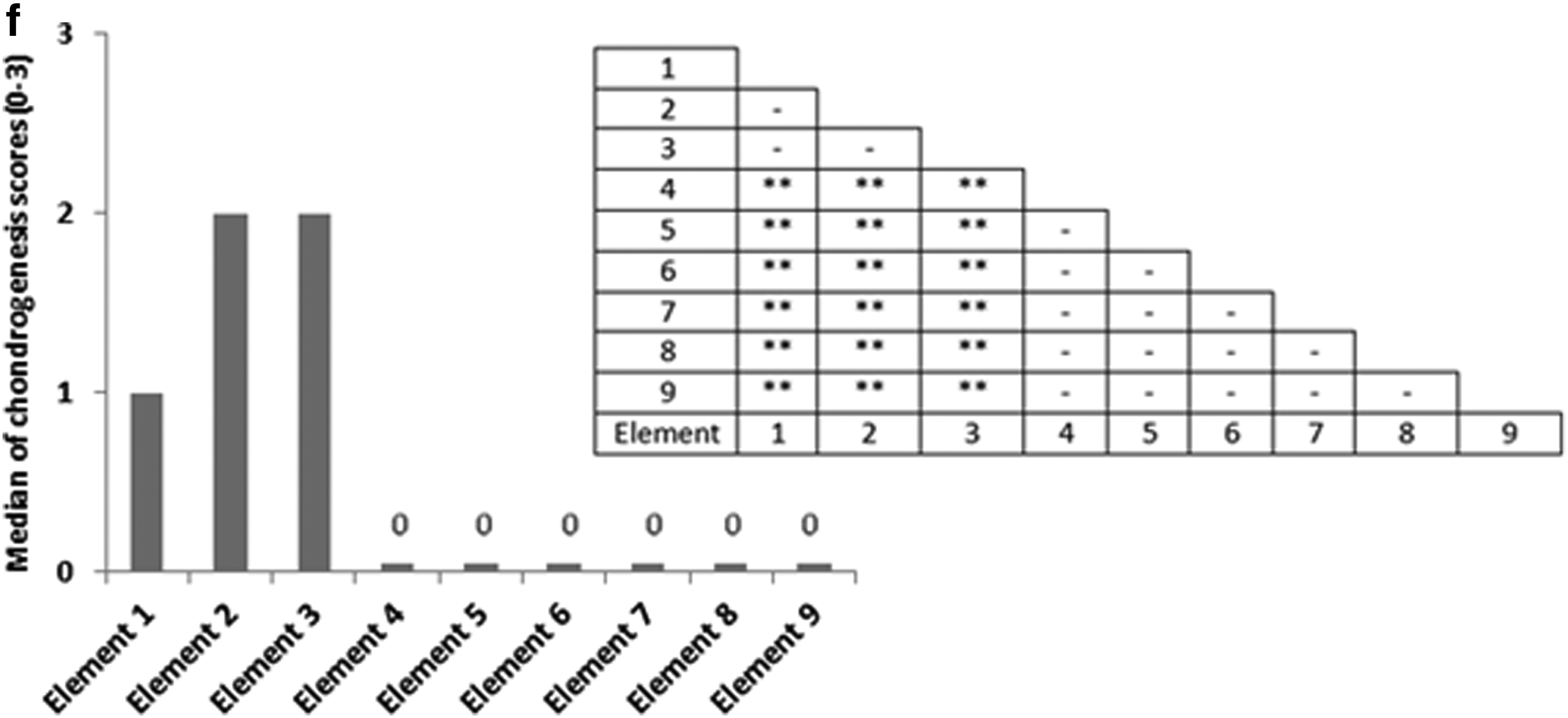
Nine key locations within the cross section of the histological samples were inspected qualitatively by blinded reviewers who identified the slides by number. The sections were scored ordinally between 0 and 3, that is, score 0 for no staining, score 1 for weak staining, score 2 for average staining, and score 3 for strong staining.
Statistical analysis was performed using the Mann–Whitney U test to compare the nine representative locations within each scaffold's cross section in terms of chondrogenesis based on the described ordinal scoring scheme.
Mechanical characterization experiments
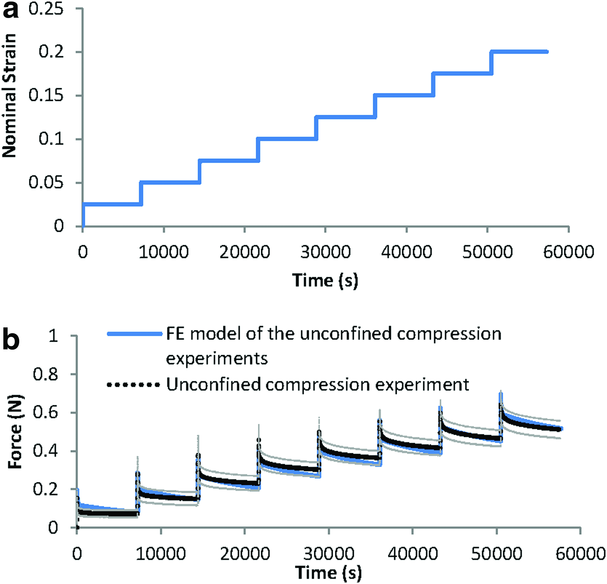
Cylindrical (8 mm diameter×4 mm thickness) polyurethane and fibrin–polyurethane composite scaffolds were prepared as described earlier for mechanical characterization experiments without cells. Unconfined compressive stress relaxation experiments were conducted on the specimens (n=6, i.e., six polyurethane scaffolds and six polyurethane–fibrin composite scaffolds) using a Bose-Electroforce™ testing machine (ELF 3220; Bose Corporation, Eden Prairie, MN) equipped with a 2.5-N load cell (type 8432-2.5; Burster, Gernsbach, Germany), whereas the samples were kept irrigated in a PBS bath. Contact between the samples and the upper plate was established by lowering the upper plate until the reaction force reached 0.02 N.
To capture the stress–relaxation response, successive compressive strain steps of 2.5% (nominal strain) were applied to the samples with each ramp applied at a strain rate of 0.25%/s. Each step was followed by a 2-h relaxation period while the displacement was maintained constant and the load cell recorded the axial force. Meanwhile, a digital precision camera (AxioCam HRc; Zeiss, Jena, Germany) recorded the lateral deformation of the samples to calculate the Poisson's ratio.
Permeability of the samples (n=6) was tested using a custom-built permeability test rig whereby a hydrostatic pressure gradient (1 m pressure head) was applied across the thickness of the scaffolds and the flow of medium through the sample was quantified. The permeability of the samples was then calculated using Darcy's law.
40
where V is referred to as the effective fluid velocity,
Constitutive modeling of the mechanical response of the scaffolds
The fibrin–polyurethane composite scaffold was modeled treating the scaffold as a homogenized poro-viscoelastic medium in a consolidation analysis using Abaqus 6.10 (Simulia, Providence, RI). As such, the scaffold as a biphasic mixture was assumed to be compressible given that the incompressible fluid phase could be exuded from the solid matrix. Due to the high permeability of the scaffolds compared to the native cartilage, that is, 6.92×10⁻¹⁰ m 4 /N·s for the composite scaffold versus (0.1–10)×10−15 m 4 /N·s for native cartilage, 42 the contribution of the fluid phase to the load bearing capacity and the observed relaxation response of the scaffolds is negligible given that the interstitial fluid can be easily exuded from the matrix. This was ensured by assigning a fully elastic response for the solid matrix in a poro-elastic FE model of the unconfined compression experiments, which elicited no stress relaxation, showing that the stress–relaxation response observed in the experiments is fully related to the viscous properties of the solid matrix. Subsequently, to develop a constitutive model for the scaffold, an inverse FE modeling approach was utilized whereby an FE model of the actual unconfined compression experiment was developed and a reversed model fitting was conducted using an iterative approach. To simulate the unconfined compression tests, the bottom surface of the scaffold was constrained in the axial direction and an axial displacement consistent with the compression experiments was applied to the upper surface. Fluid was allowed to flow freely from the lateral surface of the scaffolds by assigning a pore pressure of 0 to the lateral surface nodes and in contrast no fluid was allowed to flow from the top and bottom surfaces where the scaffold is in contact with the parallel plates. In Abaqus, this boundary condition is assumed as default and no pore pressure boundary conditions are required. The permeability of the scaffold was directly implemented from the permeability tests. The elastic response of the scaffold was linear in the tested range and isotropic given that the equilibrium elastic response, that is, stress-strain data points following relaxation of the loading steps showed a linear relationship and there was no preferred material orientation in the scaffold. Geometric nonlinear effects were taken into account, and large displacement formulation was used. A reversed FE model approach for parameter fitting was used whereby the material parameters related to the solid matrix were updated iteratively until FE predictions matched the outcome of the compression experiments (Tables 1 and 2).
The behavior of the solid phase and the fluid phase of the material were coupled using an effective stress concept whereby an additive decomposition of the stress caused by external loading,
where
where V is referred to as the effective fluid velocity, φ is the porosity of the material, Vfluid is the pore fluid velocity, K is the permeability of the material, and P is the pore pressure 41 (Table 1).
The stress–relaxation response was associated to the deviatoric deformations of the matrix44,45 and a linear isotropic viscoelastic model was applied to the deviatoric part of the aforementioned effective stress on the matrix as follows46–48
:
where τ(t) is the deviatoric part of the effective stress on the matrix, γ(s) is the time-dependent shear strain, and gR(t) is the dimensionless relaxation modulus defined as:
with GR(t) denoting the time-dependent shear modulus that characterizes the material's response.46,48 The viscoelastic response of the material is then defined by the following Prony series expansion of the dimensionless relaxation modulus:
where
FE model of the bioreactor assembly
Following the determination of the constitutive mechanical parameters, the parameters were employed in an FE model of the bioreactor system (Fig. 4). The FE model enabled to determine the mechanical stimuli that MSCs were exposed to in different locations within the fibrin–polyurethane composite scaffolds.
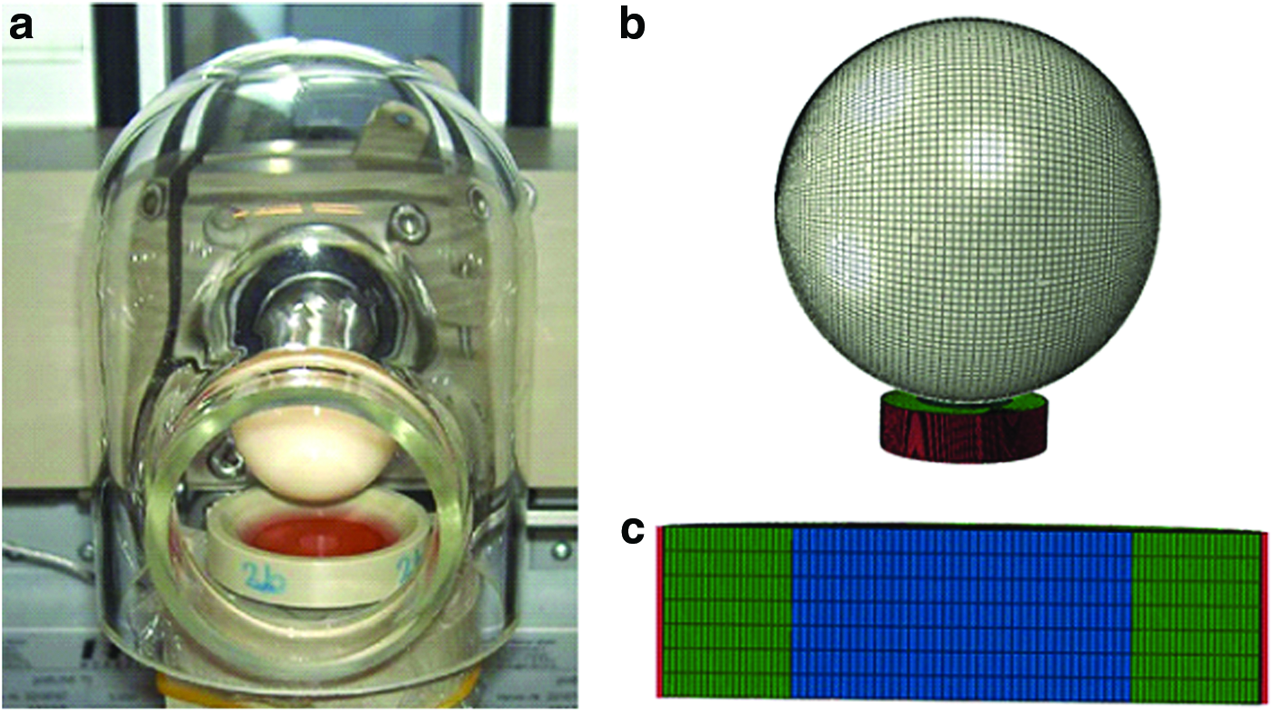
The PEEK holder was modeled as a cup-shaped discrete rigid impermeable body with a diameter of 14 mm and 4 mm depth and was meshed with 44′675 linear quadrilateral Abaqus elements of type R3D4. The polyurethane ring has an internal diameter of 8 mm, external diameter of 14 mm, and a depth of 4 mm, which was meshed with 42′000 linear hexahedral elements of type C3D8RP. The fibrin–polyurethane composite scaffold has a diameter of 8 mm and a depth of 4 mm, which was meshed with 9′604 linear hexahedral elements of type C3D8RP. The ceramic hip ball was modeled with 12′800 elements in total, of which 12′480 were linear quadrilateral elements of type R3D4 and 320 were linear triangular elements of type R3D3, although only the quadrilateral elements were involved in contact (Fig. 4). The mesh densities and dimensions were chosen based on mesh sensitivity analyses and to prevent element distortions given the very soft material properties of the constructs.
Contact pairs were defined using surface–surface discretization and finite sliding between all contacting surfaces. The rigid bodies were all assigned as the master surface in the relevant contact pairs, and the outer surface of the composite scaffold was assigned as the master surface in the fibrin–polyurethane composite scaffold and polyurethane ring contact pair. The tangential behavior of the contact pairs were defined using the penalty friction formulation with automatic overclosure tolerances in contact controls while all other options were set to default. 49 The friction coefficient between the ceramic ball and the fibrin-polyurethane scaffold was set to 0.1 as estimated based on measurements on the frictional behaviour of the fibrin-polyurethane constructs. The bottom surface of the fibrin–polyurethane composite scaffold was constrained in the radial and circumferential directions, representing a sticking boundary condition given its adhesion to the PEEK holder due to fibrin. Abaqus ensures the continuity of the pore pressure field across two contacting bodies and as such fluid flow occurred between the lateral surface of the composite scaffold and the inner surface of the polyurethane ring. Where an impermeable rigid body (ceramic hip ball/PEEK holder) was in contact with a porous permeable body, no fluid flow occurred in the direction normal to the contacting surfaces. Upon detachment of the surfaces, interstitial fluid flow was allowed at the permeable surface. A zero pore pressure was assigned to the top surface of the polyurethane ring to allow free fluid flow through its top surface. The ceramic ball has two degrees of freedom where it can rotate around its axis, which is parallel to the top surface of the scaffold to apply sliding shear and also its axis of rotation could translate vertically to apply cyclic compression. These two movement patterns could be set to act alone or simultaneously together. In the FE model, a rigid body movement, which is based on the employed in vitro loading protocols, was applied to the ceramic ball, and the PEEK holder was fully constrained. The ceramic ball was compressed 0.4 mm into the scaffold in a 10-s long initial loading step, and five preconditioning cyclic loading steps were applied by oscillating the ceramic ball between 0.4 and 0.8 mm penetration. As such the values of mechanical stimuli, that is, strain fields and pore fluid velocity and pressure field, were based on the sixth loading cycle. The simulations required up to 120 h to complete on a workstation equipped with a quad-core Xeon 2.67 MHz processor and 12 GB RAM depending on the loading regimen applied.
Results
The stress-strain field and also the pore fluid velocity and pressure fields within the fibrin–polyurethane composite scaffolds were quantified by the FE model of the bioreactor assembly under the three loading regimens of (i) dynamic compression alone (ii) dynamic interfacial shear alone, and (iii) dynamic compression and interfacial shear combined. Comparing the strain fields among the three loading regimens revealed the most significant differences in the peak magnitude of the maximum principal strain fields. The peak magnitude of the maximum principal strain in the cyclic compression alone, that is, loading regimen (i) was compressive and reached a value of 6.7% mainly on the top surface of the scaffold. In the loading regimen (ii) where only interfacial shear loading was applied, this value was quantified to be again compressive with a value of 9.8% with the peak values localized at the top lateral edges of the scaffolds in the direction of the ceramic ball cyclic rotation. Compression and interfacial shear loading combined, that is, loading regimen (iii), however, revealed the highest magnitude of the maximum principal strains compared to the other regimes with a peak magnitude of 13% in the compressive mode, which was localized at the top edges of the scaffold in the direction of the ceramic ball rotation. As such, the highest magnitude of the maximum principal strains was obtained when combined compression and interfacial shear (regimen iii) were applied with a value 1.94- and 1.32-fold higher than compression alone (regimen i) and interfacial shear alone (regimen ii), respectively (Fig. 5).
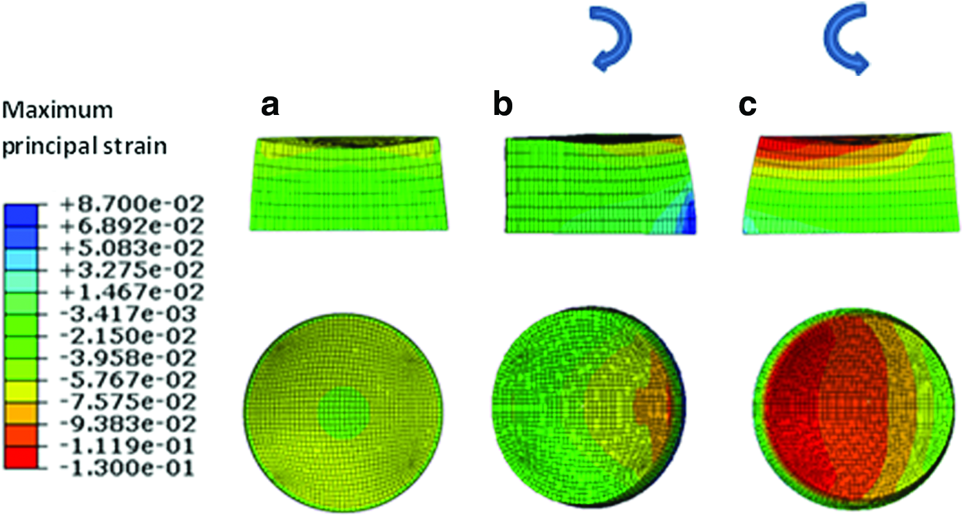
Maximum principal strain field.
As shown in Figure 5, in all three loading regimens, the highest magnitudes of the maximum principal strains localized at the top surface of the scaffolds and were of compressive mode as indicated by their negative sign in Abaqus.
When the pore fluid velocity fields where compared among the three different regimes, the peak values of the pore fluid velocity were found to be 1.46, 1.1, and 1.8 mm/s for compression alone (regimen i), interfacial shear alone (regimen ii), and compression and interfacial shear combined (regimen iii), respectively (Fig. 6). Nevertheless, the peak values of the pore fluid velocity are notably higher than the values reported for articular cartilage under physiological loads due to significantly higher permeability of the fibrin–polyurethane composite scaffolds compared to that of cartilage, that is, 6.92×10⁻¹⁰ m 4 /N·s for the composite scaffold versus (0.1–10)×10−15 m 4 /N·s for native cartilage. 42 The values of the pore fluid pressure, however, were also extremely low compared to articular cartilage with a maximum value of 366 Pa for the compression alone (regimen i), a maximum value of 64 Pa for the interfacial shear alone (regimen ii), and 420 Pa for compression and interfacial shear combined (regimen iii). In articular cartilage, interstitial fluid pressure can reach values higher than 12 MPa under physiological loads.50–52
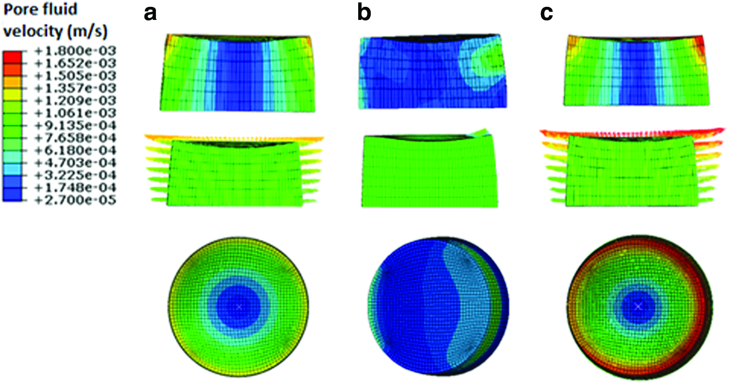
Maximum pore fluid velocity field.
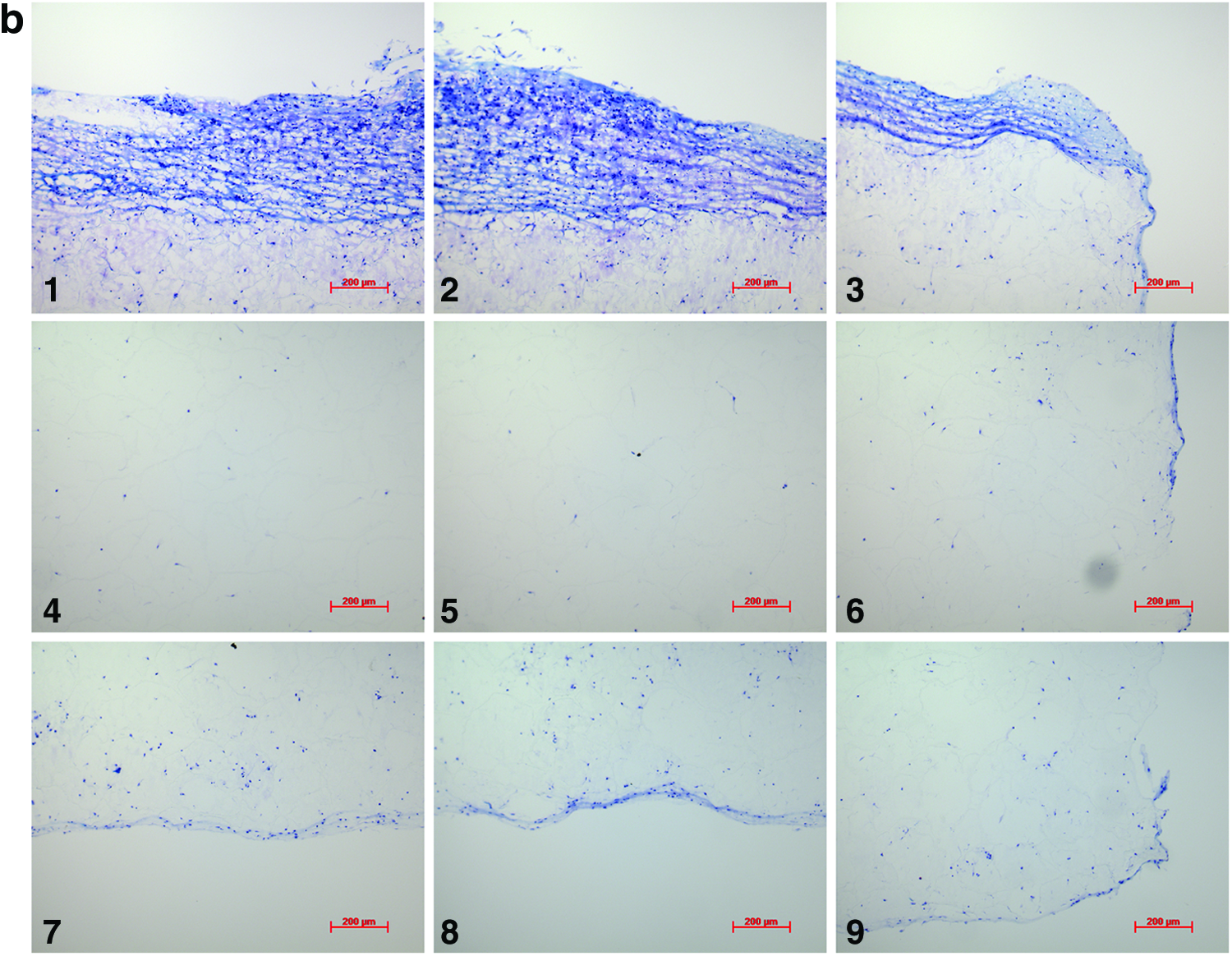
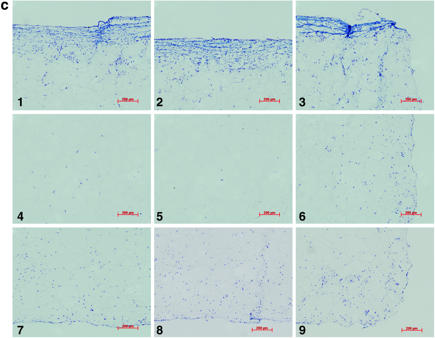
Analysis of the histological samples stained with toluidine blue revealed that only samples exposed to compression and interfacial shear combined (regimen iii) stained positive for proteoglycan-rich ECM based on the level of metachromatic staining (Fig. 7). Further examination of the histological samples of the constructs, which were exposed to compression and interfacial shear combined (regimen iii) and scoring the key locations of the scaffolds for chondrogenesis, revealed that chondrogenesis mainly occurred at the top areas of the scaffolds and increased toward the scaffold edges (Fig. 7). Under free-swelling conditions, a fibrous capsule can be seen around the scaffold, which is most prominent on the upper surface. The lower surface, and to a greater extent, the central areas of the scaffold demonstrate a loss of viable cells. Compression alone increased cellularity throughout the scaffold compared to free swelling, and the fibrous capsule around the scaffold was reduced. However, no purple metachromatic staining could be detected indicating the absence of a proteoglycan-rich ECM. Also, under interfacial shear alone, no purple metachromatic staining could be seen and the fibrous capsule around the scaffolds was reduced compared to free swelling. In stark contrast, after the application of combined compression and shear, the cellularity of the scaffold clearly increased and key areas 1–3 located at the upper side of the construct cross section demonstrated metachromatic toluidine blue staining (purple stain) indicating the presence of proteoglycan-rich ECM within the scaffolds.
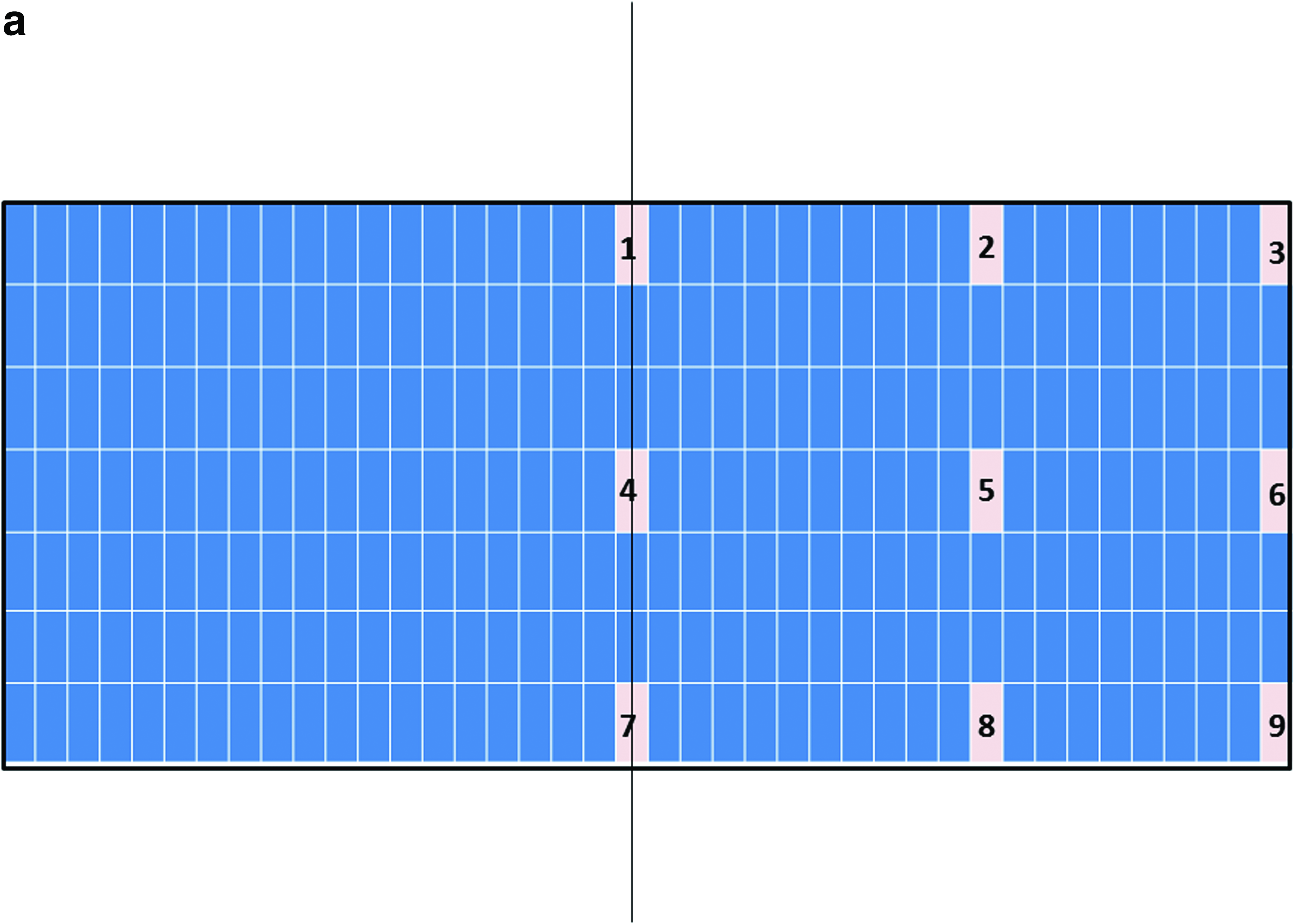
Nine key locations within the constructs were analyzed for chondrogenesis and scored from 0 to 3 for proteoglycan-rich extracellular matrix (ECM) based on their level of metachromatic staining (purple stain), score 0 for no staining, score 1 for weak staining, score 2 for average staining, and score 3 for strong staining. Representative toluidine blue-stained histological images of each of the key areas (1–9) of the constructs are provided for each loading condition following 3 weeks of culture.


Discussion
As shown here based on the histological assessment of the proteoglycan-rich ECM, compression alone (regimen i) and interfacial shear alone (regimen ii) did not lead to the deposition of sulphate-rich glycosaminoglycan (GAG) within the fibrin–polyurethane composite scaffolds. In stark contrast, the combination of the compression and interfacial shear (regimen iii) induced significant chondrogenesis at the top surface of the scaffolds.
Interestingly, the FE model of the bioreactor assembly revealed that the maximum principal strain and pore fluid velocity fields were significantly different in the constructs exposed to compression and interfacial shear combined (regimen iii) compared to the other two groups. This was further corroborated by comparing other measures of strain, specifically octahedral shear strain, which has been previously suggested as a mechanical contributor to tissue differentiation in vivo, such as during bone fracture healing or implant interfacial healing.53,54 Nevertheless, no meaningful difference could be determined in terms of octahedral shear strains when exposure to compression and interfacial shear combined (regimen iii) was compared to compression alone (regimen i) (Supplementary Fig. S1; Supplementary Data are available online at www.liebertpub.com/tea). Therefore, the principal strains and the pore fluid velocity were deemed as potential candidates for the regulation of chondrogenesis within the constructs and their role was further scrutinized.
Given that the distribution of chondrogenesis throughout the samples exposed to compression and interfacial shear combined (regimen iii) was highly heterogeneous, we hypothesized that this heterogeneity is to a great extent due to the heterogeneity of the mechanical stimuli. As such, the distribution of the maximum principal strains and the pore fluid velocity field throughout the cross section of the constructs was examined and associated with the spatial distribution of chondrogenesis. In Figure 8, the values of the maximum principal strain and the pore fluid velocity are plotted against time for the nine key locations in the scaffolds during the loading cycle of the bioreactor in the loading regimen (iii). Association of the mechanical stimuli at these nine key locations to the chondrogenesis levels, based on the outlined scoring scheme shown in Figure 7, provided deciphering cues on mechanoregulation of chondrogenesis in the constructs.
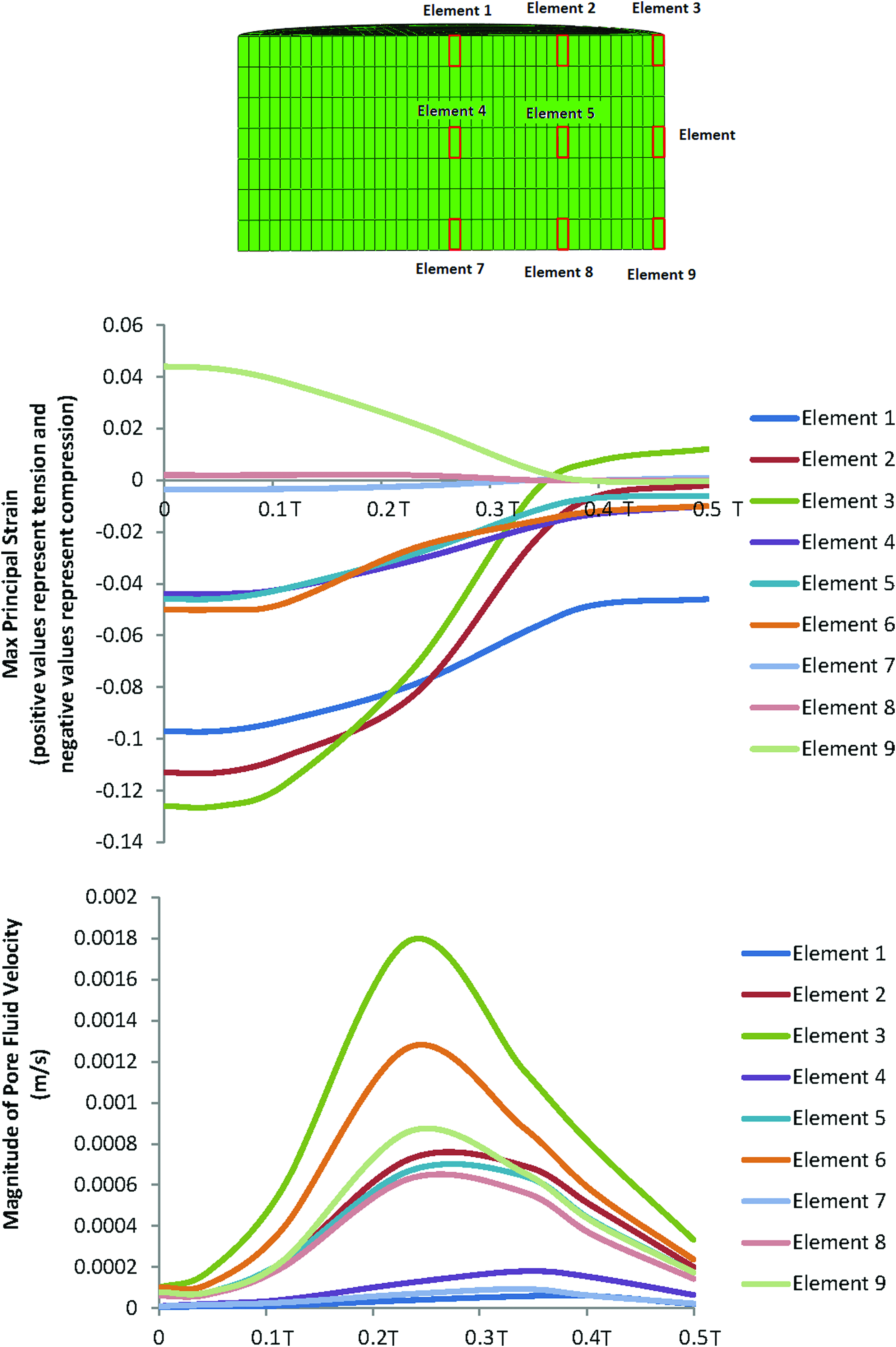
Changes of the maximum principal strain and the pore fluid velocity at nine locations within the scaffold's cross section during the loading cycle in the dynamic compression and shear combined group (regimen iii). (T is the period of the loading cycle.) Color images available online at www.liebertpub.com/tea
Significant chondrogenesis only occurred at the top surface of the scaffolds in key locations/elements 1, 2, and 3 with highest median in elements 2 and 3. Examining the principal strain field at these three locations reveals that (i) the three principal strains (i.e., minimum, mid, and maximum) are compressive and (ii) the magnitudes of the minimum compressive principal strains* is highest in these elements having magnitudes equal or greater than 10%. Also, there is a trend toward higher chondrogenesis with the increase in the minimum compressive principal strains from element 1 with a value of ∼10% toward element 2 and element 3 with a value of 13% (Fig. 8). On the other hand, the maximum pore fluid velocity also occurs in element 3; however, the second and third highest pore fluid velocities are in elements 6 and 9 (the lateral surface of the scaffolds) where no significant chondrogenesis occurred. In addition, element 2 with the highest chondrogenesis score also experiences the second highest minimum compressive principal strains, while the pore fluid velocity is as low as 38% of the pore fluid velocity in element 3, and also in element 1, significant chondrogenesis occurs, although the pore fluid velocity is lowest.
As such, the trends clearly show that chondrogenesis levels correlate best with the level of the minimum compressive principal strains and this response is threshold dependent with a threshold value of 10%. This hypothesis on the threshold-dependent response of MSCs to compressive principal strains can be further corroborated by examining the principal strain field in the interfacial shear alone (regimen ii) group for which although the presented chondrogenesis scores show no significant proteoglycan-rich ECM based on toluidine blue staining (absence of metachromatic staining), Schätti et al. reports a trend toward chondrogenesis based on GAG accumulation and also gene expression analysis. 35 In this group, the principal strains at element 3 are all compressive and have a minimum magnitude of nearly 10% (Fig. 5; Supplementary Fig. S2).
Another strong indication for the key regulatory role of the compressive principal strains in our study compared to the role of pore fluid velocity can be appreciated when comparing regimen (i) with regimen (iii) (Figs. 8 and 9). In compression alone (regimen i), the pore fluid velocity field reached a value of 1.4 mm/s at the location of element 3, yet neither a significant chondrogenesis nor a trend toward chondrogenesis was observed in these constructs. In contrast, in regimen (iii), the level of pore fluid velocity at element 2 was 57% lower but significant chondrogenesis occurred in this element. The value of the minimum compressive principal strain at element 3 in compression alone (regimen i) is 45% lower than the threshold value of 10% for the compressive principal strains. Taken together, these results suggest that the magnitude of the fluid velocity as the trigger of chondrogenesis can be ruled out in our in vitro setup. Consistently, fluid velocity even at physiological levels in perfusion bioreactor studies used for cartilage tissue engineering has been generally shown not to be beneficial for chondrogenesis 15 and therefore in cartilage tissue engineering applications fluid velocity is most likely only beneficial for the transport of oxygen, nutrients and metabolic waste products.

Changes of the maximum principal strain and the pore fluid velocity at nine locations within the scaffolds cross section during the loading cycle in the dynamic compression alone group (regimen i). (T is the period of the loading cycle.) Color images available online at www.liebertpub.com/tea
These insightful comparisons indicate that in the MSC-enriched fibrin–polyurethane composite scaffolds employed in this study, chondrogenesis occurred in locations where the principal strains were all compressive and the value of the minimum compressive principal strain was higher than 10%. In Figure 10, the configuration of the principal strains at the top lateral elements of the constructs is schematically illustrated for the three loading groups. One can notice that in compression alone, where no chondrogenesis occurred, although the maximum compressive principal strain magnitude exceeds 20%, the magnitude of minimum compressive principal strain is significantly below 10% (Fig. 10). In the interfacial shear alone group (regimen ii), however, no metachromatic staining occurred, yet Schätti et al. showed a trend toward more chondrogenesis based on GAG accumulation and gene expression. 35 In this group, all three principal strains are compressive with a magnitude of ∼10% (Fig. 10). Finally, in the constructs exposed to compression and interfacial shear combined (regimen iii), in which significant metachromatic staining occurred, the three principal strains at the top surface of the constructs were all compressive with a magnitude higher than 10%.
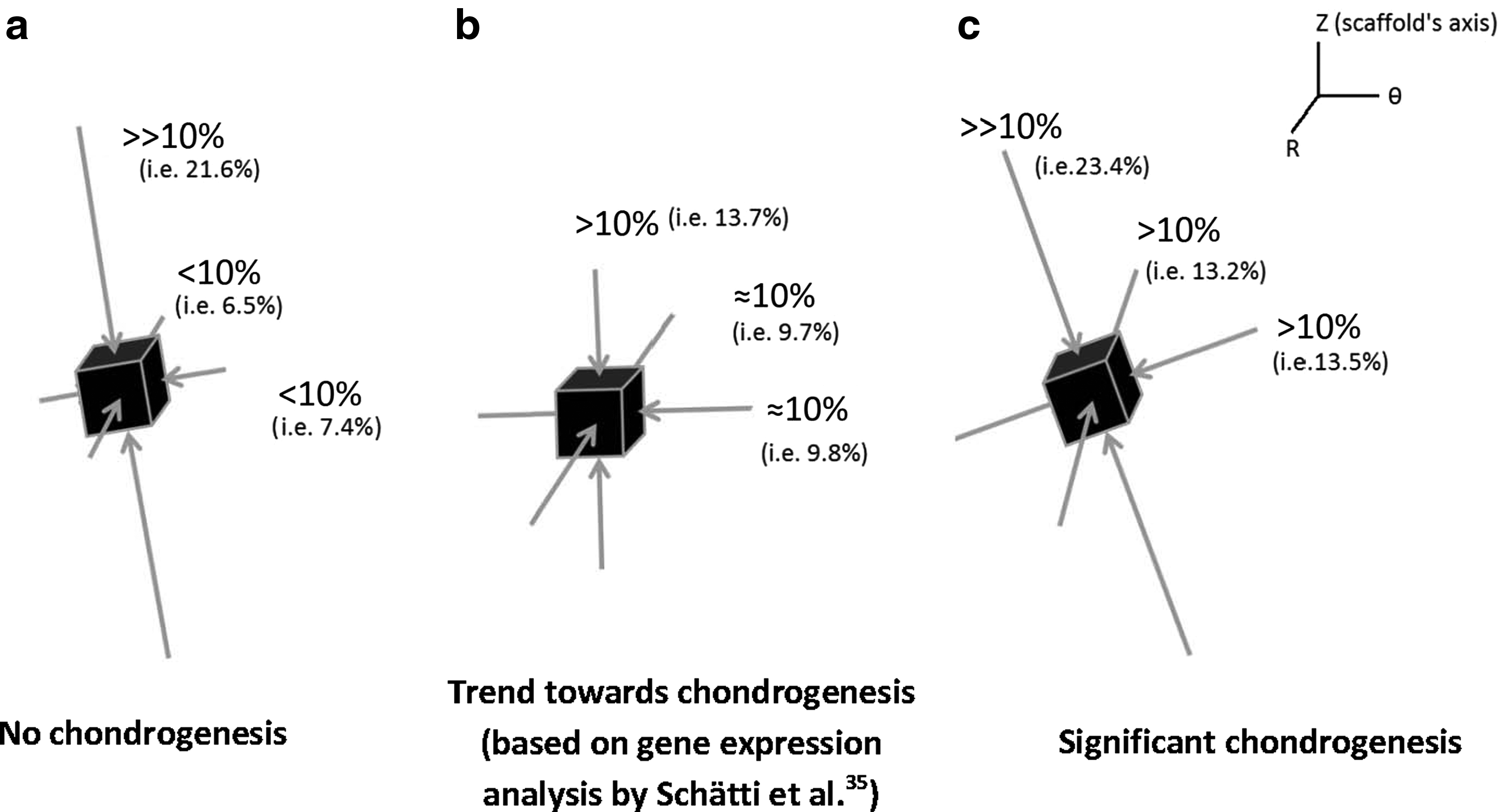
Schematic of the configuration of the principal strains at locations with the highest magnitudes of the minimum compressive principal strains (all principal strains are compressive)
To put the aforementioned findings on the regulatory role of the compressive principal strains into perspective, it is worth referring to the many in vitro studies, which have shown that the application of hydrostatic pressure (i.e., fluid pressure) to MSCs induces chondrogenesis.25,26,55,56 Indeed, in cartilage under physiological loading, hydrostatic pressure (i.e., fluid pressure) is a dominant mechanical stimulus, which promotes the maintenance of chondrogenic phenotype. Such findings, together with the results of this study, render it intuitive to hypothesize that a mechanical loading regimen, which induces triaxial compression of the matrix also favours chondrogenesis analogic to the influence of fluid phase pressurization and this response is threshold dependent. This hypothesis can be clearly corroborated by the configuration of the principal strains at the locations where chondrogenesis occurred. Furthermore, the influence of the hydrostatic pressure (i.e., fluid pressure) on the chondrogenic induction in the fibrin–polyurethane composite scaffolds can be ruled out given that due to the high permeability of the scaffolds, the pore pressure does not exceed a few hundred Pascals. In contrast, the level of hydrostatic pressure (i.e., fluid pressure), which has been suggested to induce chondrogenesis in vitro is in the range of 1–10 MPa.25,26,55,56 Thus, this study shows that under complex multiaxial loading in fibrin–polyurethane composite scaffolds chondrogenesis can be alternatively induced by triaxial dynamic compressive deformations of the matrix with a threshold of 10% for the minimum compressive principal strain. In the uniaxial compression regimen applied to the fibrin–polyurethane composite scaffolds, this level of the minimum compressive principal strains is not induced in the matrix and due to the high permeability of the constructs the hydrostatic pressure remains negligible and therefore no chondrogenesis occurs.
This argument further highlights the importance of the mechanical properties of the scaffolds in terms of the cellular response to external loading of tissue-engineered constructs for cartilage regeneration. The type and level of mechanical stimuli experienced by cells may be completely different within different scaffolds even with application of the same external mechanical loading regimen. For instance, in the fibrin–polyurethane composite scaffolds used in the present study, hydrostatic pressure buildup due to the application of external loading was negligible because of the high permeability of the scaffolds. On the contrary, agarose gels can be fabricated to have a permeability more comparable to that of articular cartilage, 57 in which case, buildup of hydrostatic pressure (i.e., fluid pressure) due to the application of even lower uniaxial compression regimens might be sufficient to induce chondrogenesis. This could explain why in contrast to the fibrin–polyurethane constructs, in agarose gels uniaxial compression in the absence of TGF-β is sufficient to induce chondrogenesis. 20 Interestingly, chondrogenesis in agarose gels has been shown to be highest where maximum hydrostatic pressures (i.e., fluid pressure) occur rather than where maximum uniaxial compressive strains occur, 20 which corroborates the hypothesis that to induce chondrogenesis, MSCs should be compressed by means of hydrostatic pressure or alternatively by three-dimensional (triaxial) compressive deformations of the matrix, which in the case of fibrin–polyurethane composite scaffolds must exceed a threshold value of 10% (i.e., minimum compressive principal strain of 10%).
In addition to the permeability of the scaffolds, the stiffness of the constructs can alter the mode of deformations that cells experience. In fibrin–polyurethane composite scaffolds, due to the very low Young's modules of the scaffolds compared to mature cartilage, that is, 41 kPa compared to 300–800 kPa for articular cartilage, 58 the scaffolds were compressed laterally due to the friction between the scaffold and the ceramic ball when interfacial shear movement was applied. This mode of deformation could be potentially different depending on the mechanical properties of the constructs. Therefore, quantitative assessment of the mechanical stimuli using methods such as FE is essential to decipher the mechanoregulation of cellular behaviour in different scaffolds.
While the main outcome measurement from this study was GAG content, in the recent study by Schätti et al., 35 a more elaborate assessment of the biological outcome, which is presented here, has been presented using gene expression studies and exhaustive biochemical and immunohistochemical analyses. It has been shown that immunohistological staining for aggrecan matched the GAG staining as expected. Under the loading conditions applied, small differences in collagen were seen between the groups, also at the mRNA level. The only group to stain positively for collagen type II immunohistochemistry, however, was the combined compression and shear group where collagen type II was only found in the top key elements of the scaffold. Of note, as is common with human chondrogenic studies, the same study demonstrated that the collagen type II staining was weak in comparison to GAG and thus was not included in the present study (Schätti et al., 35 and data not shown). Whether a different mechanical stimulus is required for collagen type II synthesis or synthesis and deposition of collagen type II is slower is yet to be determined. Within regimen ii, changes were also seen at the mRNA, but not protein, level. Changes in mRNA need to be interpreted with caution as many of the genes investigated are expressed at very low levels in undifferentiated cells. Thus, a 100-fold increase may seem large but is perhaps of little biological significance. It is also often seen that a large increase at the mRNA level does not translate to a large increase in protein synthesis. 59 Ultimately, it is the production of a functional cartilage matrix, which is the desired outcome.
Finally, it is worth mentioning the limitation of the present study concerning the influence of mass transport within the constructs. Oxygen concentration and also the concentration of nutrients and cellular waste products are not accounted for in the simulations conducted in this study. Low oxygen concentration in the centre of the scaffolds might have potentially contributed to the absence of chondrogenesis. Nonetheless, hypoxia has been shown to support chondrogenesis in vitro 60 and hence it remains to be further investigated as to whether low oxygen concentration in the centre of the constructs is a friend or foe. Although occurrence of significant chondrogenesis on the top surface of the scaffolds might be inferred as a mass transport effect in the first glance, the fact that chondrogenesis only occurs on the top surface of the constructs exposed to regimen (iii) and not in the other two loading groups clearly shows that the chondrogenesis at the top of the constructs is related to the mechanical stimulation and is not a mass transport effect. As can be seen in Figure 7, in the control scaffolds, which are not mechanically stimulated, cells are no longer seen in the middle of the constructs (key locations 4–6) and the cellularity is reduced at the lower edges (key locations 7–9). This is partially recovered in the constructs under compression alone, potentially due to the improved fluid flow, which improves mass transport within the constructs. The cellularity is greatly improved with combined compression and shear, however, still no chondrogenesis occurs other than in the key locations 1–3. As we know, combined compression and shear induces TGF-β production, 35 which may account for the increased survival in the combined compression and shear group. Nevertheless, this remains merely as a speculation and requires further investigation. On the other hand, the simulations presented in this study are based on the mechanical properties of the scaffolds measured at day 0 and as such the influence of dynamic events, which occur within the constructs such as the influence of neotissue formation on the mechanical properties during culture specifically, are not accounted for. Measuring such changes could be a next step in unravelling the relation between the mechanical environment and the regulation of chondrogenesis in tissue-engineered constructs.
Conclusions
In this study, a dual computational and in vitro approach was employed to decipher the mechanoregulation of chondrogenesis in fibrin–polyurethane composite scaffolds enriched with hMSCs for cartilage regeneration. The study identified compressive principal strains as the key regulator of chondrogenesis in the fibrin–polyurethane constructs. Although, dynamic uniaxial compression did not induce chondrogenesis, multiaxial loading of the constructs by the application of dynamic compression and interfacial shear loads could induce significant chondrogenesis at locations where all principal strains were compressive and had a minimum magnitude of 10%. Thus, based on the computational and in vitro results of this study, it can be inferred that dynamic triaxial compressive deformations of the matrix are sufficient to induce chondrogenesis in a threshold-dependant manner, even where hydrostatic pressure is negligible. In fibrin–polyurethane composite scaffolds due to the high permeability of the constructs, high enough hydrostatic pressures could not be induced by dynamic uniaxial compression and instead chondrogenesis is induced by three-dimensional compressive deformations of the matrix using a complex dynamic multiaxial loading regimen.
Footnotes
Acknowledgments
This study was funded by the Research Foundation-Flanders (FWO) postdoctoral fellowship awarded to H.Z. and FWO grant G.0858.12 and is a contribution to the NAMABIO project, which is funded as an EU COST Action (MP1005).
Disclosure Statement
No competing financial interests exist.
*
Abaqus, compressive principal strains are signed negative by convention, hence maximum principal strains with negative sign can be referred to as the minimum compressive principal strains (i.e., the ones that are least negative) emphasizing that the other two principal strains at that location are also compressive and have a larger magnitude (i.e., more negative).
References
Supplementary Material
Please find the following supplemental material available below.
For Open Access articles published under a Creative Commons License, all supplemental material carries the same license as the article it is associated with.
For non-Open Access articles published, all supplemental material carries a non-exclusive license, and permission requests for re-use of supplemental material or any part of supplemental material shall be sent directly to the copyright owner as specified in the copyright notice associated with the article.