
Abstract
There has been much research over the past two decades with the aim of engineering cartilage constructs for repairing or restoring damaged cartilage. To engineer healthy neocartilage, the constructs must have mechanical properties matching those of native cartilage as well as appropriate for the loading conditions of the joint. This article discusses the mechanical behavior of native cartilage and surveys different types of tensile, compressive, and shear tests with their limitations. It also comprehensively reviews recent work and achievements in developing the mathematical models representing the mechanical properties of both native and engineered cartilage. Different methods for enhancing the mechanical properties of engineered cartilage are also discussed, including scaffold design, mechanical stimulation, and chemical stimulation. This article concludes with recommendations for future research aimed at achieving engineered cartilage with mechanical properties matching those found in native cartilage.
Introduction
Tissue engineering aims to replace damaged tissues with artificial tissues grown in the controlled laboratory environment. For this, three-dimensional (3D) constructs, or scaffolds, are created from biocompatible and biodegradable materials and then seeded with cells such as chondrocytes. The scaffold provides cells with a 3D structure and mechanical support for their attachment and proliferation, ultimately growing into a functional tissue-engineered construct (TEC). The TEC is then implanted into a patient and, with time, hopefully integrates itself with the surrounding natural cartilage. Eventually, the cells will secrete their own extracellular matrix (ECM) that is able to withstand the mechanical forces seen in the joints, while the scaffold biodegrades. In this healing process, a crucial role is played by the mechanical properties of the TEC, which, ideally, must match those of native cartilage. Considerable progress has been made in the past two decades to fulfill the requirement of mechanical properties imposed on the TEC as applied to the repair of damaged cartilage. This article aims to review this progress with emphasis on the different mechanical testing procedures, mathematical representations or models of the mechanical properties of cartilage and TECs, and methods to enhance the mechanical properties of TECs. The challenges in these aspects are also discussed, along with the recommendations for future research aimed at achieving the desired mechanical properties of TECs for cartilage tissue engineering applications.
Cartilage Structure and Response to Mechanical Forces
Organization and composition of adult articular cartilage
Articular cartilage is an organized tissue composed mainly of water, collagens, proteoglycans (PG), and chondrocytes. These components interact with one another to give cartilage the strength to withstand the mechanical forces or loads it experiences. Water, the most prevalent component, accounts for 70%–85% of the total weight of articular cartilage; next is collagen, which makes up between 60% and 70% of the cartilage's dry weight. 4 Collagen type II makes up most of the collagen matrix, in addition to types I, III, V, VI, IX, XI, XII, and XIV to lesser degrees. 5 The third most prevalent component of articular cartilage, comprising ∼30% of the dry weight is PG, which is made up of a number of sulfated glycosaminoglycans (GAGs) on a hyaluronic acid (HA) backbone. 6 The water, collagen, and PG together are referred to as the ECM of the tissue. Chondrocytes are responsible for producing and assembling the ECM components but only make up 2% of the volume of adult articular cartilage. 7
There is a large amount of zonal variation in the composition and orientation of the ECM components of articular cartilage. Adult articular cartilage can be divided into four separate zones, that is, the superficial zone, middle zone, deep zone, and calcified cartilage (Fig. 1). 8 The chondrocyte concentration is at its highest within the superficial zone, 9 where the collagen fibrils run parallel to one another and the articular surface. 8 This collagen fibril arrangement gives the superficial zone the highest strength among the four zones, 10 allowing the cartilage to withstand the mechanical forces (e.g., shear, compressive stress, and tensile stress) experienced at the surface.

Zonal organization of hyaline cartilage, showing the superficial, middle, deep, and calcified cartilage zones.
The middle zone is rich in PG and contains larger collagen fibrils in a more random arrangement. 9 In the deep zone, the chondrocyte concentration is low and the PG concentration and collagen fibril diameter are at a maximum.8,9 The high collagen and PG concentration makes the deep zone the most resistant to compressive forces. 11 Next to the subchondral bone, the cartilage becomes mineralized, forming calcified cartilage, which has mechanical properties between the cartilage zones above and the bone below and which provides a good transition between the two. 8
Cartilage responses to mechanical forces
Two distinct mechanisms respond to the forces applied to cartilage: the resistance to interstitial fluid (water) flow through the ECM, and deformations of the ECM. 12 As mechanical forces are applied to the cartilage, a pressure gradient is generated in the interstitial fluid, causing fluid flow through the pores within the ECM. Because the pore size is small, fluid flow through them, referred to as the hydraulic permeability, is limited and therefore, causes significant flow resistance. 13 Moreover, the interaction between the negatively charged GAGs and the polar water molecules further limits fluid flow through the ECM pores. 6 This interaction combined with the hydraulic pressure gradient withstands as much as 95% of the mechanical force applied to the cartilage; the remaining 5% is achieved by ECM deformation. 12 This early fluid pressurization reduces the coefficient of friction between the articulating surfaces. 14 In healthy cartilage, the hydraulic permeability of the superficial zone is low and the pressures in the interstitial water in the deep and middle zones are relatively high. 15 These high internal pressures protect the ECM from most of the biomechanical loading. If these forces are transmitted through the solid ECM, it may lead to cartilage degeneration 16 ; thus, the variability of hydraulic permeability between patients may explain why some are more prone to joint diseases than others. 17
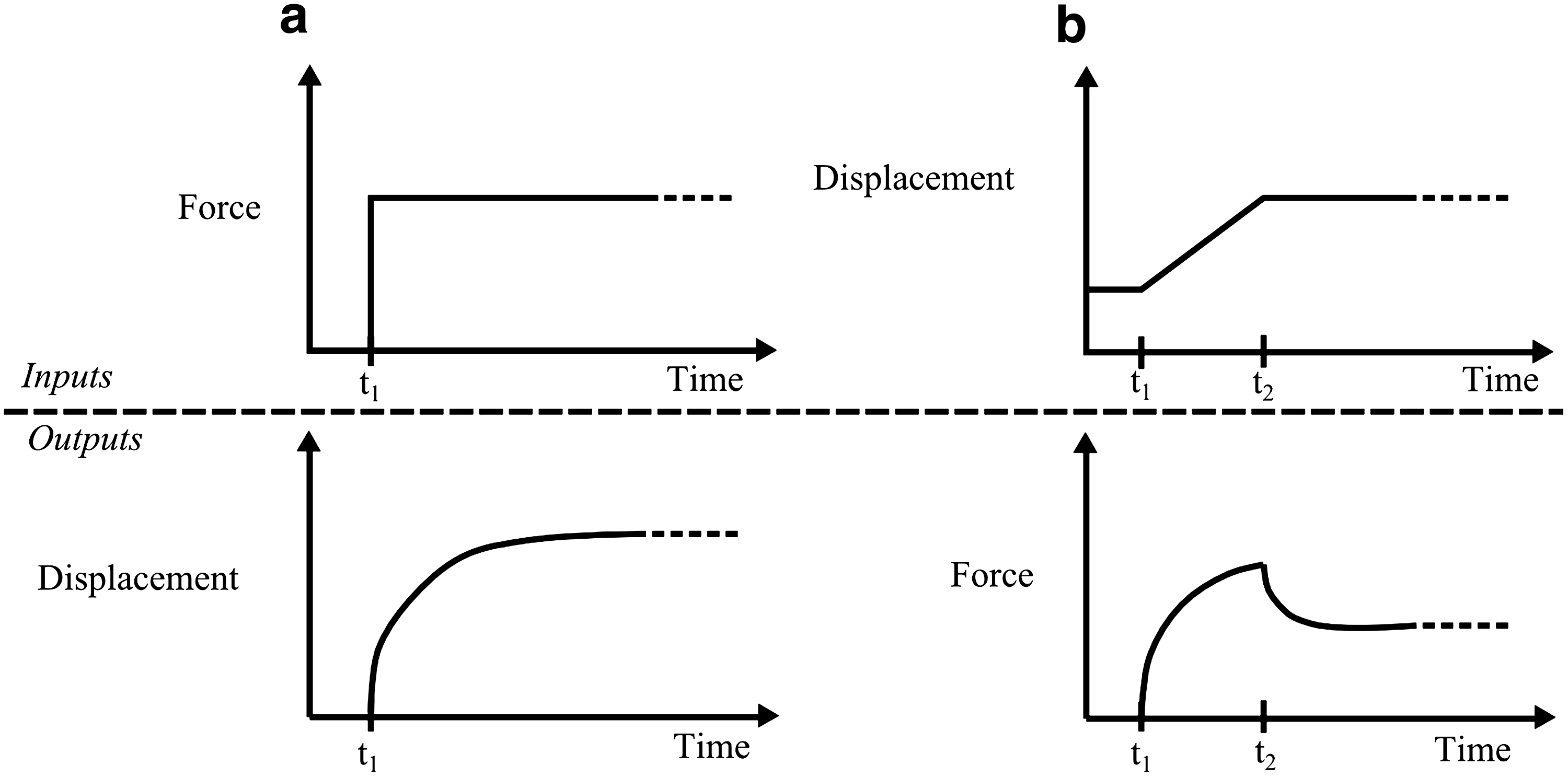
Interstitial water flow through the ECM gives rise to some time-dependent articular cartilage responses. 18 One of these is the displacement response of cartilage to a constant load applied over time, referred to as creep. For example, a creep response following an instantaneous elastic deformation may take ∼1000 s to reach a new equilibrium state. 18 Another response is stress relaxation, which is the force response to a ramped displacement input. The cartilage requires time to react to the applied load or displacement and reach an equilibrium state (Fig. 2). Notably, as the ECM deformation increases, the average ECM pore size decreases, which consequently increases the diffusional drag between the interstitial water and the ECM. 19 As a result, the time to reach the equilibrium state varies depending on the load/displacement applied.
Time-dependent responses of cartilage to
Measuring and characterizing the aforementioned time-dependent or transient responses of native cartilage or ECM, especially in an in vivo environment, is both complex and difficult, and the development of scientific instruments and tools for this purpose faces significant challenges. The mechanical properties of native cartilage or ECM have typically been measured once equilibrium is reached. The equilibrium or time-independent properties of cartilage or ECM include the aggregate modulus, Young's modulus, shear modulus, and Poisson's ratio 20 ; these are discussed in the following section, along with typical testing methods and procedures. To characterize the time-dependent responses or properties of cartilage or ECM, one promising alternative to experimental measurements is the use of mathematical models, which are presented in the Modeling of the Mechanical Properties of Cartilage and TECs section.
Mechanical Properties of Natural Cartilage and TECs and Testing Methods
Three major methods for determining the mechanical properties of articular cartilage and TECs are tensile, compressive, and shear testing. Tensile testing is typically conducted either at equilibrium after a force is applied or at a constant strain rate. The compressive mechanical properties are often measured in three ways: confined compression, indentation, and unconfined compression, Shear properties are normally measured using either a constant displacement to find the equilibrium properties or a sinusoidal displacement to determine the dynamic properties.
To find the tensile equilibrium modulus, a strip of cartilage is subjected to a stress relaxation test (Fig. 3). This procedure subjects the sample to a stepwise series of displacements: at each displacement step, the stress in the cartilage is measured once it reaches its equilibrium value.21,22 The equilibrium stress at each step is then plotted as a function of strain, with the slope giving the tensile equilibrium modulus.
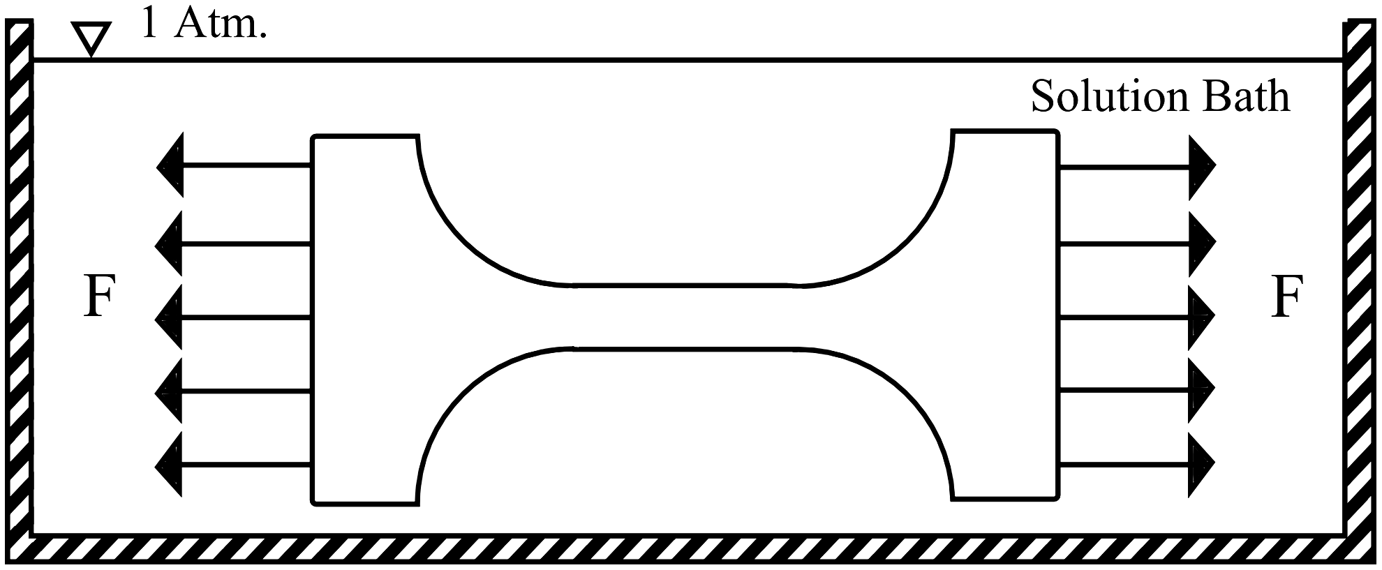
Schematic of the tensile testing apparatus, in which a sample is submerged in a solution (usually phosphate-buffered saline) and subjected to either a tensile force or a tensile strain rate.
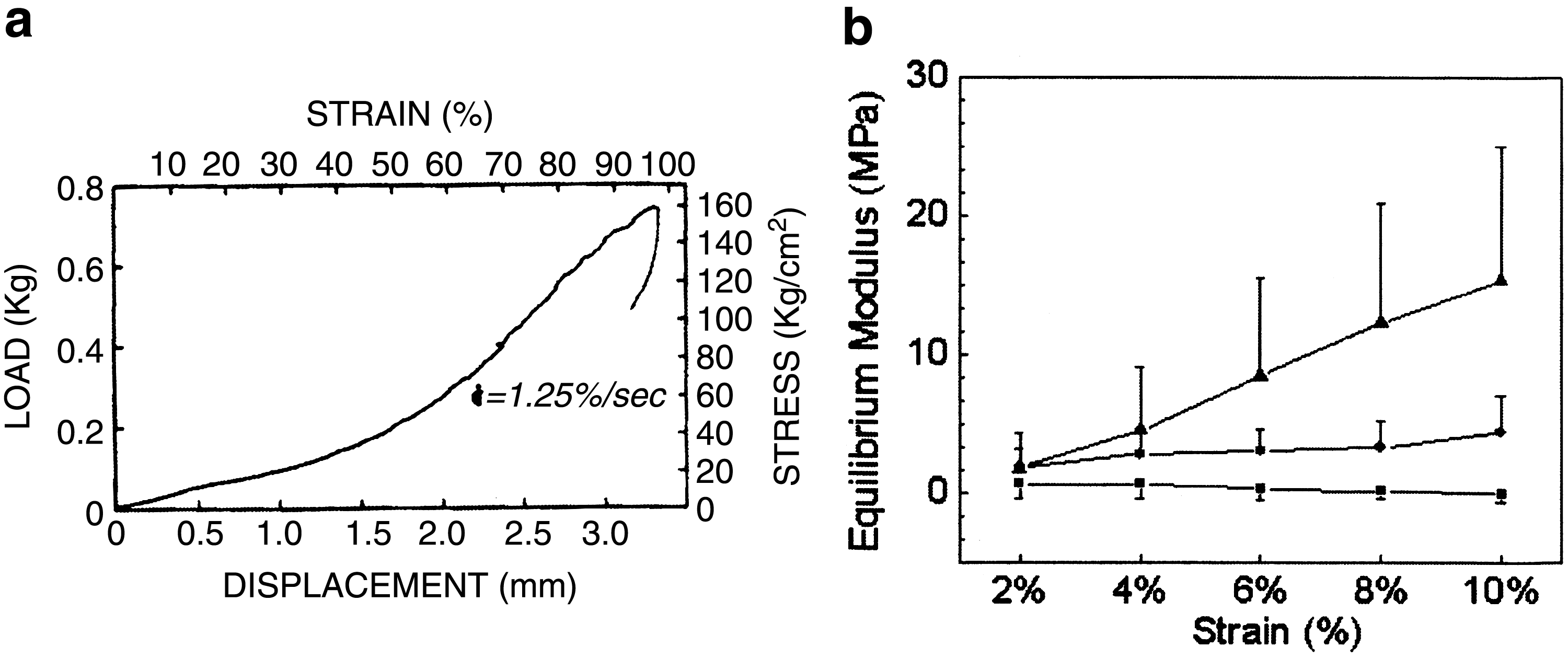
In constant strain rate tensile testing, the sample is subjected to a constant strain rate and the tensile stress is measured at a certain sampling rate. The stress–strain plot of this test reveals a nonlinear “toe-in” region where the collagen bundles are straightening out. Once the bundles are all straightened, the plot enters a near linear region that represents the stretching of these bundles: the data from this linear region can be used to calculate the tensile Young's modulus.20,22,23 Samples used in the tensile tests are typically cut in a dumbbell shape with a thickness of 200–300 μm, and strained at a rate of 5 mm/min.22–26 Depending on the specimen, the stress–strain curves obtained either at equilibrium or under a constant rate of strain may not be linear (Fig. 4a), suggesting that the modulus is not a constant, but a function of strain or stress (Fig. 4b).26,27
Confined compression tests are typically pursued to measure properties such as the hydraulic permeability and the aggregate (equilibrium) modulus of cartilage samples outside of the body (in vitro testing).28–31 Confined compression places a cylindrical cartilage sample into a tube-shaped container with an inner diameter that is ideally the same as the diameter of the sample, to prevent lateral expansion (Fig. 5a). 20 The test subjects the cartilage to a step load and measures displacement as a function of time (creep) (Fig. 2a) or a short ramp displacement with stress measured as a function of time (stress-relaxation) (Figs. 2b and 6). The equilibrium displacement/stress is a function of the cartilage's aggregate modulus. 28 The time it takes for the cartilage to reach the equilibrium displacement/stress is a function of its hydraulic permeability, aggregate modulus, and specimen thickness. A number of factors may affect the measured mechanical properties in these compression tests. First, the cartilage or TEC samples may not conform exactly to the inner diameter of the confined compression chamber, which results in an initial nonlinearity.18,29 Next, the use of a porous piston can increase the tissue resistance during compression, which causes the measured material properties to be different from the true ones.18,29 The friction between the sample and the chamber has also been shown to affect measurements. 32
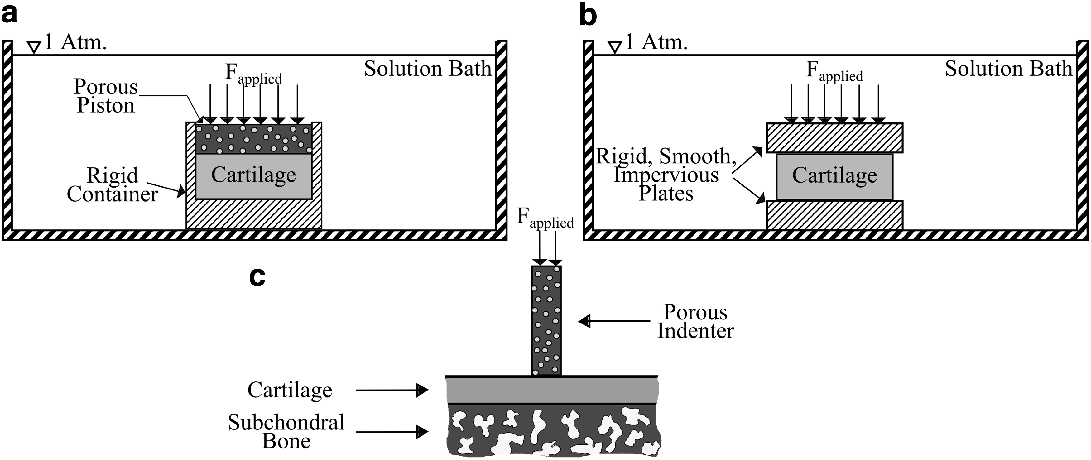
Schematic of types of compressive tests:
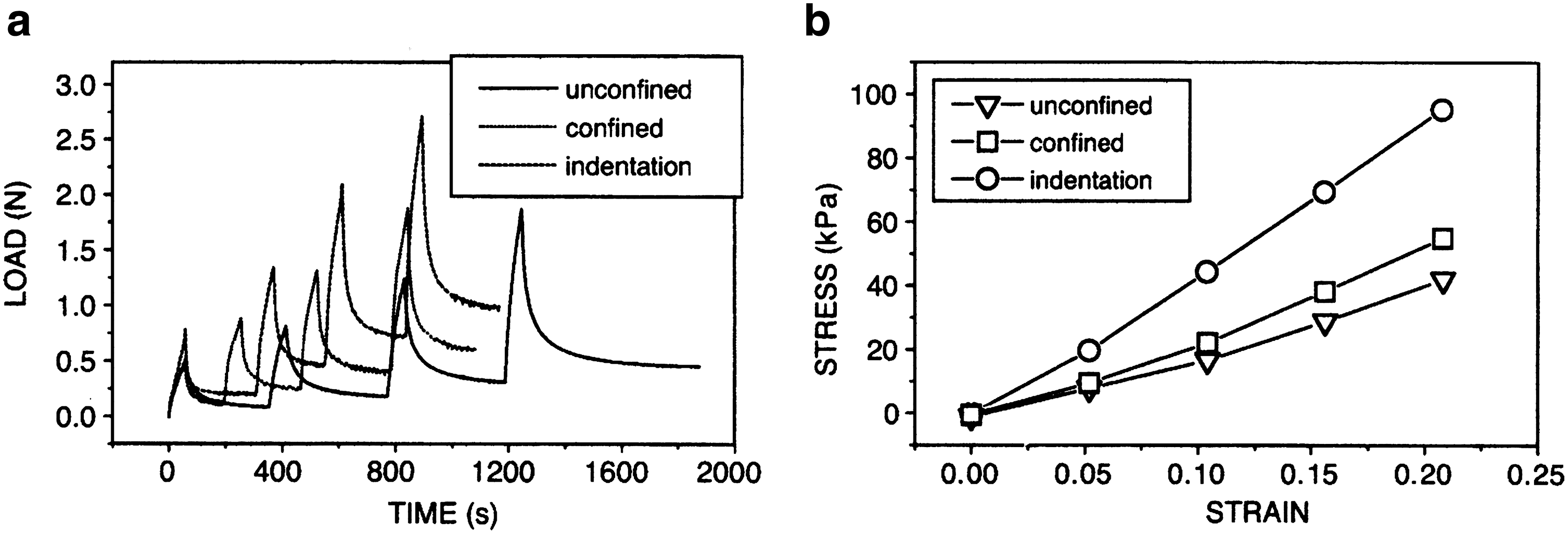
Examples of compression testing data: Data
Another commonly used compression test is indentation.20,34,35 The indentation test (Fig. 5c) is performed with the cartilage still attached to the bone (in situ), which suggests that this method has the potential to be used on living models. In this test, a porous indenter is used to apply a step load to the cartilage and the displacement is measured as a function of time. An a priori model 35 is then used to fit the displacement versus time data by using the nonlinear least squares method. By doing so, parameters such as the aggregate modulus, hydraulic permeability, and Poisson's ratio can be identified or estimated. 20 However, a number of assumptions in the indentation test may not reflect reality; the porous indenter may increase tissue resistance, cartilage permeability is not constant, and cartilage is not homogenous or isotropic.
Before the biphasic theory developed by Mow et al. in 1980, 18 an elastic model was used for fitting the data obtained in the indentation tests 35 in which an approximation of the Poisson's ratio was used to determine the aggregate modulus and hydraulic permeability. Later results from the use of biphasic theory show that the imperfection of Poisson's ratio can result in data off by as much as 200%, 35 suggesting that values of the aggregate modulus and hydraulic permeability from these earlier studies should be viewed with caution.
Unconfined compression tests have not been as widely used as the indentation and confined compression tests. 20 In unconfined tests (Fig. 5b), the cartilage is ideally compressed between two perfectly smooth, rigid, and impervious plates. However, this condition is nearly impossible due to suction between the sample and the plates that causes shear stress. 36 This suction effect can be reduced by applying a lubricant, such as synovial fluid, to the plates. 33 Similar to the other two types of compression tests, the sample is subjected to a step force, whereas the displacement is measured as a function of time. Hydraulic permeability can be measured and characterized similar to confined compression, with interstitial water flowing along the radial direction. 36 Once the sample reaches equilibrium, the compressive Young's modulus and Poisson's ratio of the ECM can be measured and determined. 36
In shear testing, a cylindrical sample of cartilage is subjected to a torsional displacement. For small torsional displacements, both the change in the sample volume and the pressure-driven fluid flow within the cartilage can be ignored, which allows for measurement of the viscoelastic properties of the ECM. 37 In the equilibrium shear test, the sample is subjected to a sudden constant displacement and the shear stress is allowed to reach an equilibrium value. Again, because of the lack of fluid flow, this equilibrium is reached much more quickly (10 s 20 ) than in tensile and compressive tests (1000 s 18 ). This test gives the normalized stress relaxation function, which is a ratio of the instantaneous shear stress to the initial shear stress at t=0+: this is used in the theory of quasilinear viscoelasticity (QLV), as described in the Mathematical Modeling section below, to determine the stresses present in the cartilage as a function of time for a given strain history.20,38 If the sample is subjected to a series of displacements, this test is used to determine the equilibrium shear modulus, which is generally determined by calculating the slope of the equilibrium stress/strain plot (Fig. 7a). While the stress–strain data are highly linear for shear strains of 0.03 and above, they may be better modeled by a quadratic relationship at lower values. 39

The complex (dynamic) shear modulus characterizes the overall stiffness of the ECM under shear stress. This parameter can be measured by subjecting the sample to a sinusoidal strain small enough that fluid flow is not generated (0.00003–0.005).37,40,41 The complex shear modulus has a real portion (i.e., the storage modulus) and an imaginary portion (i.e., the loss modulus) (Fig. 8). 37 The storage modulus is in phase with the sinusoidal displacement and proportional to the amount of strain energy stored in the ECM. The loss modulus, on the other hand, is 90° out of phase with the displacement and proportional to the amount of strain energy dissipated in each cycle. The complex shear modulus is a more appropriate representation of the shear properties actually seen during dynamic activities such as running and walking. 37 Importantly, the complex shear modulus is a frequency-dependent measurement (Fig. 7b), with values of the shear modulus typically reported for given frequencies in the range of 0.01–100 rad/s.41–43
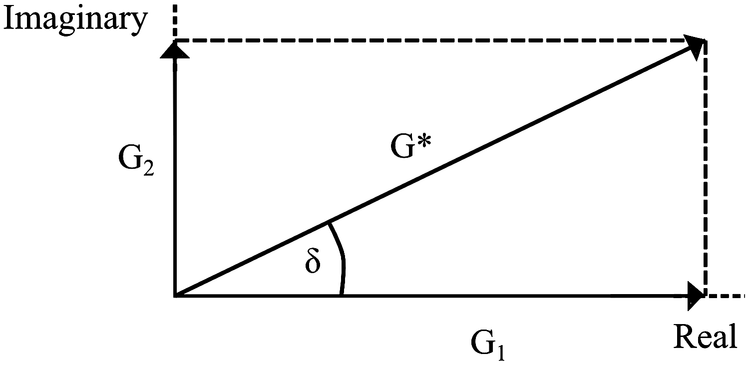
Relationships among the storage modulus (G1), loss modulus (G2), complex shear modulus (G*), and loss angle (δ).
The loss angle (Fig. 8) describes how much of the complex modulus is due to the loss modulus and how much is due to the storage modulus. A loss angle of 90° would describe a completely viscous material, whereas a fully elastic material would have a loss angle of 0°. Materials mainly composed of collagen have a loss angle of about 3.6°, 20 suggesting that collagen behaves in a very elastic manner. PG-rich materials, on the other hand, have a loss angle of ∼70°, 44 suggesting that the PG are largely responsible for the viscous portion of the complex shear modulus of cartilage. Articular cartilage has a loss angle of ∼15°, 19 suggesting that the elastic collagen network provides most of the shear stiffness of ECM.
In the tests described above, choosing appropriate testing conditions such as the force and strain rate applied to the sample is critical, as is determining when the sample has reached equilibrium. These conditions and the equilibrium time will significantly affect the measured material properties. 27 In the literature, the equilibrium criteria are usually defined at specific times39,42 or stress rates,33,45 and thus vary from one study to another. It has been argued 27 that in most of the tests reported in the literature, equilibrium has not actually been achieved. Moreover, a higher strain rate can lead to a higher tensile modulus and an excessively large shear strain may drive fluid flow through the ECM, thus increasing the apparent shear moduli. Therefore, experimental designs based on these testing methods should bear the above in mind and involve a rigorous choice of test parameters.
In addition, the type of test chosen may influence the properties measured. The indentation test yields a higher Young's modulus than the confined and unconfined compression tests, possibly due to the fibrous structure of the tissue being damaged from the sample extraction process in confined/unconfined compression. 33 On the other hand, some material parameters, such as Poisson's ratio, appear to be independent of the test method used. 46
By means of the aforementioned methods, the mechanical properties of articular cartilage and TECs have been extensively investigated. Typical values of the measured mechanical properties are summarized in Table 1. For most entries, values are given within a range; this is due to the variation in the mechanical properties in different joint locations, 35 donor species, and donor ages. 22
CC, confined compression; UC, unconfined compression; I, indentation; TSR, tensile stress relaxation; TCSR, tensile constant strain rate; ES, equilibrium shear; DS, dynamic shear; TEC, tissue-engineered construct; ECM, extracellular matrix.
Mechanical properties such as the equilibrium shear modulus, Poisson's ratio, and aggregate modulus vary significantly for different joint locations.20,41,51,53 Some recent research shows that mechanical properties even differ significantly between surfaces that articulate against one another. 22 This mechanical discrepancy between articulating surfaces may contribute to cartilage degradation. 53 Notably, some properties, such as the tensile Young's modulus, are very sensitive to the anisotropies present in the cartilage. In one study, 10 the tensile Young's modulus depended not only on the zone from which the sample was taken from, but also on the orientation of the sample. For example, a sample taken parallel to the split line* leads to a higher Young's modulus than a sample taken perpendicular to the split line. Further, a sample taken from the deep or middle zone has a lower tensile modulus than one from the superficial zone. In addition to joint location, orientation, and depth, donor species also affects the measured mechanical properties. An examination of cartilage samples from human, bovine, canine, monkey, and rabbit donors indicates that the hydraulic permeability and Poisson's ratio are significantly different, but the aggregate modulus is quite similar. 54 Finally, donor age will affect the measured properties, which tend to increase into adulthood, and then decrease with old age.10,22,23,27,28
Modeling of the Mechanical Properties of Cartilage and TECs
An emerging method that may provide an alternative to mechanical testing of cartilage tissue and TECs is mathematical modeling. The primary advantage of mathematical modeling over experimental methods in TEC design is their ability, once validated by experiments, to predict the behavior of candidate TEC designs. This allows the optimum design to be identified without the need for extensive experimental investigations. Another unique advantage of mathematical models is that they can be developed and used to derive or estimate the mechanical properties of individual material phases within the cartilage based on the measured bulk behavior. The progression of many diseases of cartilage results in the changes in mechanical properties. 55 As such, a sequential examination of this change can provide information on the progression of the disease and may lead to the identification of the primary mechanisms of age-related cartilage degeneration. Experimental methods, however, only give the bulk or average properties of the cartilage, rather than the specific mechanical properties of local tissues. One possible experimental approach to this problem is the use of histology combined with micro- and even nanoindentation to measure the 3D distribution of mechanical properties in the tissue. However, in addition the problems of cutting-induced deformation from this approach, even nanoindentation may be unable to directly measure the properties of the individual phases within the cartilage tissue. Another way to estimate the properties of the individual phases within tissue would be to measure of the bulk properties of the tissue at specific locations, and then from these measurements derive the mechanical properties of each individual material phase within the tissue from a mathematical model.
A TEC for cartilage repair is generally composed of three primary material phases: (1) a biodegradable framework or scaffold designed to persist briefly in the body before biological degradation; (2) cartilage tissue that has taken up residence inside the porous scaffold framework; and (3) fluid filled space. The mechanical properties of each of these individual phases and their volume fraction of within the TEC contribute to the effective mechanical behavior of the three-phase mixture. As an added complexity, the cartilage tissue component of this mixture is itself a complex composite material. A full theoretical treatment of the effective mechanical properties of TECs should first include the development of mechanical models for each of the constituent phases in the system. The resultant models should ideally represent the strain rate-dependent deformation of the phases in tension and compression for small and large deformations, and also include the time-dependent creep behavior of the material phases of the TEC in tension and compression. These models are then applied in a homogenization scheme to give the effective properties of the mixture.
The tissue scaffold component of the TEC is typically composed of synthetic biodegradable polymers that are either amorphous or semicrystalline. The stress–strain behavior of this kind of material under varying strain rates can be represented using models based on the networks of spring and damper elements (Fig. 9). 56 Based on such a model, the strain rate-dependent behavior of the polymeric scaffold material can be determined (Fig. 10).
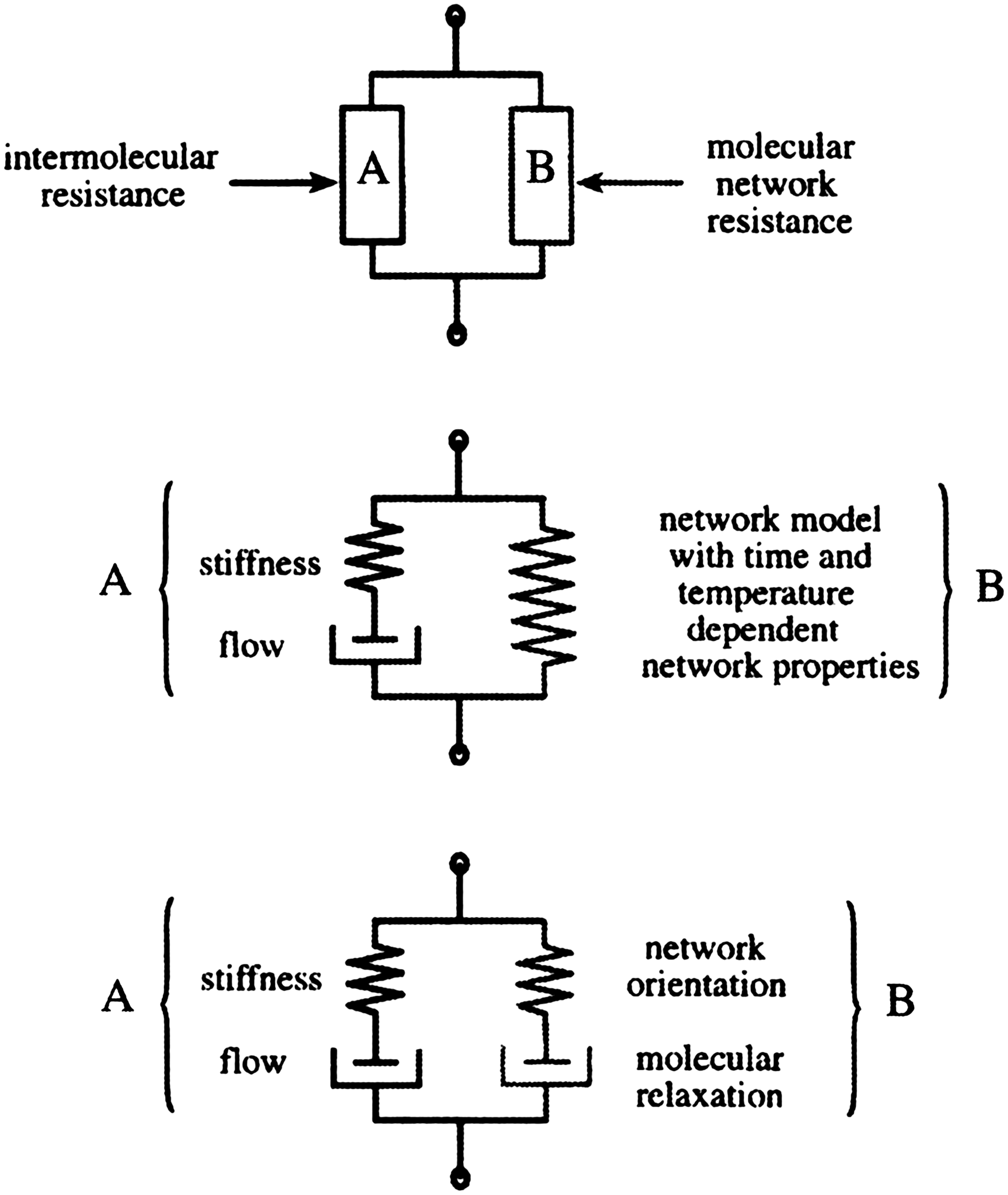
Spring-dashpot networks representing resistance of the polymer to strain as an intermolecular resistance to deformation as well as resistance from molecular network reorientation (reprinted from Ref. 56 with permission from Elsevier).

Stress–strain curves of polymers at different strain rates (reprinted from Ref. 56 with permission from Elsevier).
The next material phase in the TEC is the tissue cartilage itself. Many different approaches have been proposed to represent mathematically the behavior of tissue cartilage. In one approach, 57 the cartilage is modeled as a network of spring elements representing the fibrils prestressed by osmotic pressure. The Donnan osmotic pressure of the tissue is considered as a function of the tissue outer geometry, which can be altered to reflect its variation in a confined compression test. This model shows promise for reproducing the experimentally observed behavior of cartilage at a specific strain rate. Further development or modification of these existing models to include the strain rate-dependency of the fibril network is urged.
Because cartilage shares similarities with moistened soil, poroelastic models developed for the analysis of soils offer another possible avenue for the modeling of cartilage tissue. In one approach, 58 the poroelastic soil analysis elements present in the commercial software ABAQUS were employed to model the mechanical behavior of a cartilage tissue plug in confined compression. The results obtained were compared to a mechanical model based on a biphasic rule of mixtures (detailed below) and close agreement was found. In another study, 59 ABAQUS was employed to model cartilage tissue behavior under compression, with agreement found between the experimental results and model predictions.
Another model commonly employed to represent the load–deformation behavior of cartilage is the biphasic model based on the rule of mixtures, which represents cartilage tissue as a linear elastic or nonlinear viscoelastic matrix infused with an incompressible fluid phase. The governing equations for this model are the conservation of mass and momentum laws for a two phase liquid–solid mixture.
60
The conservation of mass for the solid fluid mixture is given by
where u is the displacement of the solid phase and
where τ is the effective stress tensor of the mixture,
where τs is the stress tensor for the solid phase and τw the stress tensor for the liquid phase of the tissue. In addition, the stress in the fluid phase can be represented as
where p is the pore pressure, ϕ the porosity of the tissue, and I the identity matrix. Further, the velocity of the fluid phase with respect to the solid phase may be related to the acceleration of the solid phase by
where k is the hydraulic conductivity (permeability) matrix of the solid phase p the pore pressure distribution within the tissue, g the acceleration due to gravity, and g the gravity acceleration vector. The above governing equations may be solved using the finite element method. After being placed into the finite element matrix form, a Newmark-based numerical integration scheme can be employed 60 to solve the governing Equations (3)–(5) and estimate the nodal displacements of the solid phase and the nodal pore pressure distribution within the saturated solid body. While the above formulation assumes a linear elastic solid phase and an incompressible fluid phase with small deformations, this approach 60 also results in a large deformation finite element formulation for the conservation of mass and momentum when the solid phase is assumed to be compressible and hyperelastic. A further development is the triphasic model of cartilage, which divides the liquid phase further into two separate fluids, that is, intrafibrillar and extrafibrillar fluid phases. The intrafibrillar fluid phase contains intrafibrillar water, sodium ions, and chloride ions; the extrafibrillar fluid phase includes PG, extrafibrillar water, and sodium and chloride ions. 61 This model gave predictions in agreement with experimental results from confined compression tests. 61
Another approach
62
presents a generalized n+2 phase theory for charged hydrated tissue. The charged and hydrated tissue is modeled as a continuum of three phases, that is, solid phase, solvent phase, and n ion phases or species dissolved in the solvent. The solid phase and ions are assumed to carry charge, whereas the solvent phase is neutral. The continuity equation for such a system is given by
where
where ρ is the density of each phase,
Another mathematical model developed to represent the constitutive behavior of cartilage tissue in both tension and compression is based on the theory of QLV proposed by Fung.
38
This model represents tissue as a homogenous rheological fluid, where the stress in the body with time σ(t) is given as function of the stretch ratio λ(t),
63
where Ts(λ) is elastic stress as a function of the stretch ratio and G(t) the ratio of current stress to the elastic instantaneous stress present immediately after load application, which is given by
The stress response of the system to an infinitesimal change in stretch when the object is initially in the state of stretch λ at the time τ is given by
where σ(t) is the first Piola-Kirchhoff stress as a function of time, which is evaluated from the forces in the deformed configuration of a body and the areas present in the original reference configuration of the body. The stress history in the body with time is given by the time integral of Equation (10), that is,
where Ss is the stress from the instantaneous nonlinear equilibrium response of the tissue, G the reduced relaxation function,
where α, t, and τ are the material property parameters that can be estimated from a stress relaxation test.
64
The instantaneous stress relaxation of the tissue in compression or tension is experimentally determined, typically taking the form of
where ɛ is strain (stretch ratio) and E(ɛ) a nonlinear function for compressive and tensile loading determined from the initial behavior of a tissue sample under compression or tension. The above model was used to represent the tensile response of cartilage tissue, dominated by the viscoelastic behavior of the cartilage solid matrix. 64 Under compression, the viscoelasticity of the tissue is fluid-flow dependent and is modeled by using a relaxation function to account for the effect of fluid flow on the cartilage. Because this modeling method represents the cartilage as a homogeneous solid, the resultant QLV model cannot represent the material properties of individual constituents within cartilage. If a TEC is considered, however, this method would be used to estimate the mechanical properties of the regenerating tissue within the scaffold from the measurements of the effective properties of the TEC. This is an inverse problem, where the known effective properties of the TEC are functions of the unknown properties of its constituents. The QLV model can be incorporated into biphasic theory to give a more accurate representation of the behavior of the cartilage matrix, which is assumed in classical biphasic theory to be only a simple linear elastic material. 65
With the availability of models for both the cartilage tissue and solid scaffold material phases, the next step in modeling the TEC's effective mechanical properties is to combine the material models based on the homogenization method. Considering a representative piece of the TEC, with strain-dependent stress–strain curves for each material phase, finite element models of the TEC can be constructed and subjected to displacement boundary conditions that simulate the effect of a mechanical test. For cases with large displacements, nonlinear material behavior, and/or strain rate dependence, the nonlinear problem can be linearized by applying the prescribed displacement boundary conditions as step loads and/or updating the modulus of material at the experienced strain level in each of the finite elements. During each step, the configuration of the nodes from the previous step is employed to assemble a linear stiffness matrix, and the strain in each element, determined in the previous load step, is employed to select an appropriate stiffness for each element in the body from the known stress–strain curves of the constituents. This approach may be executed using commercial software, such as ANSYS. Unfortunately, representation of the full TEC in a finite element model is a significant computational burden. An alternative is the use of a small representative piece of the TEC, which is known as a representative volume (RV). This is accomplished based on the homogenization method, in which a TEC is represented by a finite number of RVs that possess location-independent mechanical properties. A type of traction or deflection boundary condition is then applied to the RV such that the average stress within the body is an average of the stress distribution experienced by all of the assembled cells in the complete TEC. To effectively represent RV deformation in the presence of neighboring cells, the deformation pattern of the RV's outer surface should be some type of average of the deformation shape experienced by all the unit cells in the TEC. One deflection boundary condition to achieve this objective is the periodic deflection boundary condition, where the displacements on opposite sides of the RV tile together. These displacement boundary conditions are represented mathematically as
66
where ui is the displacement of a node on the boundary of the RV,
where K+ indicates the positive xj direction and K− the negative xj direction. The difference between the deflections on opposite sides of the RV is therefore given by
If the TEC considered is heterogeneous, the strategy of using averaged properties can be applied and expressed mathematically by
where Sij Tij are the strain and stress, respectively, and the over-bar indicates a volume average.
Representing or modeling the displacement-under-loading behavior of hydrated tissues such as cartilage by solving the governing equations in the above shows promise. Constitutive relations for all of the material phases within the TEC can be incorporated into finite element models of the TEC to predict its mechanical behavior. The primary source of error in such models is considered to mainly come from the assumption of homogenization in each structural level of the TEC. With the advance of computing technologies, future work should include more structural details in finite element models of the TEC to release or partially release the homogenization assumption of the TEC structure.
Methods to Enhance the Mechanical Properties of TECs
The mechanical properties of TECs for cartilage repair should match those of native articular cartilage. As discussed above, the mechanical properties of cartilage vary widely and depend on donor species and age, as well as joint location and sample orientation. As such, the mechanical properties of TECs should be defined and determined differently for specific implantation sites. To make things more challenging, the TEC's mechanical properties are not constant during the healing process, but change dynamically with time as the tissue regenerates and the scaffold degrades. Thus, engineering functional cartilage with matching mechanical properties has proven to be extremely difficult and, so far, engineered cartilage has largely been mechanically inferior to native cartilage.43,67–69 A number of methods or techniques have been developed to enhance the mechanical properties of engineered cartilage, including control over the amount of ECM components that the chondrocytes produce, control over the fiber geometry within the scaffolds, and selection of scaffold materials with appropriate mechanical properties.
By modifying the amount of ECM components, that is, PG and collagen, that the chondrocytes produce, the mechanical properties of the cartilage can be controlled. For example, the shear storage and tensile modulus can be enhanced by increasing collagen concentrations or the cross-linking of the collagen fibrils.37,70 On the other hand, decreasing the PG concentrations within the ECM can reduce the tensile and compressive moduli by 10-fold.20,37 One method for controlling collagen and PG levels within the ECM is the use of mechanical stimulation, such as hydrostatic pressure 71 and dynamic shear or compression. 72 The levels of PG and collagen vary, depending on the type of loading regimen, 71 for example, if the loading frequency is low (0.3 Hz) or high (3 Hz), ECM production can be inhibited, with 1 Hz appearing optimal for ECM production.45,73,74 The compression amplitude can also regulate both PG and collagen synthesis. 45 These findings have been recently applied to bioreactor design, so that they are able to mimic the dynamic forces seen in the native joints and thereby create cartilage with similar mechanical properties. 75 By altering the flow conditions within the bioreactor, one can adjust the mechanical properties and possibly improve the mechanical properties of TECs.30,69 In the aforementioned processes, the interactions between cells and ECM play a critical role. These interactions, however, are complicated and many remain to be defined. In addition to experimental methods, the use of finite element methods would be a powerful tool to discover links between mechanical stimulation and cellular activity. 76
Another method of adjusting the levels of PG and collagens is the use of chemical stimulants, the most common of which is fetal bovine serum (FBS). FBS is a pathological fluid formed in response to blood clotting and is a combination of many chemical stimulants. When added to cell culture, FBS increases cell proliferation and ECM production. 77 However, one large drawback is that this serum has a poorly defined composition, which can lead to problems with growing tissue in a repeatable manner. 78 Recent studies have used other individual stimulants, such as bone morphogenetic proteins and transforming growth factors,79–83 that have a more defined composition and give more repeatable results. In addition, natural cartilage ECM components such as HA and chondroitin sulfate can mechanically enhance TECs. The addition of HA to a cell medium or hydrogel enhances the production of GAGs and collagen II as well as significantly increases cell proliferation 84,85; the addition of chondroitin sulfate increases cell proliferation and PG synthesis.86,87 However, these individual stimulants are relatively costly and have problems, including retention them within the TECs. 88
The mechanical properties of TECs can also be controlled via the design of scaffolds for the repair of cartilage. Increasing scaffold porosity would increase the loss angle and plastic deformation and decreases the storage modulus and aggregate modulus. 48 Changing the strand orientation within the scaffold, for example, from a 0–90 to a 0–45 pattern (Fig. 11), or using different types of honeycomb structures can significantly alter the mechanical properties.48,89 Another important consideration is the biological properties of the scaffold. Pore size cannot be made arbitrarily small for maximizing the aggregate modulus because a certain pore size and porosity is necessary to allow for cell delivery and tissue ingrowth. Mathematical models may allow one to optimize the trade-off between tissue growth and porosity before even entering the laboratory. 90
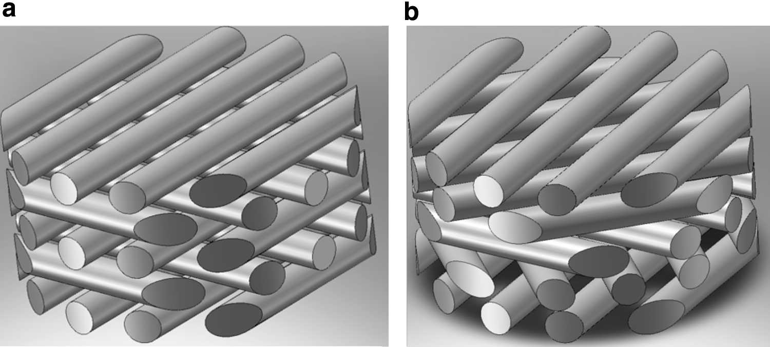
Schematic showing the strand orientation for the 0–90
Different scaffold materials are recognized as having different mechanical and biological properties. These distinct yet diverse properties can be used to control and ensure the mechanical properties of the TEC. For example, a scaffold made out of poly(glycolic acid) is stiffer than one with an identical geometry made of poly(lactic acid). 91 Different materials also differentially stimulate chondrocytes. For example, a poly(glycolic acid) scaffold stimulates PG synthesis, whereas a collagen scaffold stimulates collagen II synthesis. 92 Further developments or investigations are urged to strategically combine different materials in scaffold designs to achieve synergistic properties of scaffolds.
Future Research Work
An initial goal of cartilage tissue engineering was to create a homogeneous tissue with the same bulk properties as the surrounding tissue. 93 However, current research has focused on creating mechanical property gradients within the TECs to more closely mimic the four zones found in native cartilage. The potential for stratification has been demonstrated through the creation of pore size, porosity, and stiffness gradients 9 within fabricated scaffolds. Recently, layered TECs were shown to reduce strain discontinuities between the TEC and the surrounding natural cartilage, 94 demonstrating their promise for achieving mechanical property gradients within TECs. Hydrogels are well known for their biocompatibility and recently have been demonstrated as suitable for creating such layered scaffolds. Moreover, chondrocytes can be isolated from the different zones of native cartilage and cultured separately. These different cells can then be encapsulated in separate hydrogel disks. Eventually, these disks can be layered on top of one another to produce a stratified culture, 95 with the construct producing a smooth transition between the layers with time. 96 These constructs also have the potential to create layers with differing chemical stimulants and/or mechanical properties. One promising research avenue for the creation of stratified TECs is the development of a hybrid scaffold that incorporates the “cell friendly” environment of a hydrogel with the mechanical stability of a solid polymer scaffold. Control of the mechanical properties of these scaffolds would be easier than with hydrogels alone, and includes the opportunity to create different hydrogel layers (as discussed above) within the solid scaffold. Preliminary studies of these hybrid scaffolds have shown promising results. 97 More experiments will be needed with different types of cell stimulation and scaffold design before TECs are created with the desired bulk and local mechanical properties of natural articular cartilage.
To design TECs with the desired mechanical properties gradients, an alternative method to the experimental methods is the use of mathematical models. Mathematical models, including one based on modeling updating, 98 have been developed to predict the time-dependent mechanical properties. Some mathematical models of the behavior of cartilage tissue give good predictions of experimental tissue behavior. The last component necessary for the complete mathematical analysis of cartilage TEC mechanical properties and their time-dependent evolution is a model that can describe the time-dependent regeneration and behavior of tissue within the TEC. 99 If such models can be improved to more accurately represent the strain-dependent mechanical properties of tissue/scaffold under compression and tension, and the gradual change in tissue/scaffold composition during scaffold degradation and tissue regeneration, they will provide an effective means to mathematically evaluate TEC designs and optimize their performance. This will require determining or modeling various interrelationships within the scaffold, such as the effects of living tissue and scaffold degradation products on the degradation rate of the solid scaffold.
As cartilage tissue engineering moves toward implanting TECs to repair damaged cartilage in human patients, noninvasive methods of testing the properties of the implanted TECs in situ must be developed. The only one of the aforementioned methods currently capable of testing implanted TECs in situ is indentation, and even this method would require surgery. To track the properties of TECs after implantation, imaging methods such as magnetic resonance imaging 17 show the most promise. Typically, image-based methods are based on the idea of measuring the strain in the cartilage before and after loading in a joint and using these measurements to determine the aforementioned mechanical properties. These imaging methods will help researchers determine the success of TEC implants without subjecting the patient to another surgery.
Conclusions
Cartilage tissue engineering has made great strides toward growing cartilage substitutes with the mechanical properties necessary to withstand the loads found within joints. Mathematical modeling, in conjunction with tensile, compressive, and shear testing, provides researchers with the mechanical properties that govern both the equilibrium and the transient responses, and allows the accurate comparison of TECs to natural cartilage.
Although current TECs have, for the most part, not achieved mechanical properties that match those of natural cartilage, considerable progress has been made in the development of methods to modify the mechanical properties of TECs. These methods include modifying the amount of ECM components produced by chondrocytes through mechanical or chemical stimulation, adjusting the internal scaffold structure, and choosing appropriate scaffold materials or their combinations. Further work or development to create stratified cartilage and mathematically model the time-dependent properties of TECs is encouraged to achieve mechanical property gradients within the TECs to mimic the four zones found in native cartilage.
Footnotes
Acknowledgments
The authors would like to acknowledge financial support from the Natural Sciences and Engineering Research Council of Canada (NSERC) and the Saskatchewan Health Research Foundation (SHRF).
Disclosure Statement
No competing financial interests exist for any of the authors.
*
The split lines mentioned above are presumed to be indicators of the direction of the collagen fibres in the superficial layer [12] and can be determined by puncturing the cartilage with a circular awl. The resulting holes are “stretched out,” or elliptical, and the major axis of the ellipse is known as the split line direction [37].