
Abstract
In this work we propose a new method titled “layered hydrospinning.” In this method, nanofibers are being collected on top of a liquid reservoir and assembled layer-by-layer to form a 3D scaffold. The geometrical features of fabricated hydrospun scaffolds show a porosity of 99% and pores of a diameter over 100 μm. Cells were seeded during the hydrospinning process, thus achieving an initial even density of cells in the scaffold. We show that human embryonic stem cells and mouse myoblasts cultured on the scaffolds were able to infiltrate further into the scaffolds and proliferate to a greater extent, compared to conventional electrospun scaffolds collected on a plate.
Introduction
One of the methods used to create scaffolds is electrospinning.8,9 In the process of electrospinning, polymer solution is injected through a syringe. A drop is created at the tip of the needle, and a high voltage is then applied to the needle, so that a large potential difference is created between the tip of the needle and the grounded collector. The potential difference causes the drop of solution to rapidly elongate toward the collector. The final result is a nanofiber that is deposited on a solid collector, usually a conducting plate. The fiber diameter can range from 10 to 10,000 nm, correspondingly with the rheological properties of the polymer solution, its flow rate, and the strength of the applied electrostatic field.5,10,11 In the collection process, a nonwoven mat is created, which makes a 3D scaffold for the cells and is highly bio-compatible, largely because of the large surface area the nanofibers present to the cells. Cells growing on a nanofibrous mat have been shown to exhibit higher attachment and proliferation than cells growing on a smooth or microfibrous mat. 12 In general, nanoscale architectures make the cell to create more filopodia (its sensing organelles) 13 and add to the proliferation and attachment ability of the cell. Although the electrospun scaffold can be made highly porous and biocompatible, it severely lacks in permeability. 14 Another problem with electrospinning is the extremely slow rate of nanofibrous scaffold creation, which makes electrospinning as a method suitable only for extremely thin scaffolds.
Many subtle variations of electrospinning have been devised, in order to create large pores in electrospun nanofibrous scaffolds and raise their permeability. Those variations include salt leaching, 15 the addition of a chemical blowing agent to the scaffold 16 and even laser ablation. 17 The first two methods require exposure of the scaffold to temperatures of 45–100°C, which causes a partial sintering and melting of the nanofibrous scaffold. One should note that in both cases the infiltration of the cells beyond the space created by the pores was unremarkable. The third method has its limitations, especially concerning the interconnectivity of the created pores.
In this work we suggest an alternative approach to electrospinning, titled “layered hydrospinning.” In a layered (or layer-by-layer) hydrospinning, nanofibrous scaffolds that contain many separable layers are created, with extremely large pores between them. Those scaffolds exhibit a porosity of up to 99% and pores with a diameter of over 100 μm. Another important characteristic of this novel method is that extremely thick scaffolds—exhibiting a thickness of more than 1 cm—can be attained in a relatively short period of spinning.
In this report we describe the layered hydrospinning method, which we deployed to create two different kinds of scaffolds—microfibrous and nanofibrous. Myoblasts and human embryonic stem cells (hESCs) were seeded onto the finished scaffolds, and their density was measured, quantified, and compared to the cellular density found in the controls—traditionally electrospun scaffolds. Furthermore, the feasibility and ease of cell seeding during the layered-hydrospinning process were demonstrated.
Materials and Methods
Preparation of the scaffolds
Layered hydrospinning
In a layer-by-layer hydrospinning, the nanofibers are spun onto a water coagulation bath instead of a collection plate. Such a coagulation was previously incorporated into the electrospinning process by Srinivasan and Reneker 18 and Kim et al 19 Smit et al. have shown that the nanofibers can be collected from the surface of the bath, 20 and Teo et al. perfected that idea in order to create an aligned yarn. 21 The coagulation bath initiates a formation of skin around the nanofibers, and thus prevents them from fusing into each other during the collection process. 22
In this work, the nanofibers were collected on the surface of the liquid, where a thin layer was rapidly formed, and was kept afloat. This thin layer was picked from the surface of the liquid on a glass in certain time intervals, eventually creating a hydrospun scaffold composed of many nanofibrous layers (see Fig. 1). Since each layer was wider than the slide, the extra fabric dangled from both sides of the slide and was drawn to the bottom of the slide, preventing the layer from drifting away when the slide was put back into the coagulation bath.

The method of layered hydrospinning. (
Two different kinds of scaffolds were created in this method, differing from each other by the diameter of the nanofibers and the number of layers collected. In the first scaffold created (hydrospun-microfibrous), the materials for the hydrospinning included a 15% solution of poly(caprolactone) (PCL, Mw 80,000; Aldrich, St. Louis, MO) prepared in a 75:25 wt. mixture of dichloromethane (DCM) (Frutarom, Haifa, Israel) and dimethylformamide (DMF) (Frutarom), and hydrospun at 18.06 kV, using a DC power supply (Glassman High Voltage Ltd., High Bridge, NJ). The distance from the end of the 21G needle to the collector was 32.5 cm, and the flow rate was set at 20 mL/h. The nanofibrous layer was collected from the liquid surface every 10 s. The second type of scaffold (hydrospun-nanofibrous) was created from a 10% solution of PCL in the same mixture of 75:25 DCM/DMF, which hydrospun at a 13 kV voltage, with a 25G needle at a height of 20 cm from the liquid surface. The flow rate was set at 1.2 mL/h. The nanofibrous layer was collected from the liquid surface every 60 s. The coagulation bath was filled with distilled water at room temperature with a 1.25 g/L concentration of sodium chloride (NaCl). Both the above scaffolds were desiccated in a vacuum environment (20 mbar) for 2 days.
Electrospinning
Using the previous parameters, two scaffolds were electrospun, using a flat collecting electrode, covered with aluminum-foil, to collect the nanofibers. The first scaffold (15% PCL in 75:25 DCM/DMF, 18.06 kV, 32.5 cm height, 20 mL/h, and 21G needle) has been termed the electrospun-microfibers. The second scaffold (10% PCL in 75:25 DCM/DMF, 13 kV, 20 cm height, 1.2 mL/h, and 25G needle) has been termed the electrospun-nanofibrous scaffold. The two constructs were desiccated in a vacuum environment (20 mbar) for 2 days.
Properties of the scaffolds
Fiber diameter and pore size measurement
Following desiccation of the scaffolds, they were sputter-coated with gold (Polaron Equipment, East Sussex, UK, E5150, SEM Coating Unit) and observed using the HR-SEM (HR-SEM, LEO 982) at an accelerating voltage of 3 or 4 kV. The images were analyzed using SemAfore (SemAfore Version 4.01), and the fiber diameter and pore diameter were recorded. To minimize bias when choosing which pores to measure, we drew a line from the upper-right corner of each image to the lower-left corner, and counted only the pores through which this line passed. The pore diameter was deduced from the average diameter of an inscribed circle enclosed between the fibers.
Porosity measurement
The porosity of the scaffold was determined via gravitometric measurements. The geometry of the scaffold was measured using a caliper. By weighing the scaffold, we could determine its mass and then the porosity (P) of the scaffold, P = 1 − (ρscaffold/ρPCL). Where ρPCL is the density of the PCL.
Scaffold buildup rate
To quantify and standardize the fabricated scaffold's volume in relation to the spinning time, we employ the scaffold buildup rate (SBR) relation,
Cell seeding on the scaffolds
Cell seeding during layered hydrospinning
Using the previous parameters, a microfibrous scaffold was hydrospun into a phosphate buffered saline (PBS) coagulation bath. The hydrospinning was performed in a clean environment, but due to technical difficulties, no sterilization was performed. As compensation, the PBS coagulation bath contained 1% penstrep antibiotic. During the spinning, 100 layers were picked up from the surface of the water and placed on top of each other. Mouse myoblasts were seeded upon each layer before the next layer was stretched onto it. On each layer, 10,000 cells were seeded in a specific location. When 100 layers were obtained, the scaffold was cut and put into a six-well plate, and a minimal amount of growth medium was added to prevent cellular death. After 30 min, 5 mL of growth medium was added to the well. The scaffold was incubated for 4 days, and the medium was replaced every day. This scaffold has been termed hydroseeded-microfibers.
Sterilization of scaffolds
The unseeded scaffolds were cut out of the mat using a hole puncher. The radius of the created scaffolds was 0.4 cm. The hydrospun-nanofibrous and electrospun-nanofibrous scaffolds were sterilized by an immersion overnight in a 70% ethanol (Ethanol Absolute; Bio Lab, Jerusalem, Israel, 556511) solution. Any NaCl caught in the scaffold should have been washed away during the immersion period. The scaffolds were checked every 2 days throughout the experiment to make sure that they were not contaminated. An alternative method used for sterilization of the hydrospun-microfibrous and electrospun-microfibrous scaffolds was plasma in a DEKAM device, at 200 RF for 30 s.
Maintenance of cells
hES cells (H9 clone) were grown on mouse embryonic fibroblasts in knockout medium composed of 15% Knockout SR (Knockout SR; Gibco, Carlsbad, CA 314796), 1% nonessential amino acids (MEM NEAA; Gibco, 301597), 100 mM L-glutamine (L-glutamine 200 mM; Gibco, 9825), 0.1 mM β-mercaptoethanol (2-mercaptoethanol 50MM; Gibco, 208665), 4 ng/mL bFGF (Invitrogen, 13256-029), and 85% knockout D-MEM (Knockout DMEM; Gibco, 307381). Tissue culture plates were coated with 0.1% gelatin (Sigma). Cultures were grown in 5% CO2 and were routinely passaged every 5–6 days after disaggregating with 1 mg/mL collagenase type IV (GIBCO/BRL, St. Louis, MO). To induce formation of embryonic bodies (EBs), human embryonic stem (hES) colonies were digested by using 1 mg/mL collagenase type IV, and transferred to Petri dishes to allow their aggregation and prevent adherence to the plate. Human EBs were grown in the same culture medium without basic fibroblast growth factor (bFGF). Mouse skeletal myoblast cells (C2), a gift from Prof. David Yaffe (Weitzman Institute), were maintained in a culture medium composed of 20% fetal bovine serum (Hyclone, CPL0252), 1% Penstrep (Pen-strep solution; Biological Industries, Beit Haemek, Israel, 652564), 2.5% HEPES (HEPES buffered saline solution; Clonetics, 01114089), and 76.5% D-MEM (DMEM; Gibco, 253810). The cells were harvested using 2 mL Trypsin-EDTA (0.5% Trypsin-EDTA; Gibco), and were not allowed to grow past 80% confluency.
Cell seeding and incubation
Following sterilization, the scaffolds were immersed for 1 hour in a solution of fibronectin 0.02 mg/mL (Fibronectin, from human plasma; Sigma, 066K7555). They were then washed twice with medium. These procedures also make sure that NaCl caught in the scaffold during the hydrospinning was washed away. The scaffolds were seeded with 106 cells on each scaffold in non-tissue-culture wells. An alternative method used for the seeding of myoblast cells involved mixing the cells with a mixture of 1:1 medium and growth factor–reduced matrigel before seeding them on the scaffold. In either method, the seeded cells were given 30 min to adhere to the scaffolds before 5 mL medium was added to each well. The six-well plates were placed on a shaker and incubated in a temperature of 37°C and 5% CO2 in the air. The medium was replaced every 2 days.
Postseeding procedures
Sectioning the scaffolds
After 14 days of growth the scaffolds were removed from the medium and washed twice with PBS. They were then frozen in liquid nitrogen and cryosectioned with OCT (Tissue-Tek, O.C.T. Compound, Sakura, 4583).
Staining
The cross-sectioned scaffolds were mounted on slides, and fixed with paraformaldehyde 3.2% (diluted in PBS) for 30 min, followed by triton X-100 1% (diluted in PBS) and a blocking serum of 10% fetal bovine serum. They were then incubated for 30 min with the primary antibody, followed by a 30-min incubation with the secondary antibody and a 10-min incubation with DAPI (diluted in PBS to a 2.5 μg/mL concentration; 4,6-diamidino-2-phenylindole dihydrochloride; Sigma-Aldrich, D9542), or a 30 min incubation with fluorescein isothiocyanate–conjugated phalloidin (diluted in PBS to a 0.02 μg/μL–0.016 M; Sigma-Aldrich, P5282). The primary antibodies used for the staining were mouse anti-desmin (clone D33; Dako Cytomation, Ely, UK) and mouse anti-vimentin (clone V9; Dako Cytomation), and the secondary antibody was CY3 F(ab)2 goat anti-mouse igG-Cy3 (Jackson Immunoresearch Laboratories, 115-166-072). Alternatively, for histological examination, slides were stained with safranin-O, or hematoxylin and eosin.
Scanning electron microscopy
For scanning electron microscopy (SEM) observation, scaffolds were washed twice with PBS, incubated for 5 min in 2.5% glutaraldehyde in 0.1 M cacodylate buffer (glutaraldehyde; Merck, Darmastadt, Germany, S4226403 446), and then dehydrated with an upgrading series of ethanol. They were then incubated for 15 min in hexamethyldisilazane (HDMS; Sigma, 044K0613), and left overnight to dry. The scaffolds were cross-sectioned, mounted on stubs, and sputter coated with gold (Polaron Equipment, E5150, SEM Coating Unit). Cell morphologies on the scaffolds were observed by a high-resolution scanning electron microscope (HR-SEM, LEO 982) at an accelerating voltage of 3 or 4 kV.
Cell counting
Images of the sectioned scaffolds were taken using a fluorescent microscope (Zeiss, Oberkochen, Germany). A count of the cell nuclei appearing inside the scaffold was performed using the auto-count feature, tracking the DAPI-stained cells. The count was performed only on the cells that penetrated into the scaffold itself, and not the ones covering it. Two to four sections of each scaffold were examined, and the count was performed on two different areas of each section of the scaffold: the first 200 μm to either side, and the area at the middle of the section, at a depth of more than 200 μm. The number of cell nuclei in those areas was counted, and the average density of cells was calculated in each area.
Results
Scaffold properties and structure
The average diameter of the fibers and the average diameter of the pores in the fabricated scaffolds can be seen in Table 1, along with the measured porosity and thickness of each scaffold.
The measured geometrical properties of the different scaffolds indicate that the mean pore size is larger in the hydrospun scaffolds. They also show that the mean thickness of the hydrospun scaffolds is up to 34 times larger than the mean thickness of the traditionally electrospun controls. Moreover, the SBR, which represents the rate of scaffold buildup, is greater by up to two orders of magnitude (see Table 1).
Cellular growth
Two different kinds of cells were seeded onto the different scaffolds: hESCs of 4-day-old EBs and mouse myoblasts (C2). The cells were allowed to grow for 2 weeks, and the scaffolds were then sectioned and stained. The cells of each type were counted inside the scaffold.
Growth of myoblasts on microfibrous scaffolds
The myoblasts were able to infiltrate deeply into the microfibrous scaffolds and proliferate in them. When checking the density of the cells inside the two scaffolds, the cellular density in the first 200 μm depth of the electrospun-microfibrous scaffold was 807 cells/mm2, whereas the cellular density in the first 200 μm depth of the hydrospun-microfibrous scaffold was 995 cells/mm2. The above results show that the hydrospun-microfibrous scaffold has a cellular density higher by 23% than the electrospun-microfibrous scaffold in the depth of up to 200 μm. Since the mean thickness of the electrospun-microfibrous scaffold was 400 μm following cellular growth, we could only determine the density of the cells that infiltrated into the first 200 μm on each side of the scaffold. In the hydrospun-microfibrous scaffold, however, the mean thickness of the scaffold was around 1000 μm, and thus we could calculate the cellular density in the middle of the section as well, which was measured at 726 cells/mm2.
The cells in the hydrospun-microfibrous scaffold exhibit better and healthier staining for desmin (see Fig. 2A, B). Moreover, due to the thickness of the hydrospun scaffold, which is easily twice that of the electrospun one, many more cells can inhabit the hydrospun scaffold (see Fig. 2A).

(
Growth of hESCs on microfibrous scaffolds
While the myoblast cells were able to penetrate into the electrospun microfibrous scaffolds, the stem cells did not; instead, almost the entire population of stem cells seems to live on the surface of the scaffold. The cellular infiltration into the scaffold is practically negligible (see Fig. 2D). However, the stem cells growing in the hydrospun microfibrous scaffold have infiltrated deeply into the scaffold. Moreover, the cells were able to take advantage of the extreme porosity of the scaffold and organize themselves into tube-like structures, shown in cross-sections as lumens with a diameter of over 200 μm (see Fig. 2C).
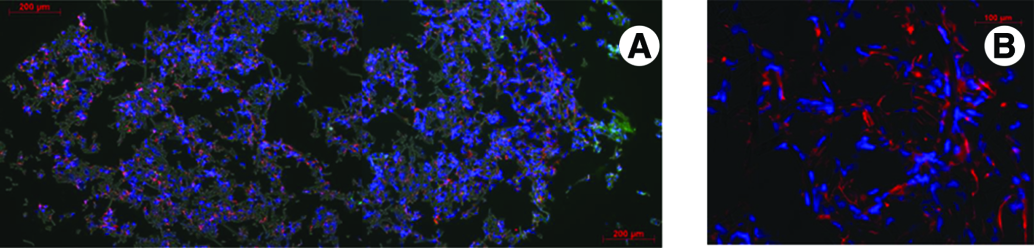
Growth of myoblasts and hESCs on nanofibrous scaffolds
Both the myoblasts and the stem cells did not manage to infiltrate deeply into the electrospun nanofibrous scaffolds. A few individual cells managed to grow as deep as 500 μm into the scaffold, but the vast majority of the cells were not able to go past 200 μm deep (see Fig. 3A, D). However, in the hydrospun layered nanofibrous scaffold, a vastly improved penetration was observed, reaching a depth of 1000 μm at some points. The myoblasts cells inside the scaffold appear large and healthy, with rounded nuclei and elongated morphology, as observed by staining for desmin. Both the myoblast and the stem cells were able to reach the large spaces between the layers of the scaffold, and proliferate in them (see Fig. 3B, C, E, F).

(
Growth of myoblasts in the hydroseeded microfibrous scaffold
During the layered hydrospinning, we have manually seeded myoblasts on each layer, in specific locations, before covering it with the next layer. The resultant scaffold was incubated in medium for 4 days before being sectioned and stained. The myoblasts have proliferated inside the scaffold, and have remained viable. An equal density of cells is noticeable throughout the scaffold (see Fig. 4). The results support the hypothesis that cell seeding can be done with ease during layered hydrospinning, in order to create an initial equal density of cells throughout the 3D scaffold. This method could also allow in the future a patterned seeding, to obtain a defined 3D organization of cells in the scaffold.
(
Discussion
It is clear that the structural properties of the hydrospun scaffolds are very much different from traditionally electrospun scaffolds. As demonstrated in the SEM images (see Fig. 5) and derived from the layered hydrospinning process, the hydrospun scaffolds are composed of distinctly separate layers. Those layers interact with each other, and between the wrinkles of each two layers, large empty spaces are created.

SEM images depicting cross sections of the hydrospun layered scaffold (
The reason for the large difference in thickness between the layered hydrospun scaffolds and the electrospun scaffolds probably lies in the ability of the layers to separate from each other. When the hydrospun scaffold is created, the spaces between the layers are soaked with water. When placed in a vacuum environment immediately after the hydrospinning process, the entrapped water evacuates the scaffold through the layers, stretching and extending them in the process. This explanation could also clarify why the microfibrous layered hydrospun scaffold is not as thick as its nanofibrous compatriot (see Table 1). The layers composed of microfibers are much more permeable to water, and so they do not experience the same kind of force the water exerts on the nanofibrous layers to pass through. Even when the scaffold is removed from the vacuum environment, the extremely porous structure retains its shape. Due to the stretching of the layers, the gaps between the nanofibers are also widened, resulting in larger pores, apparently due to the high ductility in room temperature of the PCL nanofibers. 23 Evidence of the increased porosity can be seen in Figure 6, where the scaffolds were cut open with a sharp blade, and the layered build was revealed (see Fig. 6B). Since the overall thickness of the microfibrous scaffold was 0.75 cm and it is known that 100 layers were picked up, the space between each pair of layers should be approximately 75 μm. The gaps that remain between the stretched layers are actually extremely large pores that add to the overall porosity of the scaffold and enable cellular growth.
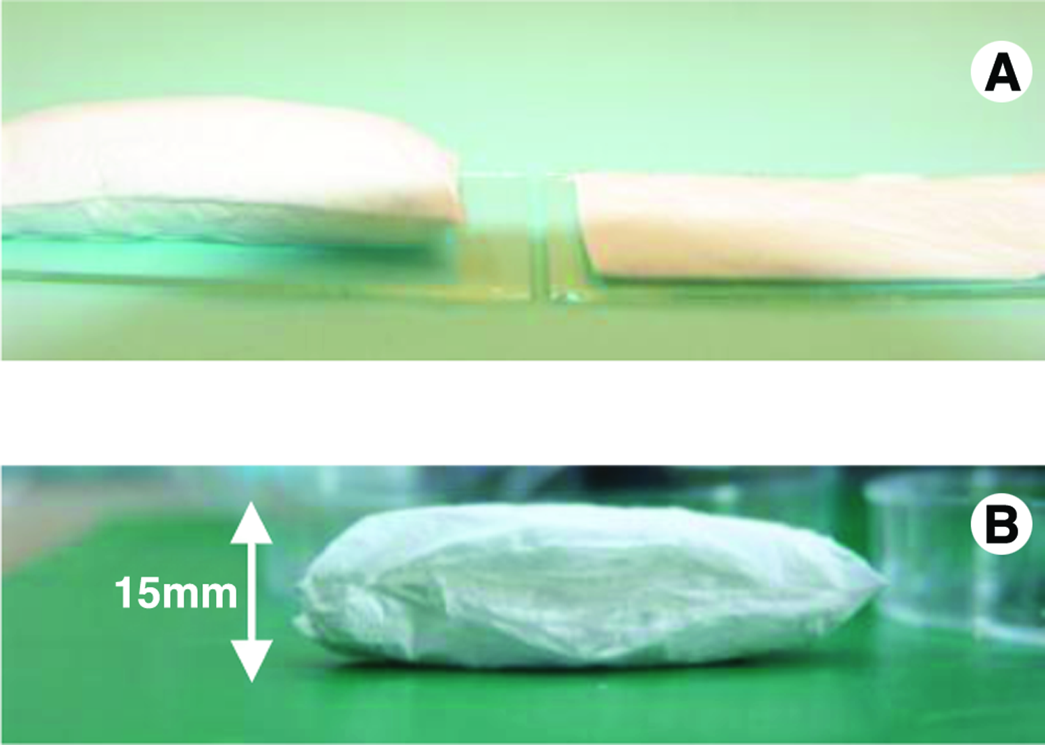
(
The difference in the ordinary pores size between the hydrospun and the electrospun scaffolds (see Table 1) can also be explained by the fact that the fibers are still electrically charged when they fall onto the conductive collector. Since in the traditional electrospinning the collector is solid, the fibers gather one on top of the other and retain sufficient residual charges to repel each other.24,25 Nanofibers that form the boundaries of a pore will likely repel the next charged fiber approximately to the center of the pore, where the electrostatic repulsion force is minimized. Schematically, this will create two pores half the size of the original one. However, in the hydrospinning, if the fibers drop onto the liquid media, they discharge immediately, and the next falling fiber will not be repelled to the center of the pore. Indeed, the created pores of the fabricated hydrospun scaffold are thus larger than the comparable electrospun scaffold (see Table 1).
Layered hydrospinning has three main advantages over traditional electrospinning. First and foremost, it is a method that allows the creation of extremely thick and porous scaffolds in a realistic time period that can be used for tissue engineering. Second, the created scaffolds have larger pores and a much higher porosity than comparable electrospun scaffolds. Last but not least, cells can be seeded during the hydrospinning process, providing a new method of tissue printing.
In this work we have shown that both myoblasts and hESCs were able to infiltrate into the hydrospun layered scaffolds and proliferate in the large spaces between the layers. When compared with the poor growth on the comparable electrospun scaffolds, the difference is striking.
Based on the above evidence, the layered hydrospinning demonstrates a novel method highly suitable for the construction of a 3D scaffold for tissue engineering, with patterned seeding and 3D organization of cells in the scaffold.
Footnotes
Conflict of Interest
No competing financial interests exist for the authors R.T., E.Z., and S.L.
Acknowledgments
This study was partially supported by Israel Science Foundation (ISF) and Russel Berrie Nanotechnology Institute (RBNI).