
Abstract
For adequate histological processing of implanted biomaterials or tissue-engineered constructs, it is sometimes essential to obtain insight into the localization of structures inside the tissue samples. Observation of three-dimensional (3D) surface reconstruction, including basic photorealistic texture characteristics as surface pattern and color combined with X-ray computed tomography 3D reconstruction at different levels, is a useful approach to localize anatomical or implanted structures within experimental tissue samples. Because of the possible observation of structures of interest in a 3D environment, fusion of these techniques can greatly facilitate histological processing.
Introduction
Further, basic information of the object, such as surface pattern and color, is lost when processing the sample. Recording and the availability of this information can be very useful when evaluating and analyzing results. The application of 3D surface reconstruction (SR) can be a useful tool to localize structures of interest within an object because of the additional photorealistic texture information like color and surface pattern.1,2 In addition, computed tomography (CT) techniques such as X-ray cone beam CT and micro-CT can be used to view radio-dense biomaterials (metals and ceramics) within the specimens. A combination of 3D SR models and 3D CT models can then give more insight into the exact localization of the scaffold, and thus how to handle the sample for further histological processing.3,4,5
Therefore, for the current study we hypothesized that fusion of a transparent 3D SR model including all surface information and landmarks, with the 3D model derived from CT is an optimal approach to facilitate the exact localization of anatomical structures, biomaterials, and tissue-engineered scaffolds, and further tissue processing.
Materials and Methods
Used specimens
A small sphere with a 1.5 cm diameter was used to determine the calibration error of the 3D SR setup, by checking whether the object became indeed reconstructed as a sphere. A hydroxy-apatite-phantom cylinder of 4 mm in diameter and 6 mm in height, normally used in bone mineral density research, and an air-dried extracted human molar with evident caries were used for 3D SR to check the minimal size of objects as can be studied and combined in 3D SR and 3D micro-CT models.
The right part of the lower jaw of a macaque monkey, with dimensions of approximately 7.5 cm in length and 2.5 cm height and containing a modular endoprosthesis made of Ti-Al6-V4, was used to make a 3D SR, as an example of a structure of larger dimensions. Finally, the left part of a porcine lower jaw, with dimensions of approximately 25 cm in length and 15 cm in height, was used. In this jaw, three radio-dense reference objects—a titanium disk (diameter, 6.0 mm; height, 0.8 mm), a massive titanium rod (diameter, 4.0 mm; length, 3.0 mm), and a titanium screw implant—were placed at different positions to analyze whether landmarks can be added for proper localization of the object of interest. Therefore, first an incision was made in the connective and muscle tissue surrounding the jaw bone, followed by the installation of the titanium rod and titanium screw implant into the two holes as drilled in the jaw bone. The titanium disk was placed subcutaneously. Finally, the connective tissue and muscle tissue were sutured back in place. All samples were fixed for 10 days in a 4% formaldehyde solution, rinsed using demineralized water, and placed into a 70% alcohol solution.
3D SR
For the examination of all three types of specimens, a 3D SR setup was established (Fig. 1). The sample was placed on a mold made of Optosil Comfort Putty combined with Optosil Xantopren universal activator paste (Heraeus Kulzer, Dormagen, Germany) and placed on a rotating horizontal stage containing a calibration sheet for registration of the landmarks.

Three-dimensional surface reconstruction (3D SR) setup. Regular illuminated sample on rotation step table, acquiring images on an angle of 45°. Color images available online at
Images were taken using a Nikon (Nikon, Tokyo, Japan) D70 camera and a Nikon Nikkor AF-S 18–70 mm or Sigma (Nieuwegein, The Netherlands) 105 mm 1:2.8D DG Macro objective, depending on the size of the sample, under a fixed angle of 45°, each 10° of the total rotation of 360°, resulting in 36 high-resolution images (3008 × 2000 pixels). The specific software iModeller 3D Professional Edition 2.6 (UZR & Co, Hamburg, Germany) was used for 3D SR.
X-ray CT
Depending on the size of the sample studied, two different methods of X-ray CT were used. Micro-CT under optimal conditions theoretically can have a maximal special resolution of 4–5 μm, whereas whole-body CT systems can reach up to 0.2 mm. However, micro-CT is not able to handle specimen sizes above approximately 2.5 cm in diameter. In this study, we used the Skyscan 1072 desktop X-ray micro-CT system (Skyscan, Kontich, Belgium) for small objects, and subsequently the i-CAT cone beam 3D dental imaging system (Imaging Sciences International, Hatfield, PA) for large objects.6,7
The Skyscan 1072 desktop X-ray micro-CT system has a focal spot of 7 μm, a 1024 × 1024 × 12 bit digital-cooled CCD X-ray detector, and the scanning settings were set to magnification 15 ×, rotation step 0.9°, field of view 19.13 mm, and X-ray source 100 kVp, 98 μA (10 W). The distance from the sample to the detector determines the magnification factor. The cone beam reconstruction method according to Feldkamp was performed using the NRecon v1.4.4 (Skyscan) software package.
The X-ray source of the i-CAT system, with a high-frequency fixed anode, was set to 121 kVp and 47.74 mA. Compared to micro-CT, resolution was notably lower with a focal spot of 0.5 mm. In contrast to micro-CT, where the X-ray beam and detector are fixed and the sample is rotating, in the i-CAT machine the X-ray beam and detector are rotating 360° around the sample during image acquisition, with a rotation step of 1.15°. Further, iCAT did not involve magnification of the image beyond 1 ×. During rotation, the amorphous silicon flat panel image detector of 20 × 25 cm in dimension, containing a cesium iodide conversion layer, acquired all projected images in 12-bit gray scale. Thereafter, using the i-CAT image reconstruction algorithm, the projected images were reconstructed and converted into a stack of DICOM format image files and converted from 16-bit gray scale to 8-bit gray scale images using 3D-Doctor software. In principle, the iCAT system can also scan for soft tissue contour, but only with very limited resolution and no information on texture and color.6,7 Hence, this acquisition mode was not applied.
For both techniques, subsequently, the files were imported in CT-Analyser V1.7 (Skyscan) and then re-sliced, and the volume of interest was selected, while images without useful information were discarded. The volume of interest files was imported in 3D-Doctor (version 4.0) (Able Software, Lexington, MA) and interactive segmentation was performed to generate bone object boundaries (gray value range, 190–255). A 3D polygonal representation was finally generated using complex surface rendering with the recommended software settings for denseness of triangle mesh using Rhinoceros (version 4.0). Flamingo (version 1.1) software (Robert McNeel & Associates, Seattle, WA) was used for 3D reconstruction and full-color photorealistic rendering of 3D SR models.
Results and Discussion
The 3D SR setup proved easy to construct; using SR software, representative suitable and reliable 3D SR models could be created. Creating and merging 3D models derived from different techniques requires standardization. A relative solid ingenious 3D SR technique was chosen to create 3D SR models using commercially available semiautomated software. A correct 3D SR setup, decent calibration, and a uniform white background were essential for acquiring suitable images for 3D SR software processing. Out of focus and shadow of the object influence the image quality and therefore the final 3D SR model. Further, attention must be paid to the angle between the camera and horizontal surface on which the sample is placed to avoid distorted 3D SR models. When increasing the angle, texture information located at the base of the sample was reduced, while decreasing the angle, the surface texture information at the top of the sample was reduced. Although the creation of a second 3D SR model of the same object after turning it upside down and the junction of this model with the first initial 3D SR model can presumably optimize the final merged 3D SR model, this was not necessary for the purpose of our study. Besides a higher pixel size of the images, the resolution and texture of the 3D SR models can be increased when acquiring more images at smaller standardized rotation angles. The mesh resolution also plays an important factor in the final 3D SR model. Increasing the mesh resolution will improve the number of polygons color and texture detail, but will also amplify noise and errors from the original two-dimensional images.
Using CT systems, the micro-CT and i-CAT equipment, 3D models of objects of different sizes can be generated. Further, by utilizing specific software programs, merging of 3D SR and 3D CT models was found to be possible.
Results 3D SR
By performing SR software processing, the reference points on the calibration sheet were used to align all images, and a masking tool was used to select the parts that were to be reconstructed (Fig. 2). Finally, a wire-frame or plain 3D model was created using surface rendering. The model could be created and viewed using a different mesh resolution depending on the final resolution of the 3D model. The texture mode finally created the color and pattern of the objects' surface, whereby all texture information was saved in a separate texture chart file. Increasing the mesh resolution and the number of polygons resulted in more detailed smooth 3D SR models with less jagged objects. However, amplified errors and artefacts were induced when the mesh resolution was set to the maximum (4.41 × 10⁴ polygons). The texture file charts showed clearly the increasing amount of polygons and related texture information of each different mesh resolution setting (Fig. 3).

Three-dimensional SR software processing: a sample placed on calibration sheet containing reference points to align all images. Color images available online at

Three-dimensional SR software processing of a human molar: mesh resolution (polygon number) related to 3D SR texture quality. Increase in polygon number is related to increase in smoothness and texture. Red arrows indicate jagged 3D objects due to low number of polygons (102). Blue arrows indicate artefacts at maximum mesh resolution (4.41 × 10⁴ polygons). Color images available online at
Using a standardized model as a sphere, the 3D SR setup could be checked, calibrated, and eventually corrected. Three-dimensional SR was possible of objects of different sizes, from a few centimeters as the human molar, up to approximately 20 cm as the porcine mandible. Three-dimensional SR showed clearly the texture information as surface pattern and color of these samples as depicted in Figure 4.
Final 3D SR models of (
Different software packages could be used to merge the two separated 3D models derived from the different SR and CT techniques. The most suitable compatible 3D format files when merging 3D SR and 3D CT reconstruction using the Rhinoceros software package including texture characteristics are object (OBJ) and three-dimensional studio (3DS). The stereo lithography (STL) format file without texture information is sufficient for creating 3D CT models.
The 3D SR of small objects was complicated due to the increased influence of the SR setup, like focusing, camera angle, and distance of the sample from the camera.
Results 3D CT
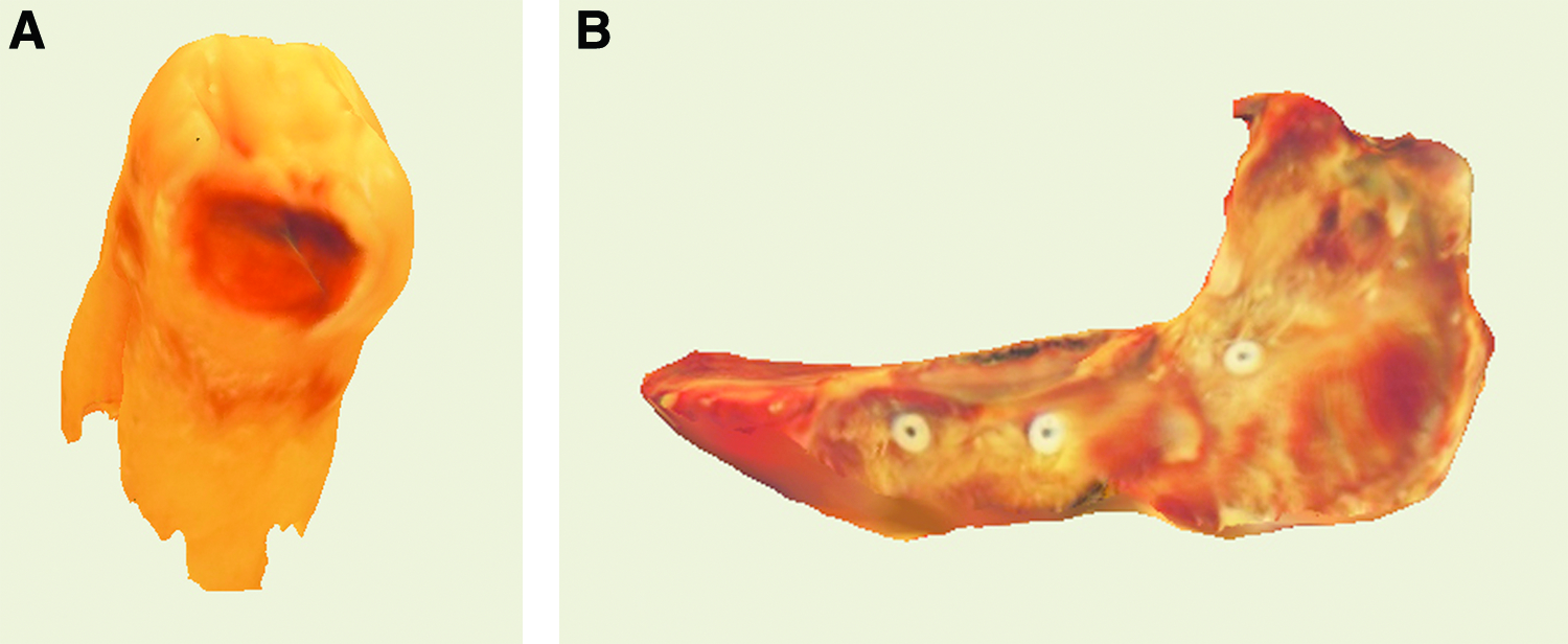
The major advantage of the micro-CT system for small objects is the relative high resolution, due to the small focal spot size and distance of the sample to the detector compared to the i-CAT cone beam CT system. Therefore, the dimensions of the objects to study determine the choice of X-ray CT. Using the micro-CT system, the affected human molar showed a diversity of different radio densities through which several internal structures of the human molar as root channels, dentine, and enamel could be viewed in 3D (Fig. 5).
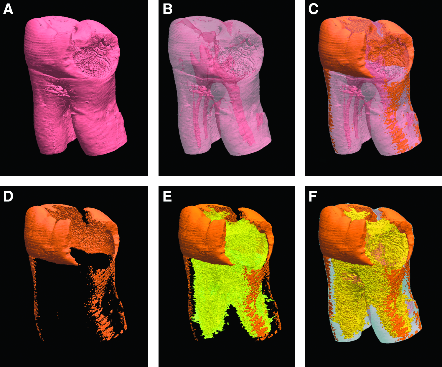
Observation of 3D micro-computed tomography (CT) models of a caries affected human molar (in pink,
Performing X-ray CT, the i-CAT cone beam X-ray CT system was used, which has a higher resolution compared to traditional conventional whole-body CT systems, while the cone beam reconstruction is not limited by distortion, magnification changes, restricted clarity, and lack of accuracy in image measurements. The i-CAT provides high-definition images at 0.2 mm voxel size of objects up to 17 cm in diameter and 13 cm in height. Additionally, implanted biomaterials are easy to locate in large samples. A disadvantage remains the low resolution compared to micro-CT. Nevertheless, the i-CAT cone beam CT application, in combination with the i-CAT-specific observation software showed clearly the radio-dense massive and hollow titanium landmarks as placed in the porcine mandible (Fig. 6). These landmarks were not only visible in two-dimensional cross sections, but could also easily found back in the final generated 3D reconstruction. The location of the massive titanium implant in the lower jaw of the macaque was also detectable.
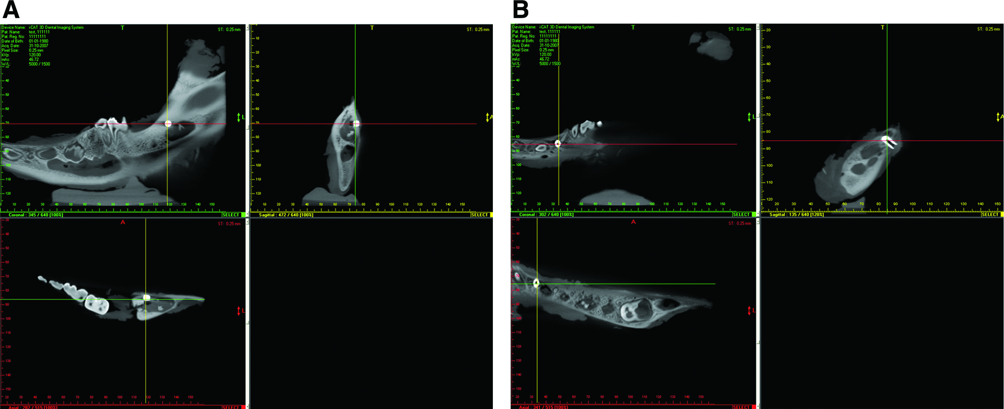
Coronal, sagittal, and axial views of the locations of an implanted titanium disc (
Fusion of 3D SR and 3D CT models
Merging the 3D SR and the 3D micro-CT of the human molar associated the surface information with the internal structures of the molar. The distance of the affected dark reddish brown transparent SR model to the radio-dense structures viewed by micro-CT was simple to determine (Fig. 7A). For this purpose, the 3D SR and 3D micro-CT models were imported into 3D-Doctor software, followed by Rhinoceros software (version 4.0; Robert McNeel & Associates), for scaling, rotation, and full-color photorealistic rendering. This resulted in both 3D models placed on each other. Merging and full-color photorealistic rendering, including lights, transparency, shadows, and textures, of the 3D SR models was done using Flamingo (version 1.1) (Robert McNeel & Associates) to enhance observation of the evident caries and finally to determine the dimensions and depth of the caries.
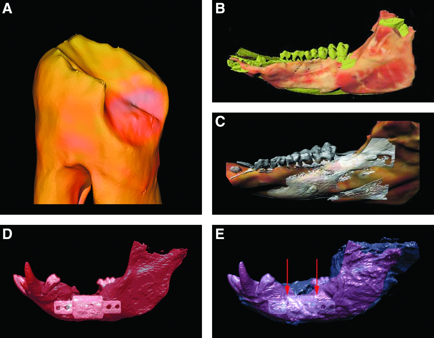
Observation of merged 3D SR and 3D CT models and localization of implanted biomaterials in tissue. (
When the porcine jaw was evaluated, a similar result was obtained, but one additional step was required, that is, using the 3D-Doctor software program, both 3D SR and 3D CT models were imported and the shape function had to be used to adjust the X, Y, and Z rotation values in degrees, and X, Y, and Z moving values of the 3D models were adjusted within the 3D space. The X, Y, and Z scaling values were kept constant. Re-positioning was also performed using the Rhinoceros software transforming functions as moving, 3D scaling, 3D rotating, and alignment.
Finally, the surface of the imported 3D SR model was rendered using Flamingo software, and the texture transparency intensity was set to 75%. When the transparent color 3D SR model and the 3D CT model were merged, the underlying 3D CT model became clearly visible (Fig. 7B, C) showing texture and color, and the implanted biomaterials within the object of interest. Radiopaque landmarks as titanium rods placed into the tissue or in combination with colored features as small ink spots placed onto the objects surface display in combination with the localization of structures within the 3D CT model how to handle the object for further histological processing as sawing and slicing. Additional evidence of the usefulness of merging 3D SR and 3D cone beam CT was provided during analysis of the macaque tissue sample.
Besides adding an extra box and the X, Y, and Z axes, the position of the structure of interest was easily located. The exact localization of the object assisted and facilitated how to cut and handle the tissue for further histological processing. Using different gray value threshold settings in 3D-Doctor™ software, variations in transparency of the different 3D CT models as the radiopaque titanium implant in the more radio-dense lower jaw tissue of the macaque contributed in better observation of implant both in hard and soft tissue (Fig. 7D, E). The exact location of the implant depicted in Figure 7, as well as the informative texture features of the transparent soft and hard tissues, assisted in a proper histological sectioning of the sample, that is, perpendicular to the red arrows.
Registration of the two different 3D models, 3D CT and 3D SR, is an important essential step for fusion of the models.3,4,5,8,9,10,11 Besides ink or other marks placed onto the object surface, X, Y, and Z axes placed into the 3D space can be used as additional tool for localization of the implanted biomaterials. Even though automatic registration in 3D is often used, scaling and landmark–based registration of both complete 3D models, 3D CT and 3D SR, into a 3D space can be done manually with the use of ink placed on the objects surface or metal rods placed in the tissue. Further, automatic registration of complete 3D models, as iterative closest point algorithm used to merge two cloud-point models, is not always incorporated in all 3D reconstruction software programs.
Conclusion
Observation of 3D SR, including basic photorealistic texture characteristics as surface pattern and color combined with X-ray 3D CT reconstruction at different levels, is a useful approach to localize certain anatomical structures, biomaterials, or tissue-engineered scaffolds within experimental tissue samples. Because of the possible observation of structures of interest in a 3D environment, fusion of these techniques can greatly facilitate histological processing. As described herein, the technique is rather elaborate and thus only feasible for delicate specimens that require exact processing. However, after establishment of the technique, the development of hardware and software applications will be optimized to simplify the combination of 3D observation and inspection techniques in the future.
Footnotes
Disclosure Statement
No competing financial interests exist.