
Abstract
Poly(ethylene glycol) (PEG) hydrogels have been investigated for a number of applications in tissue engineering. The hydrogels can be designed to mimic tissues that have desired chemical and mechanical properties, but their physical structure can hinder cell migration, tissue invasion, and molecular transport. Synthesis of porous PEG hydrogels could improve transport, enhance cell behavior, and increase the surface area available for cell adhesion. Salt leaching methods have been used extensively to generate porous biomaterial scaffolds but have not previously been applied to hydrogels. In this article we describe a modification of traditional salt leaching techniques for application to hydrogels. Salt-saturated polymer precursor solutions are prepared, and salt crystals of a defined size are added before polymerization. The salt crystals are then leached out, resulting in porous hydrogels. Examples are provided for application of this technique to PEG hydrogels. Porous PEG hydrogels were generated with pore sizes ranging from 15 to 86 μm and porosities from 30% to 75%. Porous hydrogels that were incorporated with a cell adhesion peptide supported cell adhesion with morphology varying with pore size. The simple, reproducible technique described here could be used to generate porous hydrogels with controlled pore sizes for applications in tissue engineering.
Introduction
Porous scaffolds have been applied extensively in tissue engineering.16,18–20 Introduction of pores creates more space for cell migration and tissue invasion, increases surface area–to–volume ratios for cell seeding, and facilitates nutrient transport.
21
Pores have been shown to enhance scaffold vascularization
22
and wound healing.
23
A number of approaches have been used to generate porous scaffolds. The most common is solvent casting followed by particulate leaching. A typical application uses salt particles of a defined size range as porogens. Polymers are assembled in the presence of the insoluble salt crystals, which are subsequently leached out by incubation in large volumes of water. This technique is routinely applied to polymers soluble in organic solvents, including poly(
Gas-forming techniques have been used to generate PEG hydrogels with pore sizes ranging from 100 to 600 μm. With this technique it is difficult to control pore size and ensure pore interconnectivity.25,26 Polymer–polymer immiscibility can be exploited to generate porous hydrogels when only one phase is polymerizable. The other, nonpolymerizable phase acts as a porogen that can be extracted from the resulting material. Porous dextran hydrogels have been created with broad size distribution from 10 to 120 μm by varying concentrations of methacrylated dextran with PEG. 27 Macroporous poly(N-isopropylacrylamide) (PNIPAAM) hydrogels have also been synthesized by using PEG as the pore-forming agent.28,29 In addition, macroporous PNIPAAM hydrogels have also been created by polymerizing PNIPAAM in different concentrations of aqueous solutions of NaCl to induce phase separation. 30 Although porous hydrogels can be generated with these methods, the overall structure of the gel was not consistent with structure varying from fibrous to a foam-like depending on the conditions used. It is difficult to precisely control the pore size with these methods. 25
Salt leaching methods offer a number of advantages in generating porous materials for tissue engineering application. The methods are simple and reproducible, and allow a wide range of pore sizes to be generated. The focus of this research was to develop and evaluate a salt leaching technique for generation of porous PEG hydrogels. To our knowledge, salt leaching methods have not been previously applied to PEG hydrogels, likely due to the use of aqueous solvents. Examples are provided to show that this method can be used to generate PEG hydrogels with interconnected pores. For the conditions described here, mean pore size ranged from 15 ± 6 μm to 82 ± 6 μm and porosity from 30% to 74%. The porous hydrogels supported cell adhesion when incorporated with ECM adhesion peptides. These materials can be used to examine the influence of pore size and porosity on cell behavior and function of engineered tissues.
Materials and Methods
Materials
PEG (Mn ≈ 8000), hexane (reagent grade, ≥95%), acryloyl chloride (98%), triethylamine (99.5%), toluene (anhydrous, 99.8%), NaCl, and 2-hydroxy-2-methylpropiophenone (Irgacure 1173) were obtained from Sigma (St. Louis, MO). Sodium chloride (≥99.5%) was from Fisher Scientific (Pittsburgh, PA). fluorescein isothiocyanate (FITC)-conjugated bovine serum albumin (FITC-BSA) was purchased from Invitrogen (Pittsburgh, PA).
Synthesis of PEG diacrylate
PEG-diacrylate (PEG-DA) was prepared using a previously published method. 31 The structure and purity of the products were verified by Fourier transform infrared spectroscopy (FTIR) (Tensor 27 FTIR; Bruker, Billerica, MA) and 1H NMR (Advance 300 Hz; Bruker). To perform 1H NMR, the product was dissolved in CDCl3 with 0.05% v/v of tetramethylsilane as an internal standard. The acrylation efficiency of PEG-DA obtained was 95 ± 3% based on 1H NMR.
Salt leaching method
The application of salt leaching techniques to the synthesis of PEG hydrogels was performed by preparing the hydrogel precursor as a saturated salt solution (Fig. 1). The saturated hydrogel precursor was prepared by dissolving 250 mg of PEG-DA (average Mn ≈8000) in 1 mL of saturated salt water. Irgacure 1173 (0.5% w/v) was then added to the precursor as the photoinitiator. When PEG was added to the solution, some salt precipitated as crystals. The solution was centrifuged at 0.5 relative centrifuge force for 0.5 min to pack the precipitated salt (Fig. 1). The transparent top layer containing dissolved PEG-DA was collected to be used as the hydrogel precursor. The precipitated salts were saved for the generation of porous PEG hydrogels with small (<20 μm) pore size (Fig. 2).
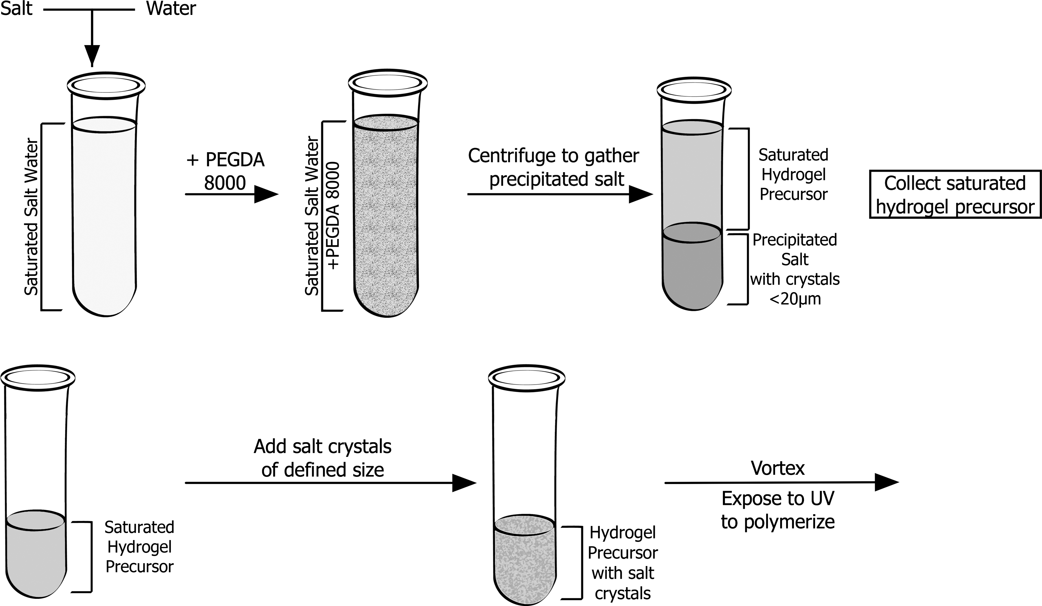
Schematic representation of the technique for generating porous hydrogels. Salt crystals precipitate after poly(ethylene glycol)–diacrylate (PEG-DA) is added to a saturated salt solution. These crystals are removed by centrifugation and the supernatant is used as the polymer precursor. Salt crystals of a defined size range are added to the precursor, which is then polymerized upon exposure to UV light. The precipitated salts can be used as the porogen to generate hydrogels with pores <20 μm.
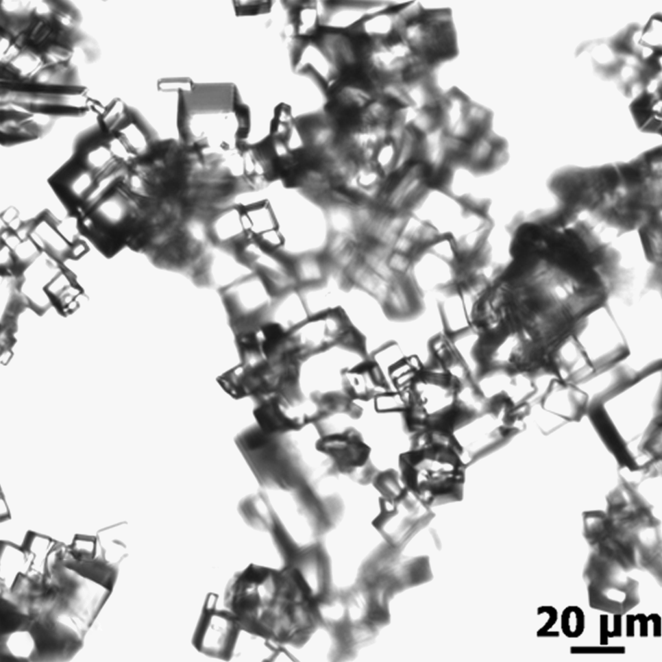
Phase contrast image of salt crystals precipitated after addition of PEG-DA to the saturated salt solution with a size range 5–20 μm.
There are three groups of salt crystal sizes used to create three different porous hydrogels; salt crystals generated by the addition of PEG to the saturated salt solution (5–20 μm) and sieved salt crystals ranging from 25 to 50 μm and 50 to 100 μm. Sieved salt crystals were prepared by grinding NaCl crystals using a mortar and pestle and then selecting crystals sizes using sieves (Precision E-forming LL, Cortland, NY). For smaller pores the crystals precipitated from the saturated salt solution were prepared as described in the paragraph above. All gels were made in 1.5 mL centrifuge tubes resulting in cone-like structures (Fig. 2). One hundred milligrams of salt particles was dissolved into 200 μL of hydrogel precursor. The salt particles and precursor were vortexed to minimize aggregation. In one condition, gels containing sieved salt crystals were immediately polymerized after addition of the salt crystals (“static”), whereas in the other condition gels were centrifuged to pack the salt crystals before polymerization (“centrifuged”). Both solutions were polymerized under UV light (365 nm) for 5 min. The salts were leached out of the gel by incubation in deionized water (DI) water changed every 2 h for 8 h. The gels were then incubated in DI water overnight. The nonporous gels were prepared by polymerizing the saturated precursor solution without the addition of salt crystals.
Confocal imaging of pore structure
Porous structure within the gel was determined by exploiting the selective partitioning of proteins into the pores of the hydrogels and not the hydrogel network. In one case a center portion of the hydrogel was dissected out to image pore structure in the bulk of the material. To further verify pore interconnectivity, entire hydrogels were incubated with a 0.5% (w/v) solution of FITC-BSA (rs = 3.5 nm) 32 overnight. After reaching equilibrium, a center portion of the hydrogel was dissected out and imaged to determine whether FITC-BSA could diffuse into the center of the hydrogel. FITC-BSA is too large to diffuse into the polymer network structure but can easily fit diffuse within the pores. 33 Confocal microscopy was performed to examine the distribution of the fluorescent molecules, which was representative of the pore structure.
A PASCAL laser scanning microscopy system from Carl Zeiss MicroImaging, Inc. (Thornwood, NY), was used for confocal imaging. The hydrogel was imaged using a 488 nm laser and a 505 nm low pass filter. Images had x and y resolution of 3.5 μm/pixel and z resolution of 20 μm/pixel. The serial images were exported into Axiovision 4.5 (Carl Zeiss, Göttingen, Germany) for reconstruction. For porosity measurements, a custom automatic measurement program in Axiovision (v4.6; Carl Zeiss, Göttingen, Germany) was used to measure total void volume within the hydrogels. The program used thresholding to determine the area of fluorescent space (pores) and compared it to the total area of the image. For each sample, pore diameters were measured manually using Axiovision along the longest axis.
Swelling
The swelling ratio of porous and nonporous gels were determined using standard methods. Gels were swelled in DI water overnight and then removed from the solution. Residual water was removed using a Kim wipe and the swelled weight determined. Samples were then placed into a vacuum dryer (Fisher Scientific, Morris Plains, NJ) at 40°C for 3 days and weighed for the dry weight. The swelling ratio was obtained by dividing the swelled weight by the dry weight.
RGD conjugation
A cell adhesion peptide (arginine–glycine–aspartic acid, RGD) was covalently attached to PEG as described by Elbert et al. 34 A solution of 50 mM NaHCO3 (pH 8.3) was prepared as a buffer. Ten milligrams of YRGDS (American Peptide, Sunnyvale, CA) was dissolved in 5 mL of 50 mM NaHCO3. Acryl-PEG-SVA (3400 Da; Laysan, Arab, AL) was dissolved in 7 mL of 50 mM NaHCO3 and then added drop-wise into the stirred YRGDS solution in the dark. The molar ratio of YRGDS to acryl-PEG-SVA was 1:1.5. The solution was stirred for 2 h. The final product was dialyzed (2000 Da molecular weight cut-off) in 2L of DI water for 24 h (water replaced after 12 h). The dialysis products were lyophilized and stored at −80°C until use.
RGD porous gel preparation and cell seeding
To prepare porous PEG hydrogels containing RGD, 10 mg of conjugated Acr-PEG-YRGDS was suspended in 1 mL of the saturated salt solution containing 25% (w/v) PEG precursor. Salt crystals were added, gels were crosslinked, and porogen was leached out as described in the previous section. The porous gels were cut into 3-mm-thick disks and washed three times with cell media. The cell culture method has been described previously. 35 NIH 3T3 fibroblasts (Cambrex, Walkersvile, MD) were maintained in complete media (Dulbecco's modified Eagle's medium, 10% fetal bovine serum, and 1% penicillin–streptomycin). Gels were placed into 48-well plates, and 0.5 ml of 10,000cells/mL was added directly to the cell surface. Samples were incubated at 37°C, 5% CO2 overnight before imaging.
Staining
Cells cultured on the gels were imaged by staining for the cytoskeletal protein phalloidin. Alexa Fluor Phalloidin (Invitrogen, Eugene, OR) was reconstituted in 1.5 mL of methanol to yield a final concentration of 200 units/mL. Twenty-five microliters of this solution was diluted into 1 mL of phosphate-buffered saline (PBS). The diluted phalloidin solution was stored at −4°C. Cell-seeded porous gels were rinsed twice with PBS and fixed with 4% paraformaldehyde for 30 min at room temperature. The sample was rinsed with PBS and treated with 5% Triton X-100 for 30 min at room temperature. The sample was rinsed and then blocked with 2% BSA for 30 min at 37°C. The sample was immersed in the phalloidin solution for an hour (37°C). The sample was imaged by confocal microscopy with the same method used to image FITC-BSA-loaded gels.
Statistical analysis
Data are presented as means ± standard deviations. Significant differences between groups of data were determined by analysis of variance with Holm–Sidak post-test. In all cases, p < 0.05 was considered statistically significant.
Results
Generation of porous PEG hydrogels
PEG-DA precursor solutions containing salt crystals rapidly assembled into gels upon exposure to UV light in the presence of a photoinitiator. Macroscopically, the gels appeared similar, but more opaque, relative to nonporous gels (Fig. 3). When porous gels were dried, the porous structure could be seen visually under brightfield microscopy (Fig. 3C). To examine 3D microstructure, the gels were equilibrated with FITC-BSA, which was then imaged using confocal microscopy. Fluorescence was not observed in nonporous gels, which is expected as FITC-BSA is larger than the mesh size of the PEG network. 33 Confocal images revealed the 3D porous structure of the salt-leached hydrogels (Fig. 4). The size of the pores varied depending on the size of crystals used. Pore interconnectivity can be observed in the high-resolution images in Figure 5, where arrows indicate pore interconnections. These images were produced by first equilibrating the gels in FITC-BSA and then dissecting out a central region for imaging. The ability of the protein to access the central region of the gel provides additional proof of the overall pore interconnectivity.
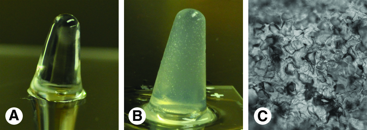
Macroscopic images of (
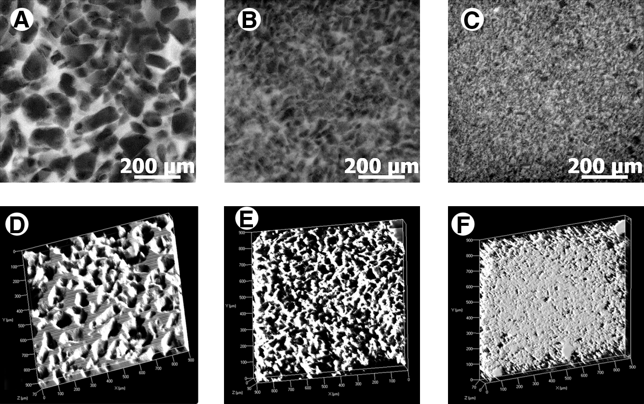
The salt leaching method is able to produce porous PEG hydrogels with interconnected pores of varying size. Confocal images of middle regions of porous PEG hydrogels generated with salt crystals in size ranges of 50–100 μm (

Sections of a confocal image of a porous hydrogel (25–50 μm) equilibrated in FITC-conjugated bovine serum albumin showing interconnectivity of the porous structure. Images (
The ability to generate porous hydrogels with pore sizes <20 μm would allow PEG to serve as a more appropriate mimic of the ECM. 36 However, it is time consuming and inefficient to generate a large mass of salt crystals of small size using grinding and sieve selection. When the precursor solution is generated, by the addition of PEG-DA to the saturated salt solution, crystals precipitate and are removed by centrifugation. To create hydrogels with small pores, these crystals were used as porogens. The precipitated crystals ranged in size from 5 to 20 μm and with mean pore size 15 ± 6 μm (Fig. 4C, F).
Porosity and pore size
Image analysis techniques were used to quantify mean pore size and porosity from the confocal images. Gels were generated under both static and centrifuged conditions. Figure 6 displays the mean pore size of gels formed with various salt crystals. There were no statistical differences between static and centrifuged gels; however, pore size increased with salt crystal size. Static gels generated with 25–50 μm and 50–100 μm salt crystals had mean pore sizes of 50 ± 1 μm and 74 ± 3 μm, respectively. Centrifuged porous gels with 25–50 μm and 50–100 μm salt crystals had mean pore sizes of 44 ± 0.1 μm and 82 ± 6 μm, respectively. Gels with the precipitate crystals had a mean pore size of 15 ± 6 μm. These data show that pore size can be varied based on salt crystal size (Fig. 6).

Mean pore sizes of porous hydrogels varied with salt crystal size. No differences were observed between gels generated under static and centrifuged conditions. Between salt crystal sizes all conditions are statistically different (p < 0.001).
Porosity was also quantified from the confocal images (Fig. 7). There were no statistical differences in porosity for static and centrifuged conditions. For salt crystals above 25 μm there were no differences in porosity. However, the porosity of gels produced using the precipitate salts (75 ± 8.7%) was significantly greater than other conditions.
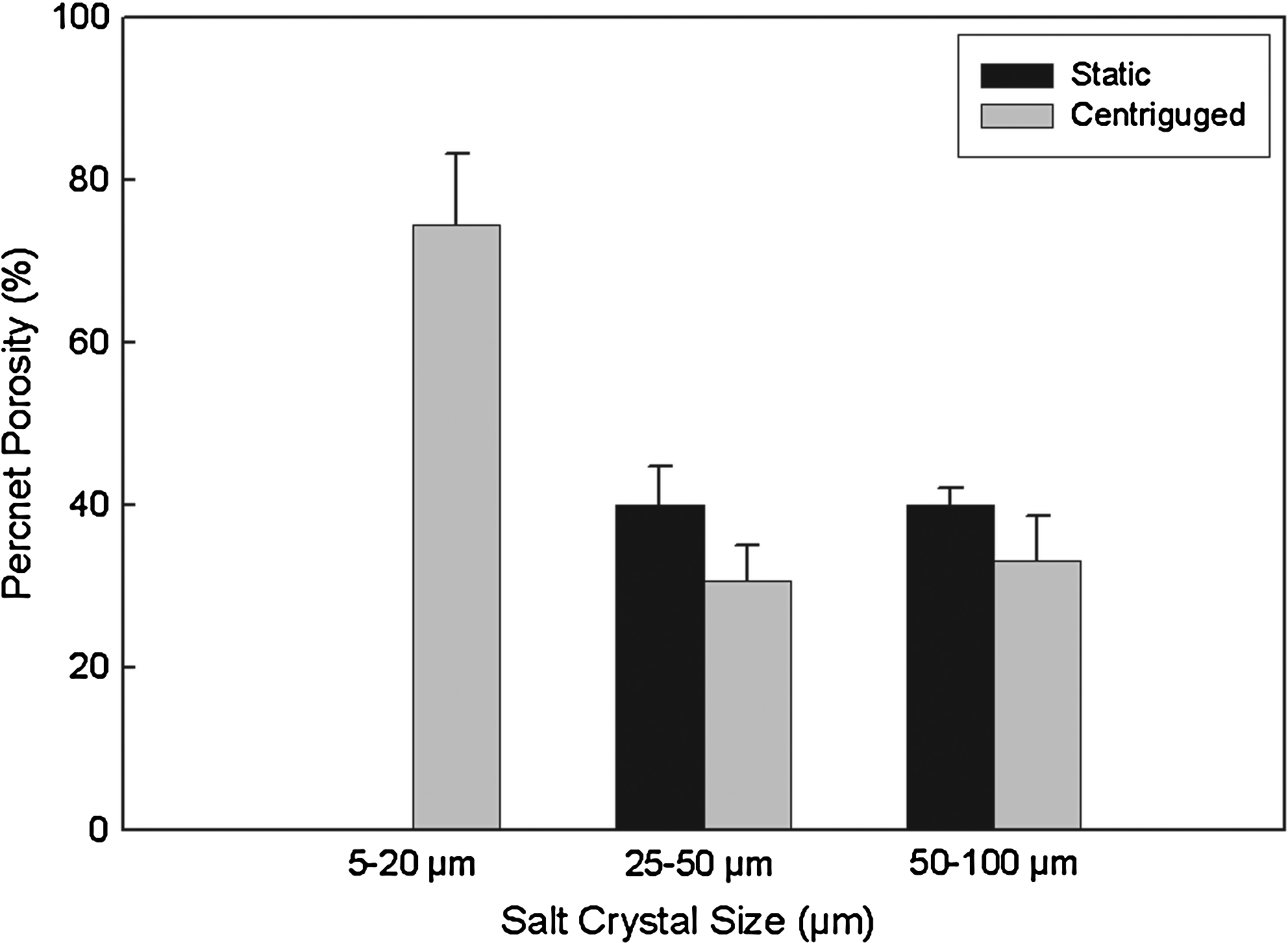
Porosity as a function of salt crystal size. All conditions are statistically different between crystal sizes (p < 0.003).
Swelling ratios
Equilibrium swelling studies were performed as an additional examination of differences between porous and nonporous gels. In all cases, porous gels had statistically higher swelling ratios than nonporous gels (Fig. 8). Porous gels formed with crystals ranging from 25 to 50 μm and 50 to 100 μm had similar swelling ratios. Interestingly, porous gels formed with precipitated salts had a higher swelling ratio than the gels formed with sieved salt crystals (p < 0.001).
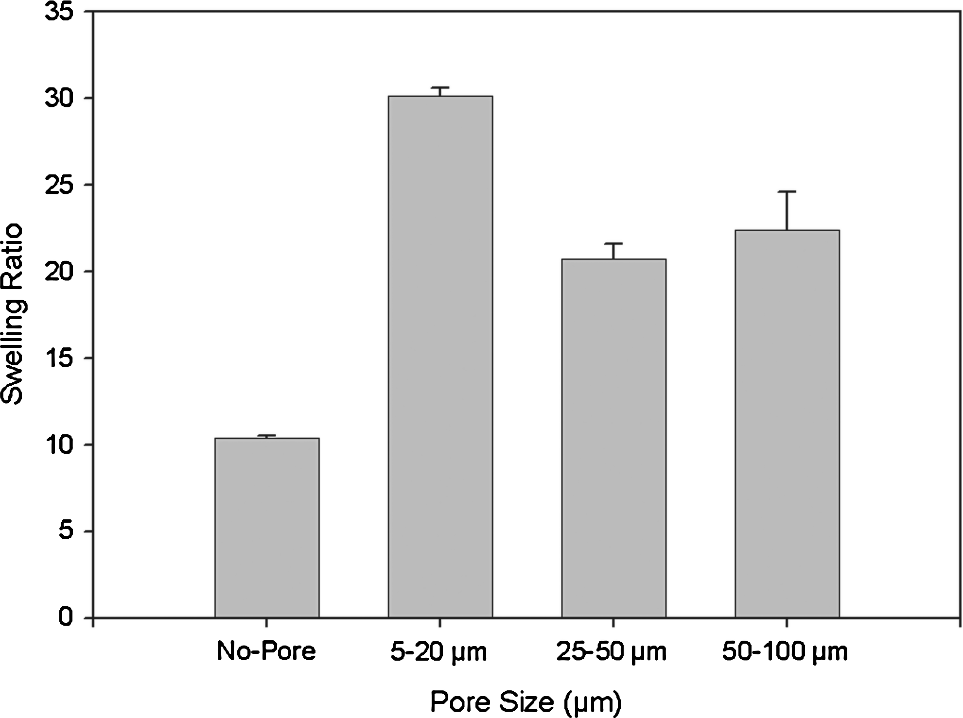
Swelling ratio of porous and no porous gels. Between salt crystal sizes, all conditions are statistically different (p < 0.001) except porous gels formed with crystals ranging from 25 to 50 μm and 50 to 100 μm.
Cell adhesion
PEG hydrogels incorporated with ECM molecules support cell adhesion.4,37 An ECM-derived cell adhesion peptide (RGD) was covalently incorporated into the porous PEG hydrogels to examine their ability to support cell adhesion. Fibroblasts were seeded onto the gels and then stained for phalloidin. Stained fibroblasts could be seen on the gels under all conditions containing RGD (Fig. 9). The cells formed extensive contacts in gels with mean pore sizes of 15 ± 6 μm (Fig. 9C) and 44 ± 0.1 μm (Fig. 9B). In gels with the largest pore size, cells formed aggregates (Fig. 9A). In nonporous gels, cells spread and formed a two-dimensional sheet (Fig. 9D).
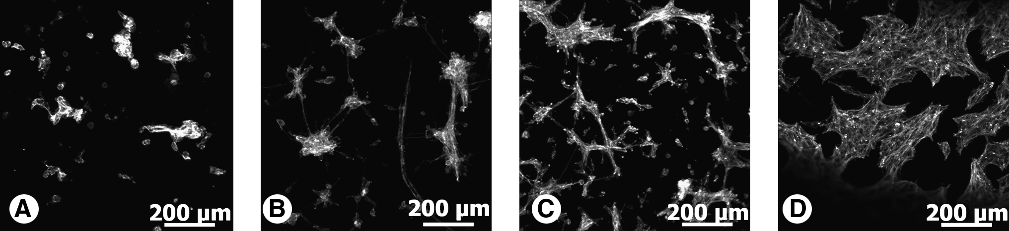
Confocal images of phalloidin-stained fibroblasts adhering to porous hydrogels with mean pore sizes of (
Discussion
Hydrogels have enjoyed extensive popularity for biomedical investigation due, in part, to the ability to control their chemical and mechanical properties. Their physical structure, however, can often alter cell behavior, slow tissue integration, and hinder molecular transport. The ability to generate porous PEG hydrogels could offer a number of advantages over nonporous gels. Salt leaching techniques have been used extensively for polymers formed in organic solvents, but, to our knowledge, have not previously been applied to PEG hydrogels. In the technique presented here, polymer precursor solutions were generated in saturated salt solutions to limit the dissolution of salt crystals added as porogens. The porogens were then leached out, leading to interconnected pores within the hydrogel.
The pore size of these materials could be controlled based on the selection of salt crystals within a defined range using sieves. The pore sizes agreed well with the crystal sizes. Historically, people have used salt leaching to generate pores within the range of 100–400 μm. These levels have been shown to be optimal for cell seeding and some tissue applications. In the hydrogels described here we focused on the generation of pores <100 μm. Studies have shown that optimal conditions for some applications require pores <100 μm, such as wound healing (optimal size 20–120 μm 23 ) and vascularization (5–15 μm 22 ). In addition, to more closely approximate natural ECM, pores should be <20 μm. 36 To create smaller pore sizes salt particles were precipitated from the saturated salt solution upon the addition of the PEG-DA macromer. These crystals were small and when used as the porogen, allowed for the generation of hydrogels with a mean pore size of 15 ± 6 μm. These hydrogels had pores smaller than what has been achieved with other methods.20,21,38–40 By generating pores of this size, the materials could be used to examine cell–substrate interactions in environments with pore sizes of the same order of magnitude as a cell. This would allow for the examination of behaviors depending on pore size such as the amoeboid-like transition of mammalian cells that occurs during cell migration in vivo. 41
After incorporation of RGD sequences into the precursor solution, the hydrogels were able to support cell adhesion and migration. Images of the cells on the gels suggest that cell behavior varies with pore size. Cells cultured on the surface of hydrogels with mean pore sizes of 15 ± 6 μm and 44 ± 0.1 μm appeared to form small aggregates with a few interconnections between the aggregates. Cells cultured on larger pores formed cell aggregates, whereas on nonporous gels spread forming two-dimensional sheets. These results suggest that pore sizes may be used to modulate cell behavior, but more extensive studies are needed to verify and understand these relationships. The technique described here could be used to further examine these material structure–cell function relationships.
We also describe a novel method for imaging porous structures within hydrogels. The most common method for imaging of porous scaffolds is scanning electron microscopy (SEM).38,42 The disadvantage of SEM in hydrogel systems is that sample preparation may alter the original porous structure. In addition, SEM does not allow observation deep within the porous scaffold. 21 In this study, the technique to analyze the hydrophilic porous scaffold was applied to a fully swelled material. By relying on the transport of FITC-BSA, this technique may not allow observation of small or inaccessible pores. However, it provides insight into the hydrogel structure under the same conditions in which cells are exposed to the material and may be used to simultaneously image migrating cells and pore structure and as a dynamic method for imaging pore structure as materials degrade.
Conclusion
A novel technique was developed for the application of salt leaching technologies to PEG hydrogels. Porous hydrogels with three different mean pore sizes were generated and pore size was dependent on the size of the salt crystals. By exploiting the selective partitioning of fluorescently labeled proteins into the material, confocal imaging could be used to image the materials under cell culture conditions without drying or processing the gels in a way that may alter their structure. This simple, reproducible technique could be used to generate porous hydrogels with controlled pore size for applications in tissue engineering.
Footnotes
Acknowledgments
This research was supported by funding from the National Science Foundation (Grant Nos. 0852048, 0731201, and 0854430) and the U.S. Department of Veterans Affairs. We thank Monica Lizet Moya, Ph.D., Megan Francis-Sedlak, Ph.D., and Bin Jiang for help with cell culture, staining, and statistical analysis.
Disclosure Statement
No competing financial interests exist.
References
Supplementary Material
Please find the following supplemental material available below.
For Open Access articles published under a Creative Commons License, all supplemental material carries the same license as the article it is associated with.
For non-Open Access articles published, all supplemental material carries a non-exclusive license, and permission requests for re-use of supplemental material or any part of supplemental material shall be sent directly to the copyright owner as specified in the copyright notice associated with the article.