
Abstract
A microfabricated electroporator (MFE) for the irreversible electroporation (IRE) of tissues has been developed by miniaturizing a clinical electroporator with a two-needle array while keeping the same electric field strength distribution. Since IRE was brought to special attention as one of the local tissue ablation techniques to treat tumors, many preclinical studies have been conducted to investigate the efficacy of IRE on animal tissues. However, some technical difficulties have been frequently encountered due to the macroscale dimension of clinical electroporators, particularly in experiments on small animal models such as the mouse or rat. Here, the MFE was proposed to solve the associated problems, resulting in time- and cost-effective experimental procedures. With the developed MFE, the effect of IRE on rat liver tissues was analyzed with time by immunohistological stainings and electrical measurement, and the experimental results were compared with those operated with the corresponding real-scale clinical electroporator.
Introduction
IRE was originally considered as an undesirable effect to prevent in reversible EP protocols, and studied only to define the upper limit of electrical parameters that could guarantee nonlethal reversible EP13,15 and as an effective method to kill microorganisms in the food industry. 16 Only during the last few years has IRE begun to receive careful attention as an important local tissue ablation technique to treat tumors. Since the first preclinical study in 2006, 16 IRE has shown to be effective for ablation of the liver,14,16,17 blood vessel,18,19 tumor, 20 heart, 21 and prostate 22 in small16,18–20 and large animal models14,17,21,22 without critical thermal damages. Other than the obvious advantages of simple and fast treatment, IRE produced a well-defined region of tissue ablation and was not affected by blood flow. It was reported that IRE spared tissue scaffold other than target cells, 15 and might be effective even in immune-depressed cancer patients. 20
Although several plate- or needle-type electrode configurations have been widely used in EP-based therapeutic studies 23 depending on the position and size of target tissues, these clinical electroporators have some technical problems in preclinical studies due to their macroscale geometry of up to several tens of millimeters. First, systemic in vivo study requires many animals to be sacrificed, especially in small animal models such as the mouse and rat, since only a limited number of EP lesions can be created within a target organ. Generally, only 1–3 EP lesions are created in the mouse or rat, whereas 2–12 lesions are created in large animal models such as the dog or pig with real-scale clinical electroporators (RCEs) depending on the relative size of tissues and clinical electroporators. Second, a high-voltage pulse generator is required for the stable operation of RCEs with a voltage output over 1 kV and current driving capability of tens of amperes when plate-pair or needle-array electrodes are used. This high performance pulse generator is not only expensive but also requires careful attention during operation to maintain safety. Third, large tissue sample sizes could lead to mishandling during the sectioning or fixation procedures.
To overcome the above-listed technical problems of RCEs in preclinical study, we have developed a microfabricated electroporator (MFE) by miniaturizing a clinical electroporator having two needles while keeping the same electric field strength distribution. The feasibility of the proposed MFE was exploited by applying IRE treatment on rat livers, and all the experimental outputs of MFE were compared with those of the corresponding RCE. Immunohistological changes were inspected within 24 h after IRE by hematoxylin and eosin (H&E) staining and terminal deoxynucleotidyl transferase dUTP nick end labeling (TUNEL) assay. Electric current measurements were conducted during the pulse application, and temperature distribution was analyzed with numerical simulation.
Materials and Methods
Design and fabrication
To design an MFE, the geometry of a clinical electroporator having two needle electrodes of 0.5 mm diameter, 10 mm length, and 5 mm center-to-center distance was scaled down 5:1 (Fig. 1A, B). The poly(dimethylsiloxane) (PDMS) wire-guide was fabricated by conventional photolithography and the PDMS replica molding process (Fig. 2A–C) 24 to fix stainless steel wires at right positions. After a patterning of 100-μm-thick SU-8 2050 film (MicroChem, Newton, MA) on a silicon substrate (Fig. 2A, B), a mixture of PDMS prepolymer and curing agent (Sylgard 184; Dow Corning, Midland, MI) was poured onto the fabricated mold and cured for 3 h at 60°C in a convection oven to complete cross-linking (Fig. 2C). After peeling off the PDMS wire-guide from the mold, SUS-304 stainless steel wires of 100 μm diameter (Nilaco, Tokyo, Japan) were tightly fitted onto the PDMS wire-guide, which had counter grooves of 100 μm width, and another flat PDMS piece was bonded irreversibly with it by plasma treatment (200 mTorr, 200 W) for 30 s using an expanded plasma cleaner (Harrick Plasma, Ithaca, NY) (Fig. 2D). Figure 2E is the photograph of the MFE.
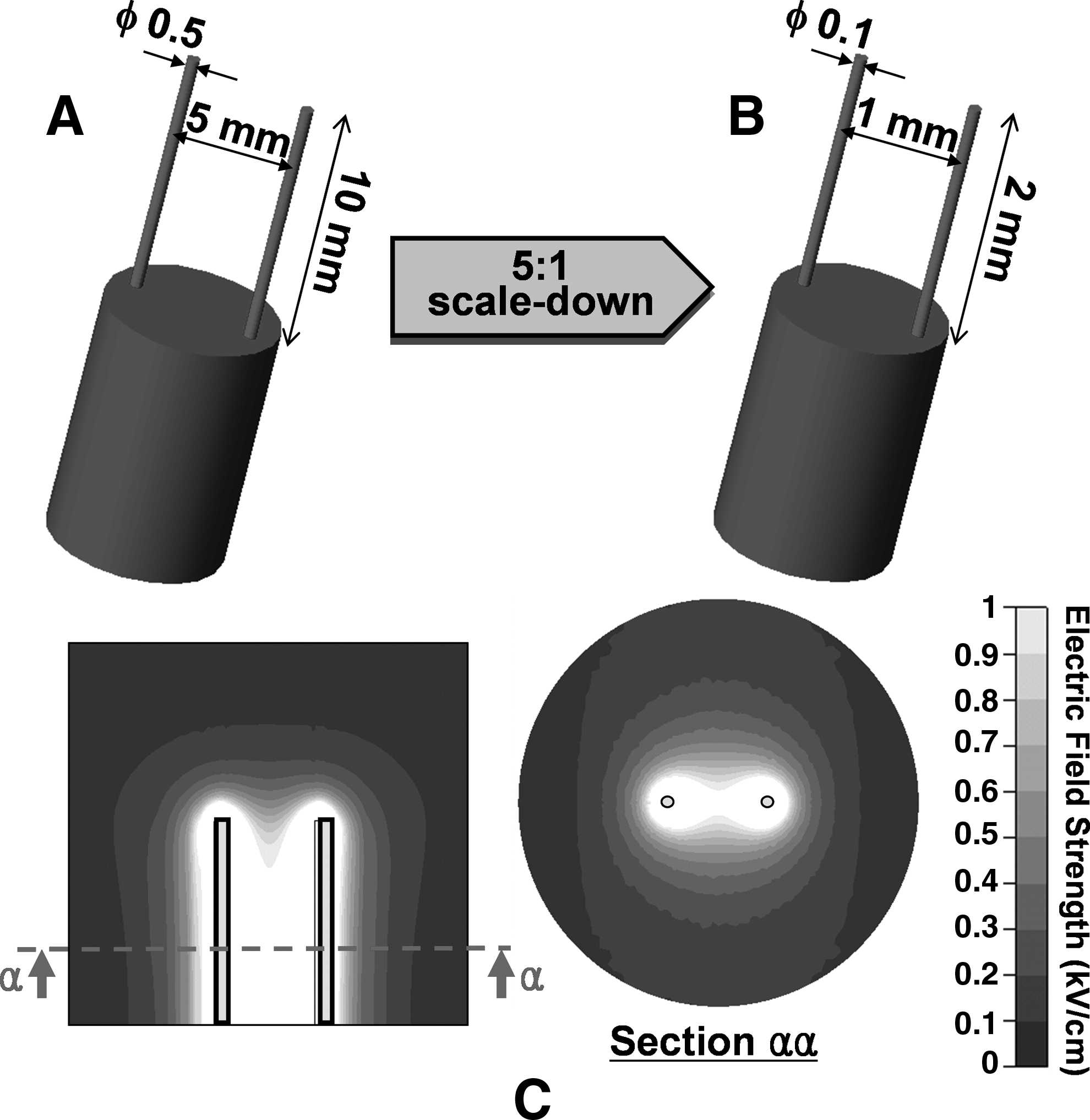
Design of an MFE and electric field distribution. Comparison of (

Fabrication process of the PDMS wire-guide in the MFE. (
An RCE was made by fixing 25-gauge syringe needles in a custom-made polymer piece having two holes of 0.5 mm diameter with 5 mm center-to-center distance. The MFE and RCE have the same electric field strength distribution as depicted in the simulation results of Figure 1C. The steady state electric field distribution was obtained by solving the Laplace equation,
where Φ is the electric potential, with a commercial simulation package (CFD-ACE+ ; ESI-CFD, Huntsville, AL). The liver tissue around RCE was modeled as a cylinder of 20 mm diameter and 25 mm height, and then the model was proportionally scaled down for the case of MFE. Fixed electric potential boundary condition was applied on the electrode surfaces, and the remaining outer surfaces were treated as electrically insulating. Despite the fact that the electric field changed somewhat along the electrode length, typical 1 kV/cm electric field strength was obtained at the middle of electrodes with voltage amplitudes of 150 and 750 V for MFE and RCE, respectively (which also maintained 1:5 ratio).
Irreversible electroporation
This study was approved by the Institutional Animal Care and Use Committee at the Seoul National University College of Medicine. Eight-week-old male Sprague-Dawley rats weighing 250–350 g were used, and all animals received humane care in compliance with the institutional guidelines of Seoul National University and current international laws and policies. 25 Rats were maintained at a controlled room temperature (24°C) with a natural day/night light cycle in a conventional animal colony and fed food and water ad libitum. They were adapted for 2 weeks to these conditions before testing.
Liver was exposed via midline incision after anesthetization with intraperitoneal injection of 10 mg/kg Zoletil (Virbac, Carros, France) solution. Electrodes were then inserted into the liver, and eight rectangular direct current pulses of 100 μs width were applied at a frequency of 1 Hz with voltage amplitudes of 150 V for MFE and 750 V for RCE using a laboratory-built pulse generator to get nominal electric field strength of 1 kV/cm at the middle of the electrodes. Up to four IRE lesions were created in a lobe for MFE, with keeping over 10 mm distance between each lesion to isolate each lesion from the effect of electric pulses of neighboring lesions, while only one IRE lesion could be created in a lobe for RCE due to the limited liver size. Every IRE treatment was conducted with new electrodes to exclude any unexpected results due to the electrochemical change on electrode surfaces. After the IRE treatment, skin incisions were sutured and the animals were kept alive up to 24 h. Liver tissues were sampled after 3, 10, 17, and 24 h of IRE, and the rats were euthanized. Liver samples were fixed in 10% (v/v) formalin solution, dehydrated, embedded in paraffin, and then sectioned in an axial cut through a plane normal to the electrode length direction. After mounting the samples on slides, H&E staining was performed to elucidate necrosis and cell apoptosis was also assessed by TUNEL assay kit (S7100; Millopore, Temecula, CA).
To quantify the degree of cell apoptosis, the percentage of stained area in TUNEL assay images was calculated, as previous area-based evaluation method in TUNEL assay,26,27 within a circular area around the electrodes (1-mm-diameter circle for MFE and 5-mm-diameter circle for RCE) by determining the area that was at least 25% darker than nonstained normal tissue area after converting the color images into gray-scale images. Image analysis was performed with ImageJ (
Electric current was measured and digitized during the application of eight electric pulses of 100 μs width and 5 kHz frequency using a current probe (TCPA300; Tektronix, Beaverton, OR) and a digital oscilloscope (TDA3044B; Tektronix) to observe the current change in tissues during EP. The same voltage amplitudes were used as the IRE operation, and all measurements were carried out in triplicate by moving into a new nontreated position each time. At the pulse frequency of 5 kHz, the fraction and resealing time of long-lived pores,28,29 and the cell viability after EP could be different from those with 1 Hz pulses. Although the influence of frequency should be validated further, we expected that the current measurement with 5 kHz pulses was reasonable for comparing the electric characteristic of MFE with that of RCE since they underwent the same frequency effect.
Thermal simulation
Temperature distribution in liver tissue was analyzed numerically with CFD-ACE+ for the characterization of Joule heating effect of electric pulses. Time-dependent tissue temperature, T, was computed by Pennes bioheat equation
30
with an additive Joule heating source term,12,31
where k (0.512 W m−1 K−1, Δk/k/ΔT = 0.25% °C−1) is the thermal conductivity of the tissue, wb (1 kg m3 s−1) is the blood perfusion, cb (3640 J kg−1 K−1) is the heat capacity of the blood, Ta (37°C) is the arterial temperature, qm (33800 W m3) is the metabolic heat generation, qj is the Joule heat, ρ (1050 kg m3) is the tissue density, cp (3600 J kg−1 K−1) is the heat capacity of the tissue, and t is the time. After solving the Laplace equation (Eq. 1), Joule heating (qj) was calculated by
where σ (0.286 S m−1, Δσ/σ/ΔT = 1.5% °C−1) is the electrical conductivity of the tissue. The tissue properties were taken from the references.12,32–34 The change of electrical conductivity caused by electropermeabilization and pore resealing was not considered.
Two-dimensional grids of 9028 triangles and rectangles were used to model an upper semicircular geometry, which included an IRE lesion and its surrounding tissue, having a five times larger diameter than center-to-center electrode distance. The bottom line of the upper semicircle was set to symmetric boundary condition. Fixed electric potential was applied on electrode surfaces with the same experimental IRE pulse condition, and outer borders were electrically insulating. All the outer borders and electrode surfaces were thermally adiabatic. It was assumed that the tissue was initially at the physiological temperature of 37°C. Implicit time integration scheme was used with time steps of 10 μs during the pulses, and 0.01 s between and after the pulses.
Statistical analysis
The differences between the mean values of groups were tested for significance by t-test after one-way analysis of variance was performed and fulfilled for all experimental data. The p-values less than 0.05 were considered significant. All mean values were obtained from at least three experiments.
Results and Discussion
Some mild degree of muscle contractions occurred during the pulse application even without any usage of muscle relaxant, and most of the rats tolerated the procedure and survived well. Nevertheless, the muscle contractions seemed to be more severe for the case of RCE than MFE, and it might be related to the one order of magnitude electric current difference between them. Electrode stiffness in the MFE was sufficient to puncture the rat liver, and mechanical failure such as buckling was not observed.
Macroscopic changes after IRE
Macroscopic images were obtained with H&E staining and TUNEL assay after 3, 10, 17, and 24 h of IRE operated with MFE and RCE, as shown in Figure 3. Clear borders were observed between IRE-treated and nontreated regions in H&E staining images throughout the observation time, while time-dependent apoptotic labeling patterns were obtained in the TUNEL assay images. These clear borders in H&E staining images were mainly attributed to pale eosinophilic cytoplasms in the treated region. Figure 4 shows the percentage of stained area in TUNEL assay with time. After 3 h of IRE, apoptotic cells were not fully labeled in TUNEL assay, despite that the IRE-treated regions were definitely distinguished from the nontreated regions both in the H&E staining and TUNEL assay images. TUNEL assay labeling reached maximum after 10 h of IRE and decreased thereafter. Stronger IRE pulse condition would be necessary for the complete tissue ablation judging from the maximum 35% stained area at most (Fig. 4), while the pulse protocol used in this study has been known to be sufficiently effective in electrochemotherapy. 35 Entire labeling patterns with MFE and RCE were quite similar until 10 h. However, the percentage of stained area showed steeper decrease in the case of MFE than that of RCE after 17 h of IRE. We speculate that this rapid decreasing rate of apoptotic cell labeling with MFE could be related to the speed of wound healing process after IRE. Irrespective of geometric proportionality, the absolute size of IRE lesion of MFE was much smaller than that of RCE, and this smaller IRE-affected area of MFE seemed to facilitate a faster wound healing than RCE as seen in microscopic images (Fig. 5). This will be further looked into in the following section on microscopic changes after IRE. Even though there was some discrepancy in TUNEL assay after 17 h of IRE, the relative extent and shape of the IRE-treated regions to electrode geometry, and the degree of apoptotic cell labeling until 10 h exhibited similar results between MFE and RCE.
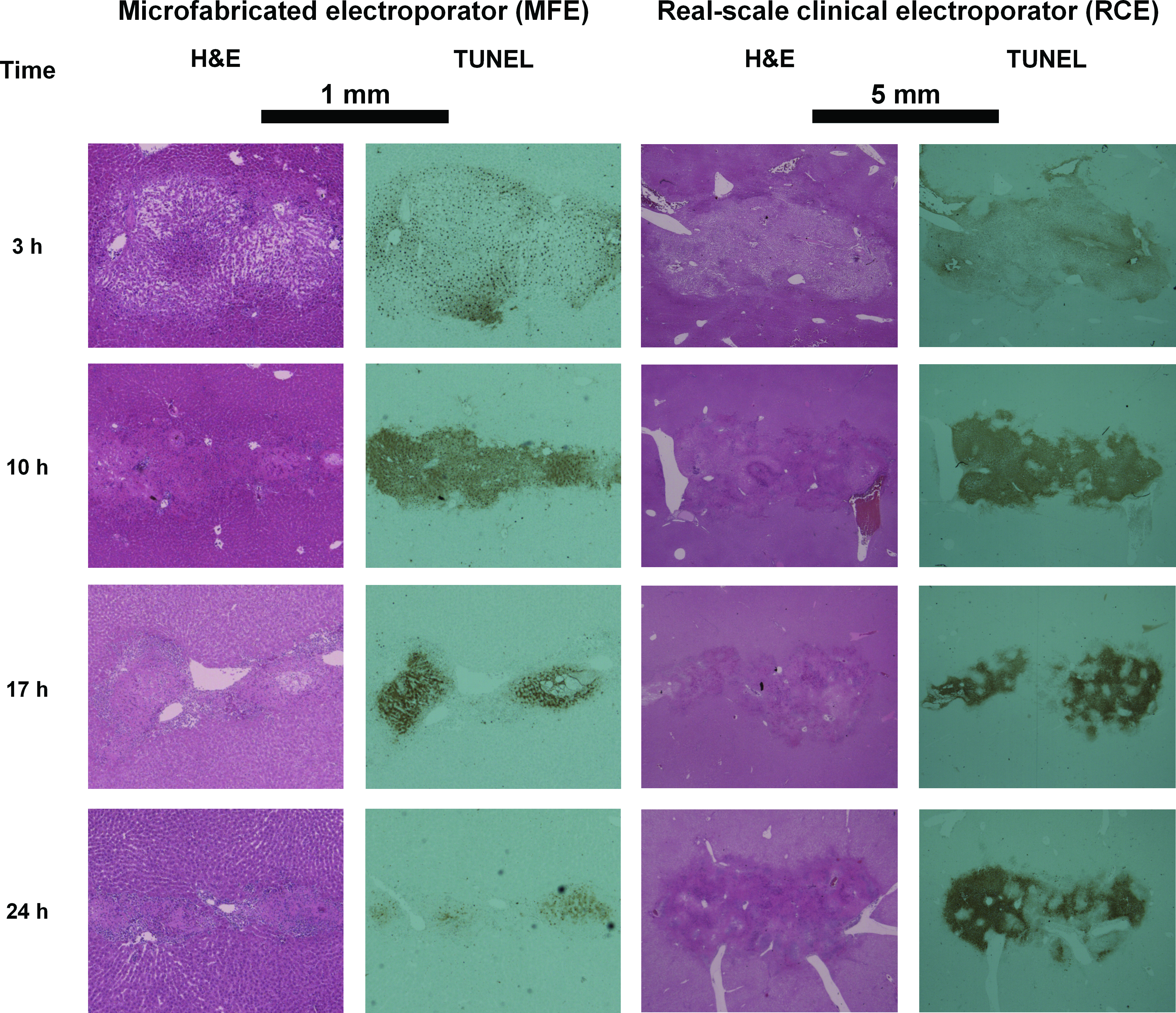
Macroscopic images of H&E staining (left images) and TUNEL assay (right images) in the MFE and the RCE, respectively. Images were obtained after 3, 10, 17, and 24 h of IRE operated with MFE or RCE. H&E, hematoxylin and eosin; TUNEL, terminal deoxynucleotidyl transferase dUTP nick end labeling; IRE, irreversible electroporation. Color images available online at

Percentage of the stained area in TUNEL assays. Color images available online at

Microscopic images of H&E staining in the MFE (
Microscopic changes after IRE
As discussed with the macroscopic images (Fig. 3), microscopic histologies exhibited sharp borders between IRE-treated and nontreated regions both in H&E stainings and TUNEL assays. The borders were obviously observed in H&E stainings irrespective of inspection time within 24 h of IRE and revealed acute damages in the IRE-treated tissues, whereas TUNEL assay after 10 h of IRE showed the clearest margination (Fig. 6A, B). Widespread pale eosinophilic cytoplasms (Fig. 6C, D) and congestion in sinusoids (Fig. 5B) were found in the treated zones, and these were the two main histological symptoms that distinguished the treated tissues from the nontreated normal tissues. Cell borders were clearly visible on the nontreated healthy parenchymas (Fig. 5A), whereas they were partly or totally ambiguous in the treated sides depending on the inspection time, which suggested cellular degeneration was underway. Other typical evidence of IRE treatment such as pyknosis of nuclei, vacuolar degeneration, massive diapedesis, and fibrin deposition in blood vessels was also observed in the treated sides (Fig. 5B, C). Endothelial damages, especially for small blood vessels, were present in the treated sides with the traces of hemorrhage (Fig. 5B, C), whereas blood vessels were intact in the nontreated sides (Fig. 5A). These histological signs, which would lead to the eventual death of hepatocytes, were in accordance with those that had been reported in the previous IRE studies on animal livers.14,16,17
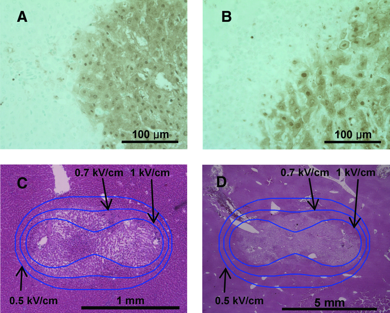
Histology in IRE lesions. (
As cell apoptosis progressed, inflammatory cells started to gather on the border between the damaged and nondamaged regions, and infiltrated gradually into the central damaged region hereafter. This phenomenon was observed from 10 h after IRE (Fig. 5D, E). After 17 h of IRE, inflammatory cells were crowded near the boundary of the treated region (see arrows in Fig. 5F, G), and they were also found after 24 h of IRE when the TUNEL assay staining was blurred in a great measure (Fig. 5H, I). These findings explain that the IRE-induced cell death was progressed with the immune cell-derived phagocytosis of apoptotic cells. In case of MFE, inflammatory cells moved easily from the boundary into the central of IRE-treated zone due to the short span of the lesion, and no traces of liver parenchyma could be seen after 24 h of IRE (Fig. 5H). On the other hand, segregated groups of inflammatory cells were observed sporadically after 24 h of IRE in case of RCE (Fig. 5I), and traces of cell borders were still found, though obscure, near the center of the IRE lesions, whereas they almost disappeared in the outer marginations (data not shown). This difference in the infiltration capability of inflammatory cells was supposed to bring about the difference in the apoptotic cell labeling of TUNEL assays after 17 h of IRE in Figure 4. However, further studies are required to make clear and elucidate the difference of long-term healing process.
It is hard to prescribe the exact electric pulse condition required to induce sufficient IRE damage due to the variance of experimental results. Nonetheless, we could find that MFE and RCE had similar threshold electric field strength of around 0.7 kV/cm in rat liver tissues with the H&E staining images superposed with iso-electric field curves (Fig. 6C, D), and this value was very similar to that of previous reports.14,36,37
Electric current measurement
Measured electric currents are plotted in Figure 7A. Although the three-dimensional electric simulation predicted that the electric current through RCE should be 25-fold higher than that through MFE, actual measured values did not show such a big difference since the relatively long electrodes of RCE compared with liver tissue went through the liver tissue completely and did not have sufficient contact area with the liver tissue for current flow. During the pulse application, electric current increased gradually as previous reports in cell pellets28,38 or tissues. 39 The electric pulses opened up nanometer-scale pores on the cell membrane, and resulted in higher electrically conductive state of the tissues. Although the current increase might be caused by both reversible and irreversible EP within the affected area, more experiments such as long-term impedance analysis are required for in-depth examination. The fact that this current increase was caused by EP on the live cell's membrane was further confirmed with additional current measurements in normal saline and pork piece, whose cell viability might be lost, and both of them did not make any current increases (data not shown). The quantity of current increase could be seen more clearly when the mean current of specific pulse was plotted after normalizing by the mean current of the first pulse (Fig. 7B). No statistical difference was found in the current increase between MFE and RCE, and the current increase amounted to as much as 10% at the eighth electric pulse.
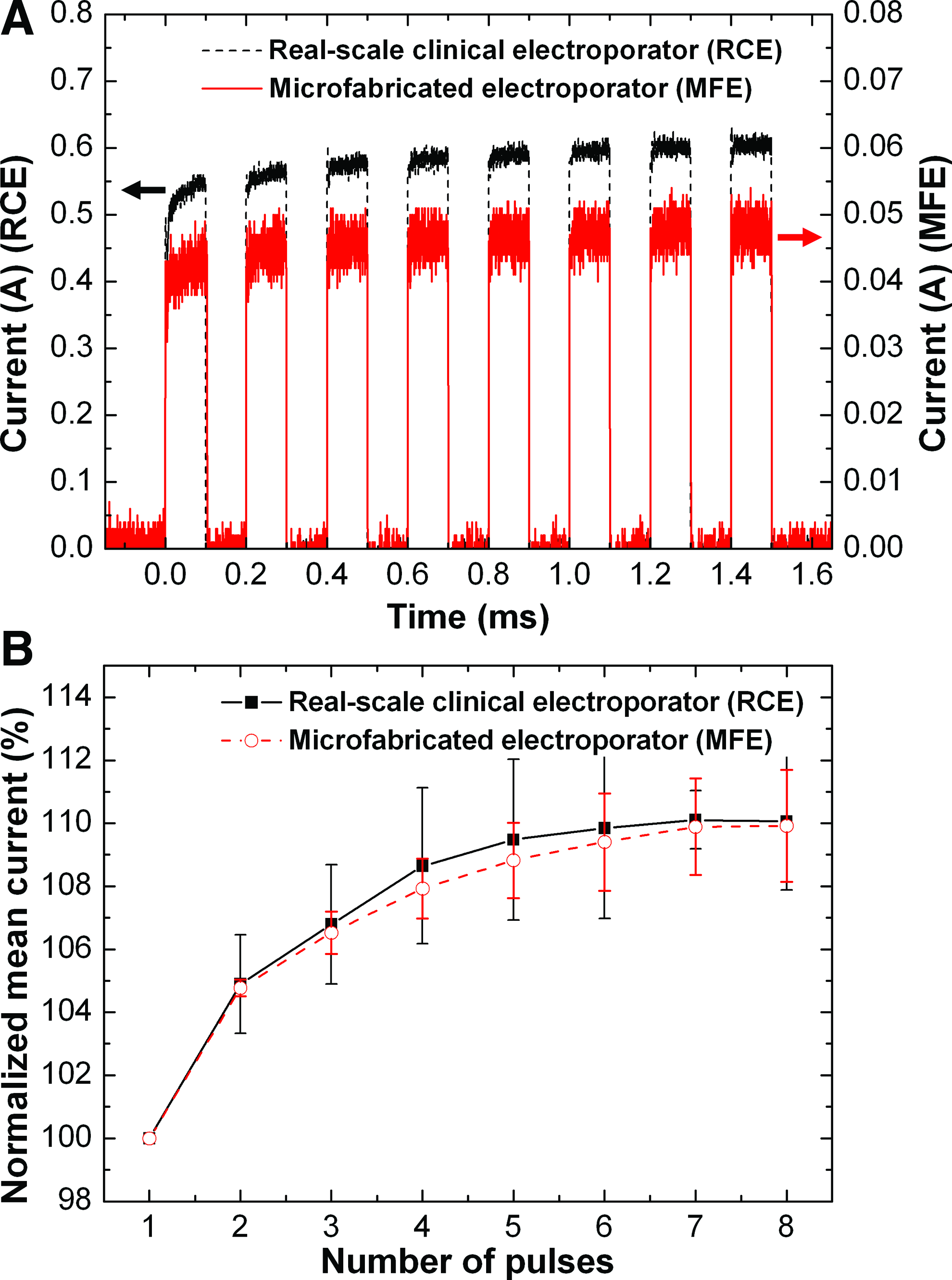
Experimental results of current measurement. (
Comparison of thermal effects on tissue-based IRE
Temperature distribution right after the end of the eighth pulse is shown in Figure 8A. Although electrode surfaces exhibited highly localized temperature rise with concentrated electric field strength, most tissue was maintained below 40°C. The average temperature in RCE case was somewhat higher than that in MFE, particularly near the electrodes. Thermal histories at points “α” in Figure 8A showed a cycle of temperature rise and drop with the pulse application, and a little higher maximum temperature was obtained with RCE (Fig. 8B). This rather higher temperature level with RCE might be attributed to slower heat dissipation depending on the size difference of IRE lesions. In a cylindrical IRE lesion, whose diameter is the center-to-center electrode distance and height is the electrode length of a two-needle electroporator, heat dissipation rate versus total heat generation is proportional to the surface-to-volume ratio of the cylinder, assuming that the heat exchange with a surrounding tissue is dominated by thermal conduction. Since RCE and MFE generate the same volumetric Joule heat (qj) under the same electric field, the heat dissipation in a lesion of MFE is five times faster than that of RCE under the 1:5 geometric ratio. Even though RCE seemed to be more prone to heat up the tissue, the maximum temperature was below 50°C, from which the tissue damage is known to increase rapidly. 40 Over 98% of the area within a circular area around the electrodes still remained below 40°C both in RCE and MFE, and even the accumulated heat diffused out within a few seconds. Judging from these, tissues might experience negligible thermal effect in RCE as well as MFE.
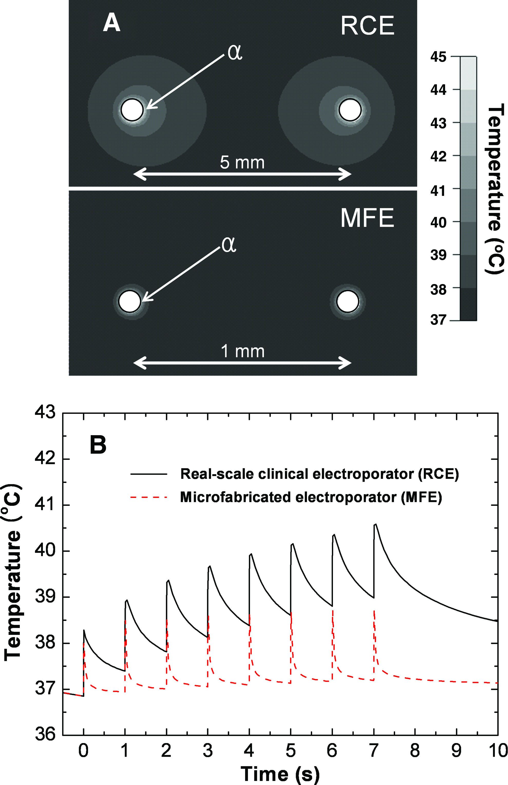
Results of thermal simulation. (
The numerical results might underestimate the temperature rise because, in real situation, the electrical conductivity of the tissue increased during EP. On the other hand, there are also various other factors to affect the thermal distribution in tissue-based EP. Tissue surfaces exposed to atmosphere may facilitate enhanced cooling by convective heat transfer, and electrode may act as a heat sink or source with its own thermal mass or Joule heating. To understand the effect of those factors in detail, the development of robust simulation model reflecting sufficient experimental data would be necessary.36,37
The rat liver tissues operated with MFE and RCE resulted in almost the same details in histology within 24 h after IRE as well as electrical change during the pulse application, whereas MFE exhibited a faster infiltration capacity of inflammatory cells than RCE. To definitely determine the limitation or extend the applicability of MFE, further post-IRE inspection would be necessary to compare the long-term tissue regeneration process. However, even in the current state, it may be useful in the study of IRE technique not only to clarify the early stage efficacy, but also to find a novel electrode configuration and the corresponding pulse mode. Of the various factors, determining the optimal electric condition to fully ablate target tissues and the maximum span to which electric pulses can exert a powerful influence are very important in clinics. However, systemic studies have not been done in IRE as with regard to these issues, and this could be a potential application of the proposed device, particularly for needle-type electroporators. From a different viewpoint, rapid prototyping methods for fabricating other types of electrode configurations should be further devised to extend the applicability of the MFE.
Conclusions
A proportionally miniaturized device of a clinical electroporator having two needles was developed by using microfabrication technology and successfully applied to the preclinical IRE study on rat liver tissues. The proposed device could reflect the characteristics of clinical electroporator quite well with regard to immunohistology and current increase during EP, while its assay procedure was more efficient in terms of time and cost than that with the corresponding RCE. Many studies have been rigorously executed for the various EP-based therapies such as IRE, electrochemotherapy, electro gene therapy, and nanosecond pulsed electric fields to examine the effect of the treatments and to set up the standard operating procedures since EP was recognized as one of the plausible methodologies to ablate tumors locally. However, there are still lots of tasks that should be unveiled for the successful clinical applications not only in empirical aspect but also in basic theoretical aspect. In this respect, we expect that the proposed MFE can serve as an enabling tool in the preclinical studies of EP-based therapies to reduce the required research resources and endeavor.
Footnotes
Acknowledgments
This work was supported by the National Research Laboratory Program (Grant no. R0A-2008-000-20109-0) funded by the Ministry of Education, Science and Technology (MEST), Korea. The authors also thank the Clinical Research Institute of Seoul National University Hospital.
Disclosure Statement
No competing financial interests exist.