
Abstract
Rapid prototyping techniques are widely used to fabricate well-defined three-dimensional structures of tissue homologs. The piston-assisted microsyringe (PAM2) is a rapid prototyping technology specifically developed for low-shear stress extrusion of viscous hydrogel solutions containing cells. In this article the working parameters of the system were established to guarantee the realization of spatially controlled hydrogel scaffolds. Moreover the shear stresses acting on the cell membrane during extrusion was investigated through a computational fluid-dynamic analysis. The computational models show that the shear stress on the cells is of the order of 100 Pa during the extrusion process. HepG2 cells encapsulated in alginate were then extruded into spatially organized hepatic lobule-like architectures and their viability and function were evaluated. The results show that the metabolic fingerprint of the cells is preserved with respect to controls and the cells are uniformly distributed through the gel scaffold.
Introduction
Hydrogels are a natural choice for these applications; not only are they highly biocompatible, but also they have a high water content (similar to soft tissues), but often their mechanical properties can be finely tuned.2,3 One of the most well-known and widely used hydrogels is alginate, which consists of a cross-linked network of polysaccharides interpenetrated by water. 4 Physical cross linking is usually performed by adding calcium ions to a sodium alginate solution. The consistency of the gel depends on several parameters such as the initial concentrations of sodium alginate and calcium, the cross linking time as well as the aqueous environment. 5 Alginate hydrogels have been widely employed in tissue engineering applications, including blood vessel networks 6 and neural tissues 7 and are also used to encapsulate cells such as β-islets 8 and hepatocytes. 9 Falasca et al. 9 reported that encapsulated hepatocytes rapidly establish cell polarity and form cohesive junctions, probably because the cells are furnished with a 3D environment.
Rapid prototyping (RP) methods based on computer-aided design (CAD)/computer-aided manufacturing systems are employed to obtain a high degree of control over the geometrical features of a 3D scaffolds.10–13 Given their soft-wet-floppy nature, hydrogels are considered quite difficult and messy to process into organized 3D structures. Landers et al. 14 pioneered gel fabrication using a pressure-actuated syringe-based method to fabricate agarose structures with 0.5 mm resolution. Boland et al. 15 and Mironov et al. 16 use inkjet printing methods to deposit cells onto alginate gel surfaces. More recently, Nishiyama and Nakamura 17 demonstrate that inkjet printing can also be used to print alginate gels with encapsulated cells, with a resolution of about 100 μm, although cell viability in the conditions described is somewhat questionable. Sun and coworkers, 18 have reported on a pressure dispensing system whose working principal is similar to the pressure-assisted microsyringe (PAM) system 19 to extrude alginate hydrogels incorporated with cells. Although no data on CAD, resolution, or fidelity are reported, their work shows that the cells are damaged by the high pressure (~250–2000 mmHg) extrusion process, but the damage is partially (~50%) recovered after 24 h. The phenomenon is attributed to mechanical forces acting on the cells during the extrusion process.
To realize well-defined hydrogel structures, our PAM microfabrication system has been adapted to hydrogels, and we have shown that the extrusion pressures used with this system are not sufficient to process viscous materials or gels. 20 Since viscosity is one of the key parameters that define the resolution of extrusion or drop-based RP microfabrication methods, in 2008 we developed a proprietary biomaterial fabrication system, piston-assisted microsyringe (PAM2). In PAM2 we combine RP procedures with microencapsulation techniques to print viable well-defined structures of highly viscous materials containing cells or other particles. 21 Instead of using pressure, a mechanical piston is used as the driving force for extrusion, allowing the application of low shear stresses over short time periods to cells during ejection. CAD software was specifically developed to design scaffolds that are printed into 3D gels with encapsulated cells through a layer-by-layer process. In this article we present the principal features of this system and the geometrical characteristics of the scaffolds as a function of the PAM2 working parameters, using alginate as the carrier gel. Moreover we consider a critical aspect of extrusion or drop-based deposition of cell-incorporated gels: the mechanical force acting on cells during the fabrication process. A finite element model (FEM) of the extrusion method was thus implemented for the evaluation of the shear stress acting on the cell membrane during the RP process. Finally, we fabricated well-defined hexagonal hydrogel scaffolds with encapsulated hepatocytes (HepG2). Viability and functional tests were carried out to analyze how the extrusion process influences cell function, while cell distribution within the scaffolds was observed using fluorescent labeling.
Materials and Methods
HepG2 cells (a human hepatocellular liver carcinoma cell line) were a kind gift from Dr. Maurizia Brunetto and used at the same passage in all experiments, while minimum essential medium (MEM) and its additives were purchased from Invitrogen. Unless otherwise specified all other materials and reagents were from Sigma-Aldrich.
Alginate solution
Solutions of sodium alginate (powdered alginic acid sodium salt from brown algae, A0682) were prepared in phosphate-buffered saline (PBS) solution (i.e., 4% and 6% w/v). These high-viscosity solutions were necessary for the fabrication of spatially controlled scaffolds, as explained in the section on working parameters. The solutions were sterilized by autoclaving, which serves to partially break polymer chains and reduce swelling. The stiffness of gels depends mainly on the gelation process and is not greatly altered by autoclaving as it remains within the range 10–100 kPa in the cross-linking conditions used. 22 A 0.5 M solution of calcium chloride in MilliQ water was filtered with a 0.22 μm pore filter before use as a cross-linking agent.
HepG2 cell line
HepG2 cells were cultured in MEM, supplemented with 5% (w/v) fetal bovine serum, 2 mM of L-glutamine, 100 μg/mL of streptomycin, 100 U/mL of penicillin, 5 mL of MEM nonessential aminoacids 100 × solution, and 5 mL of MEM vitamins and maintained in an incubator at 5% CO2 and 37°C.
PAM2 system
The PAM2 system was designed to fabricate well-defined 3D scaffolds using materials with high viscosity, typically hydrogels, and can be considered as an evolution of the pressure-activated microsyringe (PAM). 19 The original syringe-based PAM system uses compressed and filtered air to extrude liquid materials or solutions through a fine bore needle onto a horizontal XY deposition plane. The PAM system can only process solutions with viscosities which range from 0.1 to 1 Pa · s. Hydrogels that have viscosities which may go up to 8 Pa · s cannot be safely extruded by the application of air pressure. For this reason PAM2 was designed with a fourth controlled stepper motor added to the 3D micropositioning system. This stepper motor actuates the piston of a commercial syringe, allowing control of the outflow of material from the needle tip (as shown in Fig. 1). The mechanical structure of the PAM2 system therefore supports three XYZ brushless motors (BMS60; Aerotech, Inc.) with a spatial resolution of 0.15 μm, and a specially designed framework to hold a commercial syringe. Another smaller stepper motor (Z1) drives the plunger (i.e., the pressure applied to the syringe depends on the velocity of the plunger). In this work all experiments were carried out using a 10 mL, 29 gauge needle plastic syringe (BD Plastipak™; Becton Dickinson Italia SPA, nominal internal diameter 165 μm). An additional feature of the new system is that it is small and compact and can be used with a disposable syringe in a sterile environment (laminar flow hood). Cells can therefore be suspended in the solution and processed with the PAM2 system. Moreover, a CAD software interface was developed to design and control the architecture of 3D scaffolds, allowing interactive control of the principal working parameters during fabrication.
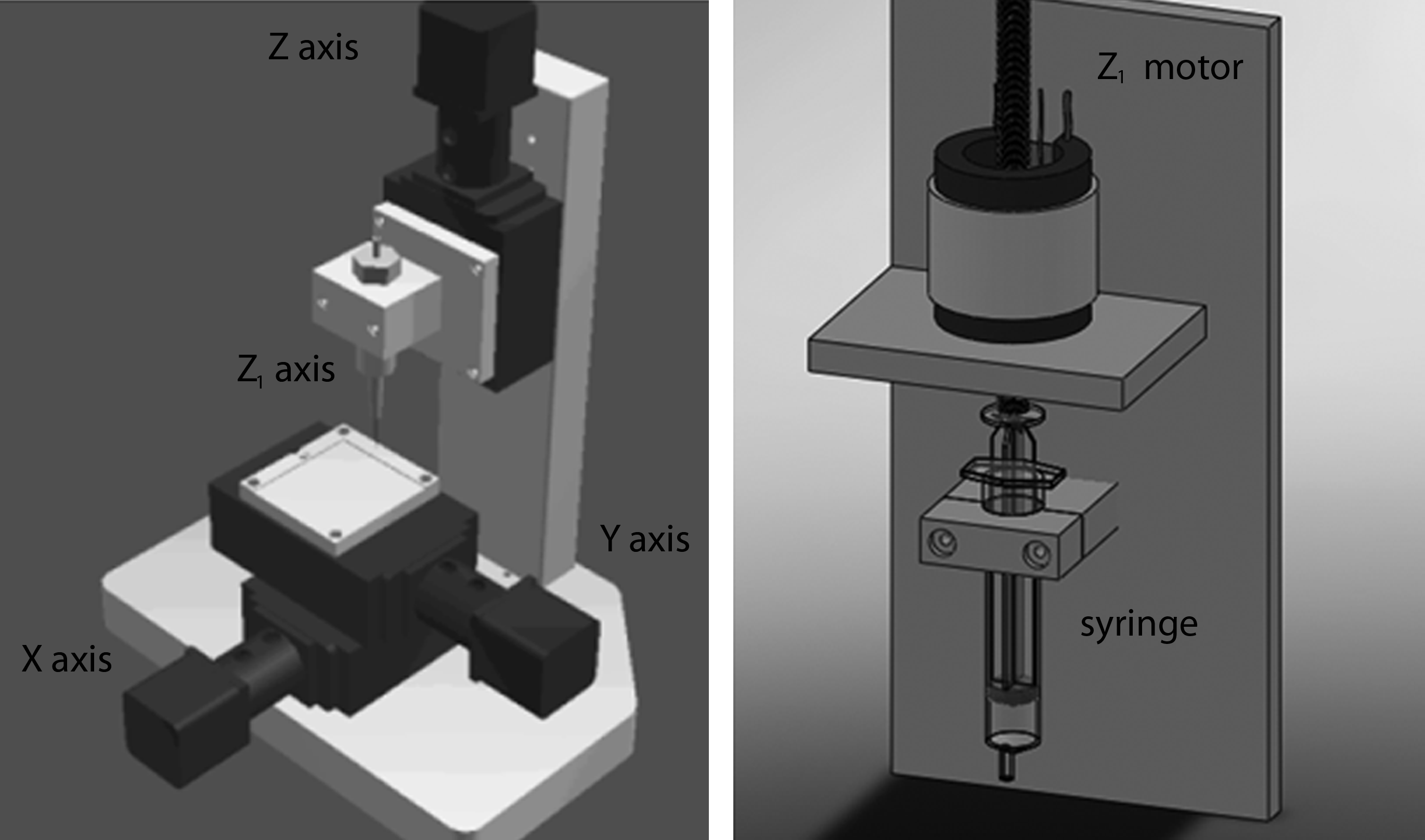
Mechanical design of the PAM2 system showing the three-axis high-resolution micropositioner (spatial resolution of ±1 μm each); and details of the fourth axis (Z1) stepper motor used to control the extrusion of material through a commercial syringe. PAM2, piston-assisted microsyringe.
Establishment of working parameters
Typical working parameters of the PAM2 system are the velocity of the stepper motor Z1, which drives the syringe piston (determining the material outflow), and the velocity of the XY micropositioners (or the deposition velocity, DV). Both these parameters together determine the line width (LW) and fidelity (with respect to the CAD) of the scaffolds. However, the actual quantity of material flowing through the needle for a given velocity depends on its viscosity as well as the surface tension between the needle and the fluid. Since material outflow versus velocity profiles differ according to material properties, a preliminary characterization to establish a useful working window for processing viscous materials has to be performed for each material and needle used. Different sodium alginate concentrations with different viscosities (values between 2 and 8 Pa · s) were extruded as a function of the stepper motor angular velocity ω1, and both material outflow and resultant linear Z1 piston velocity were measured. Outflow was measured by extruding the material onto a glass slide placed on a digital microbalance (Mettler; Mettler Toledo, acquisition frequency 2 Hz) interfaced to a computer.
The second typical working parameter, the DV, determines the LW of the extruded material for a given outflow. In the PAM2 system, the DV can be varied up to a maximum of 10 mm/s. To characterize the scaffold dimensions as a function of both LW and outflow, two sets of experiments were performed. First, the deposited LW was characterized as a function of the material outflow for a fixed DV. Successively, the LW was characterized as a function of the DV for a fixed outflow. Tests for LW characterization were performed both for the 4% and the 6% alginate solution in PBS. For the first series, the DV was fixed at 4.0 mm/s, whereas the material outflow was fixed at 12.7 and 4.2 μL/s (respectively, for alginate solutions of 4% and 6%, with ω = 0.2512 rad/s). Immediately after deposition, 1 mL CaCl2 cross-linking solution was pipetted over the scaffold, and after a few minutes the solution was rinsed with MilliQ water. The cross-linking procedure is critical not only because an un-cross-linked alginate solution will spread, but also because it determines the mechanical properties of the scaffold. Therefore, in this article the LWs are always referred to the cross-linked gel. The LW was measured with an optical microscope (Olympus AX70) with a 20 × objective.
Alginate scaffolds
Before incorporation of cells, two simple scaffold geometries were designed with the CAD software and fabricated on a glass coverslip in the form of a square and hexagonal grid, respectively. The working parameters for the square grid scaffold were a DV of 4.5 mm/s and an outflow of 9 μL/s (previously characterized for a 6% w/v alginate solution). The grid elements were 7 × 7 (rows by columns) with a final scaffold dimension of 8 × 8 mm and a total alginate solution volume of 190 μL. With these parameters, an LW of about 700 μm was realized and the estimated height of the scaffold was 2 mm. For the fabrication of hexagonal scaffolds the parameters were set to DV = 4.5 mm/s and an outflow of 4 μL/s. The hexagonal units had sides of 600 μm. After cross-linking, the final dimensions of this scaffold were 7 × 6 mm with an LW of 400 μm. A total volume of 80 μL of alginate solution was employed, and based on this we estimated the height of the scaffold to be 1 mm. Observations with an optical microscope confirmed that well-defined (LW was within ± 20% of the mean) and high-fidelity (well-shaped, faithful representations of the CAD image) scaffolds were obtained for both the hexagonal and square topology. Figure 2 shows examples of alginate scaffolds obtained using a 6% w/v sodium alginate solution cross-linked with 0.5 M CaCl2.

Examples of hydrogel scaffolds realized with PAM2 system. Six percent w/v alginate dissolved in phosphate-buffered saline is extruded using an outflow of 9 μL/s, deposition velocity of 4.5 mm/s, and then physically cross-linked with 0.5 M calcium chloride solution.
Cell-incorporated alginate scaffolds
Once the working parameters of the PAM2 system have been established, the number of cells incorporated into each scaffold can be simply controlled by adjusting the cell concentration in the alginate solution and the outflow through the syringe. To mimic the hepatic lobule, hexagonal alginate scaffolds were used for incorporation of hepatocytes. When at 80% confluence, cells were detached with trypsin, counted with a hemocytometer, and then gently suspended in 6% (w/v) alginate solution in PBS to a final concentration of 4 × 10⁶ cells/mL. A syringe was then filled with the cell suspension, and mounted on the PAM2 system placed under a sterile laminar flow hood. The scaffold volume was controlled to maintain a constant cell number per sample; in particular, about 200,000 cells were included in each scaffold. Alginate and cells were extruded onto a sterile 13-mm-diameter coverslip and immediately after cross-linking the slide and scaffold were transferred to a 24 multiwell plate, covered with 1 mL of medium and incubated at 37°C and 5% CO2. As a control the same total volume of sodium alginate with cells (concentration of 4 × 10⁶ cells/mL, volume 80 μL) was pipetted using a P100 Gilson micropipette (Gilson Italia) in a 24 multiwell plate and cross-linked using 1 mL of 0.5 M CaCl2. Two different scaffolds with hexagonal topology were designed using different piston velocities, V1 and V2, corresponding, respectively, to a 6% w/v alginate outflow of 4 and 9 μL/s.
Cell tests
Cell viability and metabolic tests were performed on samples collected at different times, respectively, at 6, 24, and 48 h after scaffold fabrication. Viability was measured using the Cell Titer-Blue-Cell Viability Assay (Promega), based on a resazurin-based compound metabolized by mitochondrial cytosolic enzymes to resorufin, which can be detected with a fluorimeter. Viability is generally proportional to vital cell number as confirmed by routine calibration of viability versus hemocytometer counting. Glucose (Megazyme International Ltd.) and albumin (Bethyl Laboratories Inc.) were assayed using commercial Elisa kits according to the manufacturer's instructions. To observe the 3D localization of cells in the scaffolds, cells were stained with 4′, 6-diamidino-2-phenylindole (DAPI). The samples were washed with PBS, fixed with 4% formaldehyde solution, and stained with 1 μg/mL of DAPI for 5 min. Scaffolds were observed under a fluorescent microscope for analysis.
FEM analysis
A well-known problem affecting cell viability during high-velocity extrusion in viscous materials is the shear stress that acts on the cell membrane. To quantify the shear forces acting on the cells, a FEM analysis of the extrusion phase of cells through the syringe needle was performed with Comsol Multiphyiscs Software (COMSOL). The model considers two immiscible fluid phases: (1) spherical cells of 50 μm diameter and (2) a bulk alginate phase. The incompressible Navier-Stokes equations (Equations 1 and 2) were applied to the bulk fluid domain (alginate) and cells using the Level Set Two-Phase Method, an application in COMSOL.
where ρ is the fluid density, η is the dynamic viscosity,
The interface is represented by a certain level set (or isocontour) of a globally defined function, φ, a smooth step function that equals zero in one domain or phase and one in the other. Across the cell membrane/alginate fluid interface, there is a smooth transition from zero to one, so that the interface is defined by the 0.5 isocontour. Using this value the interface between cells and fluid can be tracked. Specifically, the first part of the right hand side of Equation 3 is necessary to give the equation of motion to the interface, whereas the second part is required for numerical stability. Two parameters influence the function φ: ɛ determines the thickness for the smoothing transition of φ (and should be of the same order of the mesh size), and γ determines the stabilization of the level set function (to prevent oscillation, a suitable value is the maximum magnitude of the velocity field
Statistical analysis
Statistical analysis of cell viability and metabolism was performed using the Student's t-test and analysis of covariance (ANCOVA, Matlab Statistics Toolbox; The MathWorks Inc.) for the comparison of slopes; a p-value of <0.05 was considered statistically significant. For the cell viability and metabolism data, each data point is represented as the mean and standard error of at least three samples, whereas the LW measurements are given as means and standard errors of at least 10 optical measurements per scaffold.
Results
Outflow and LW characterization
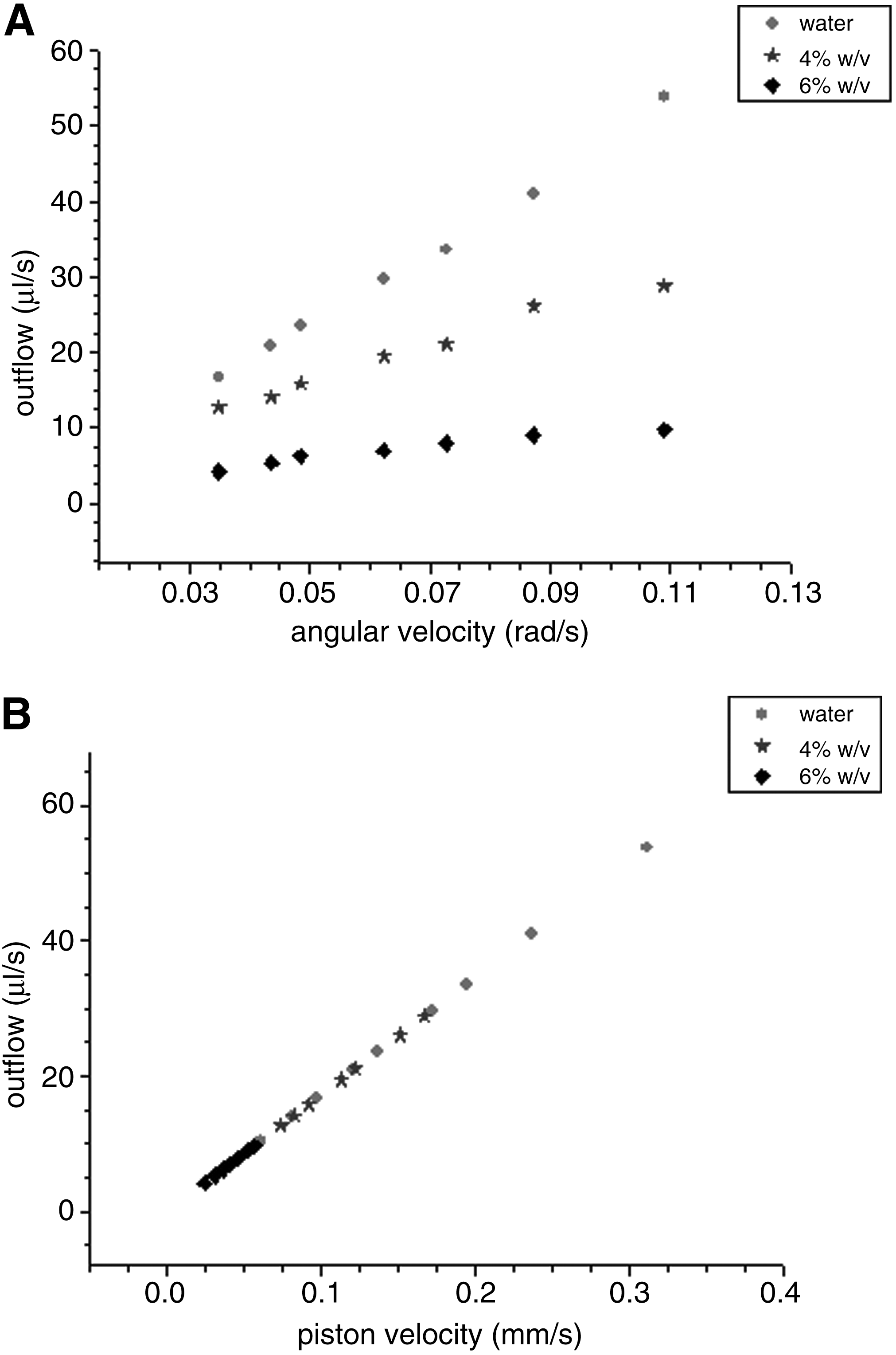
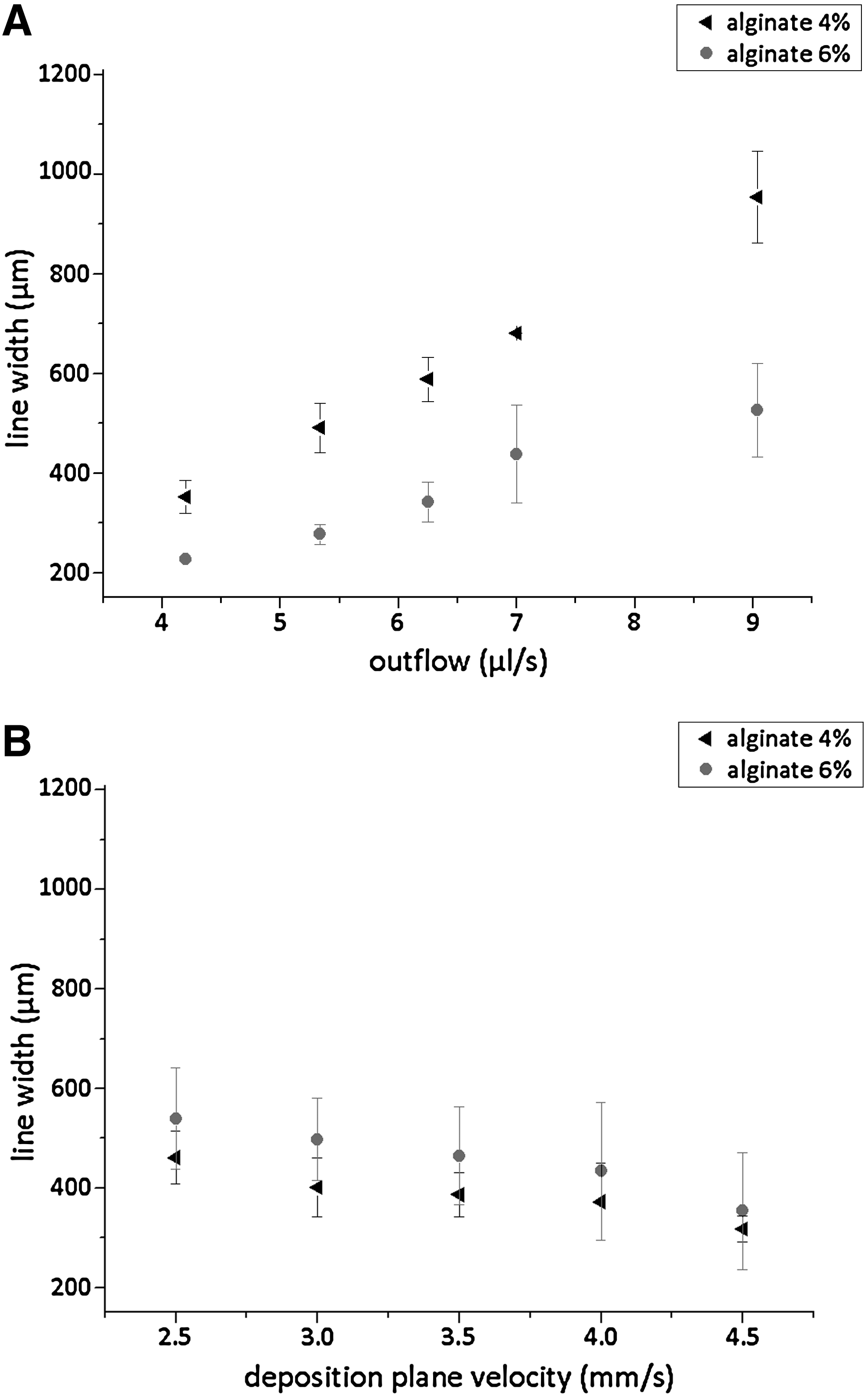
In extrusion-based RP techniques the material outflow and the DV determine the resolution of microfabricated structures. First, we determined material outflow for a given angular velocity of stepper motor Z1. Figure 3A shows how the viscosity of the material influences the outflow for a given angular velocity, whereas Figure 3B underlines the linear relationship between linear velocity of the piston and the outflow through the needle. This latter result demonstrates that no losses occur during the fabrication process, and that the hydrogels behave like Newtonian fluids at the pressure gradients applied. During the second set of experiments we analyzed the LW as a function of outflow and DV. As shown in Figure 4A there is a marked increase in LW with an increase of material outflow, whereas an increase of DV corresponds to a slight decrease in LW (Fig. 4B). Therefore, the main working parameters are outflow and gel viscosity. Due to the lower outflow, the scaffolds realized with V1 are of higher fidelity and lower LW than the ones obtained with V2. In addition the scatter in the LW measurements is greater for the 4% than for the 6% alginate solution, particularly at high outflows. This is because the 6% solution is more viscous and thus the drop size at the needle tip is smaller. Smaller drops and higher viscous forces on the needle tip produce lines that spread less on a glass surface. 20 As a consequence the 6% solution extruded at outflow V1 produces the highest fidelity structures with good control in LW and shape (Fig. 2).
FEM analysis: Evaluation of shear stresses on the cell membrane
Cells and, in particular, hepatocytes are extremely sensitive to the shear stress acting on their membrane. 26 A fluid-dynamic analysis of the extrusion phase was therefore performed to evaluate the shear stress acting on the cell membrane due to the interaction between the polymer solution and the suspended cells. First, we analyzed the fluid-dynamic model of the entire syringe to evaluate the critical area in which the shear stress acquires significant values. Results show that syringe needle (as expected) is the most critical zone of the system; the main reason for the increase of the velocity field in the needle domain is the abrupt narrowing of cross section. To predict the shear stresses acting on cell membrane, a purposely designed model was then performed in the region between the syringe barrel and the needle. Using the Level Set Two-Phase Flow method (in MEMS fluid-dynamics mode in COMSOL), we analyzed the behavior of a cell, modeled as a sphere of immiscible fluid immersed in alginate solution, as it moves through the syringe needle. The model illustrates that viscous forces deform the cell membrane and reach values of about 200–350 Pa in the first 10 μs as the cell enters the needle (Fig. 5A and B). The values of shear stress calculated are extremely high compared with physiological values in arteries (0.1–1 Pa), and certainly much higher than those reported to be tolerated by hepatocytes (0.05 Pa). 27 However, shear stresses act on the cell surface for a less than half a second as it passes through the needle, whereas the values quoted above refer to constant shear stress over long periods. The maximum shear stress imposed by the PAM2 method is, nevertheless, much less than other gel-based printing systems such as inkjet printers 15 and direct cell writing 28 and is therefore particularly suited for incorporation of cells. We also compared the time dependence of the shear forces developed during extrusion for the two outflow velocities, in Figure 5C. The piston begins to move at time 0 and there is an immediate increase in shear stress; the shear stress quickly drops to zero after less than half a second once the cell exits the needle. In outflow V1 (4 μL/s) the maximum shear force is less than in outflow V2 (9 μL/s) but cells remain in the syringe for a longer time. Numerical integration of the curves gives the total impulse per unit area, which could be used as a measure of the cumulative damage to cells during extrusion. The lower outflow velocity delivers a higher impulse per unit area on the cells: 27.65 Pa/s for V1 and 18.05 Pa/s for V2.
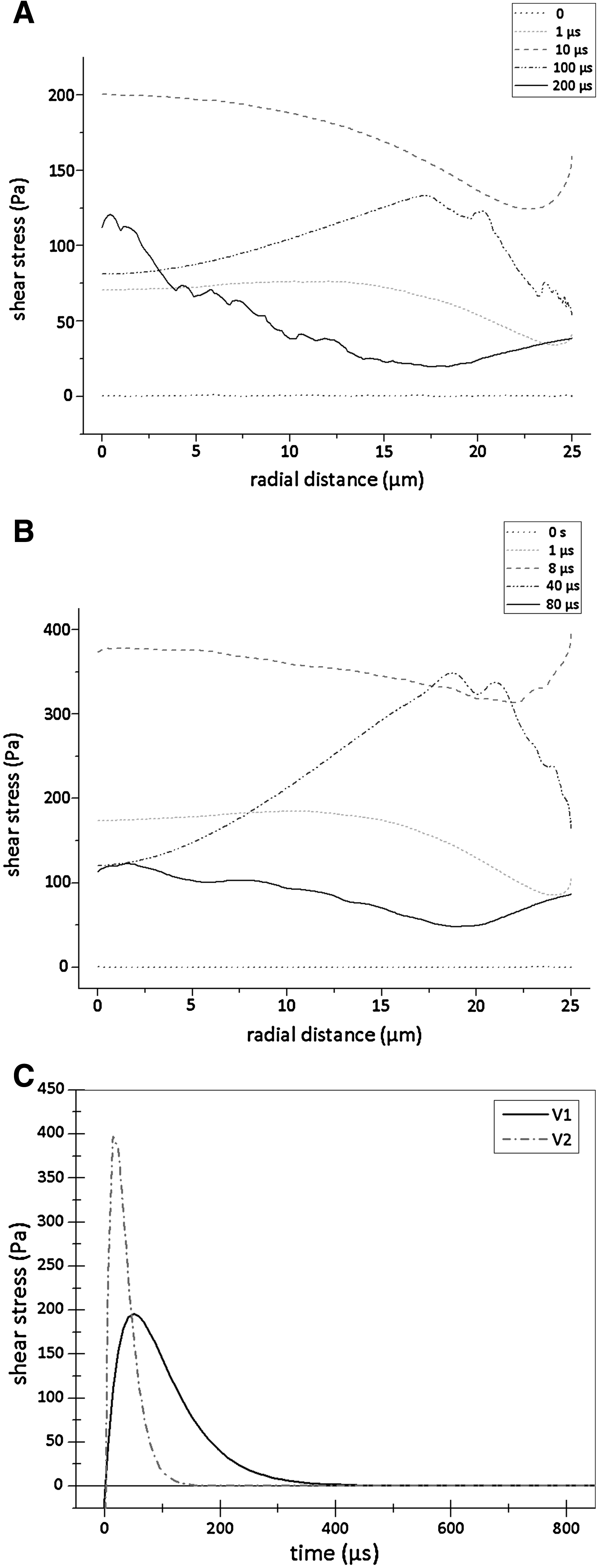
The shear stress acting on the cell membrane during its passage through the needle (internal diameter of 165 μm) at different times using the finite element model analysis.
Cell tests
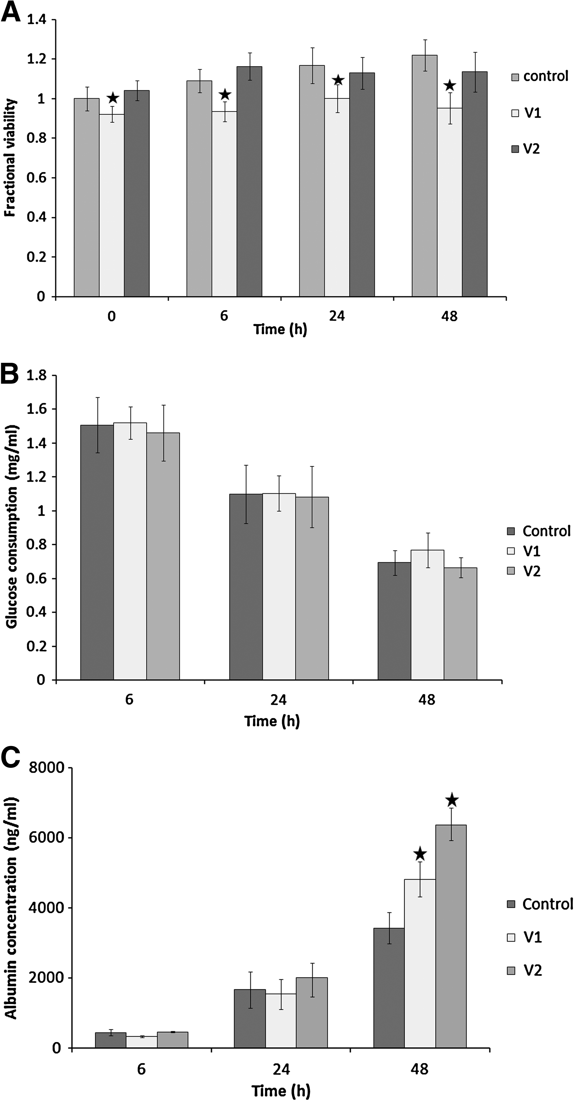
To assess the effect of the extrusion process on cells, in this study we evaluated cell proliferation and metabolic profiles of HepG2 cells encapsulated in 6% v/w alginate scaffolds using different outflow rates (V1 and V2 corresponding to 4 and 9 μL/s, respectively). Cell viability over 48 h was analyzed with the Cell Titer-Blue Viability Assay (Fig. 6A). As shown, cell viability of controls is similar to that of cells extruded with outflow V2 (comparison of control and V2 slopes p = 0.068 ANCOVA), while it is slightly but significantly decreased for outflow V1 (comparison of control and V1 slopes p = 0.041 ANCOVA). Glucose consumption, reported in Figure 6B, was similar in controls and scaffolds, with a steady decrease in time. Cell viability and glucose consumption furnish important but only general information on hepatic function. For this reason a hepato-specific marker, albumin, was also analyzed. Albumin synthesis per cell increased rapidly after 24 h, and after 48 h was significantly increased in the scaffolds, particularly in the case of V2 (Fig. 6C). Therefore, the scaffolds provide a better microenvironment for the expression of this protein. The results indicate that the extrusion process using outflow V1 causes some cell damage since viability decreases and cells do not appear to proliferate even after 48 h, although their capacity to synthesize albumin is increased. On the other hand, in the cells extruded with velocity V2, the cells proliferate at similar rates to controls and hepato-specific functions are also upregulated. Analysis of DAPI stained cells in the scaffolds showed that cells were uniformly distributed at different levels in the scaffolds (Fig. 7) and the nuclei remained intact. Overall, the higher outflow velocity seems more effective at maintaining cell viability and high metabolic function and cells appear to be better distributed with higher density in the scaffolds.
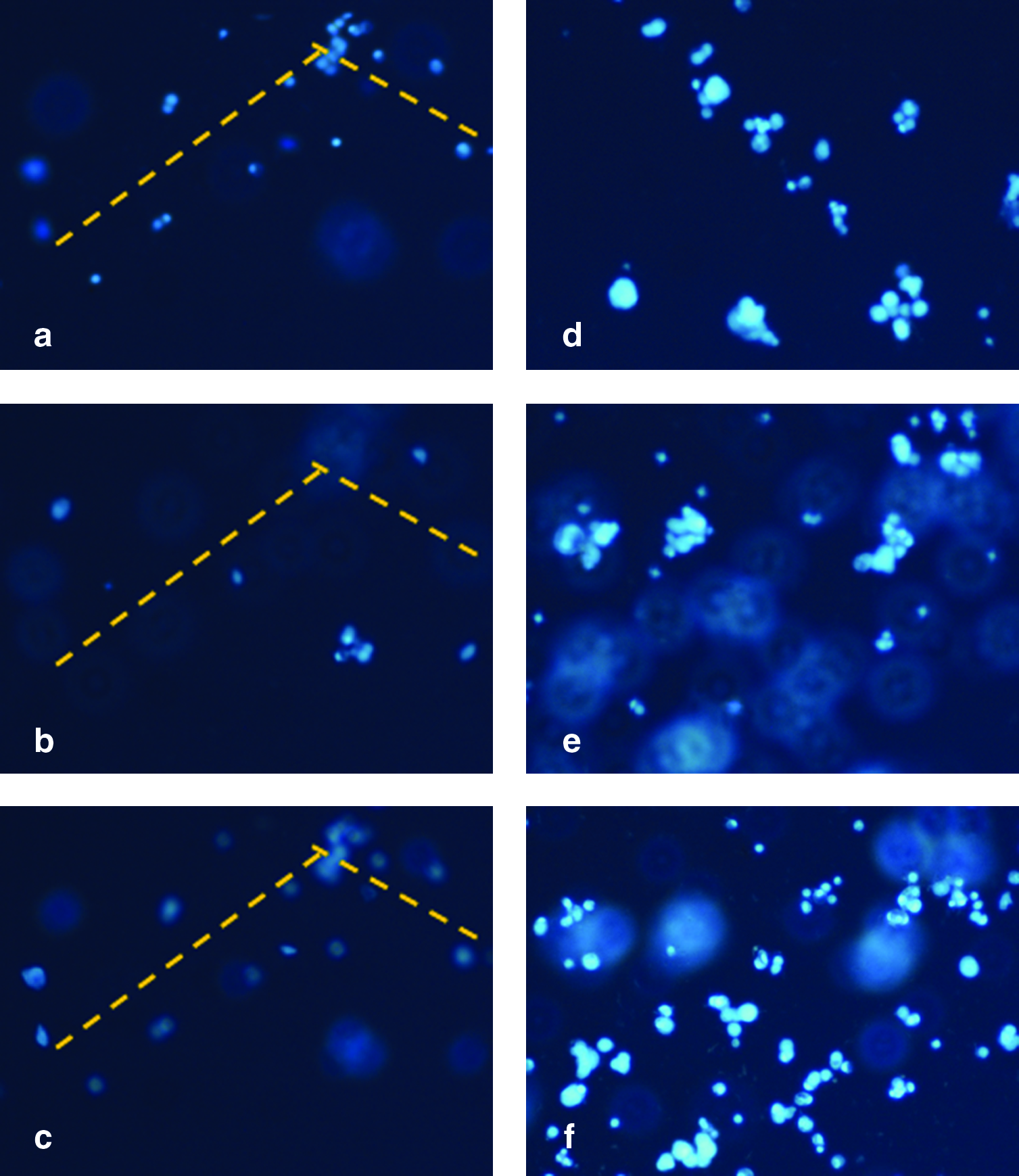
Three-dimensional observation of DAPI-stained encapsulated HepG2 in alginate scaffolds at different heights after 48 h of incubation. Cell distribution at different depths in scaffolds realized with
Discussion
Several reports describe the microfabrication of cell-incorporated hydrogels using RP technology, such as ink-jet printing and direct cell writing.15–18 The techniques used enables small drops of gel to be printed in defined locations, but the final result is, nevertheless, a uniform volume of material with no open pores or overhangs. Using these results as a starting point, we designed the PAM2 system, which uses a piston to control the extrusion of viscous materials, such as hydrogels, through a needle for the realization of microstructures. Using alginate as a typical biocompatible gel, we characterized the LW and spatial resolution as a function of the working parameters. First, we established the optimum range of sodium alginate concentrations, which could be used for extrusion. On the basis of viscosity measurements, 4% and 6% (w/v in PBS) were chosen as suitable alginate concentrations. Using these solutions the width of the deposited hydrogel lines was evaluated as a function of material outflow and velocity of the XY deposition plane. The outflow of material depends strongly on its viscosity and on the frictional forces between the gel and the walls of the needle (surface tension), as well as on the force applied by the piston. Our results show that well-defined shapes and high spatial resolutions can be obtained with more viscous solutions, and that the lower the outflow, the higher the scaffold fidelity. Since most cells, particularly hepatocytes, are very sensitive to shear forces it is important to minimize any cell damage during the fabrication process. To quantify the forces acting on the cell membrane, an FEM simulating the shear stress acting on the cell membrane during the extrusion process was solved using Comsol Multiphysics. The results obtained indicate that cells are subject to fairly high shear stresses of the order of a few hundred pascal for a short period of time, and this causes cell deformation. The impulse per unit area for two the different extrusion velocities was also evaluated; interestingly, the lower outflow velocity delivers a higher impulse per unit area to cells. On the basis of these results, we fabricated biomimetic hexagonal scaffolds by extruding hepatocytes suspended in sodium alginate (6% w/v) using two outflows, V1 and V2. The scaffold shape was fixed by cross-linking with CaCl2 (0.5 M for 5 min) immediately after deposition to obtain a well-defined hepatic lobule-like architecture. Both cell viability and metabolite production were assessed and compared with controls in which HepG2 cells suspended in alginate did not undergo the extrusion process. In the case of the lower extrusion outflow V1, cell viability was compromised with respect to controls. The results of the FEM model show that this outflow delivers a higher impulse per unit area to cells. On the other hand, after 48 h, albumin production was significantly upregulated in all scaffolds with respect to the controls. The results suggest that the extrusion process can compromise cell proliferation, but hepato-specific function is increased, possibly because the porous scaffold allows efficient nutrient exchange while providing an organized 3D architecture to cells. In conclusion, in all extrusion or drop-based methods there is a trade-off between scaffold fidelity and cell viability; high viscosity solutions and low outflows enable the fabrication of high fidelity scaffolds, but these parameters, respectively, increase the magnitude and duration of shear forces during extrusion.
Footnotes
Acknowledgments
A.T.'s Ph.D. fellowship is funded by Italian Ministry of University Research, through the University of Rome “Tor Vergata.”
Disclosure Statement
No competing financial interests exist.