
Abstract
The present study describes the design and validation of a simple apparatus to apply simultaneous mechanical and fluidic stress to three-dimensional (3D) cell-seeded collagen hydrogels. Constructs were formed in wells in a silicone substrate that could be stretched cyclically, and were also fitted with inlet ports to apply fluid flow. Acid etching was used to retain adhesion of the gels to the walls of the well, and an acellular layer of collagen hydrogel was used to distribute flow evenly. Finite element modeling showed that 5% uniaxial strain applied to the entire silicone substrate resulted in ∼6.5% strain in each of the gel constructs. Permeability testing and flow observation showed that acellular hydrogels were fourfold more permeable than cardiac fibroblast-seeded gels, and that the fluid distributed evenly in the acellular layer before entering the cell-seeded gel. Viability testing and imaging demonstrated that cells remained viable with expected fibroblast morphology for the 120 h duration of the experiments. These results demonstrate that this simple bioreactor can be used to study the effects of mechanical strain and interstitial flow in 3D protein hydrogels. Such 3D tissue models have utility in studying cell and tissue responses to their mechanical environment.
Introduction
Interstitial flows in 3D systems have not been studied widely, but there have been previous efforts to simulate and characterize the effects of such flows on cells. In one example, an interstitial fluid flow bioreactor was used to create a pressure gradient to perfuse a smooth muscle cell-seeded collagen gel with culture media. 7 In this system the effluent medium was collected to measure concentrations of prostaglandins released by the cells. The authors found that increased interstitial flow was associated with augmented prostaglandin concentrations in the effluent. A similar system was used to examine the response of dermal fibroblasts to fluid flow in a radial configuration that allowed for in situ imaging of the collagen hydrogel. 8 This type of bioreactor has been used to study fibroblast alignment and the role of integrins in remodeling the collagen matrix.8,9 The effects of interstitial flow have also been studied on the cellular level. For example, endothelial sprouting has been studied in microscale interstitial flow devices fabricated from polydimethylsiloxane (PDMS). 10 In cardiac tissue engineering, low flow rate perfusion was found to improve the viability of cells in thick (>100 μm) slices of engineered cardiac tissue. 11 In a separate study, perfusion was used to create a contracting scaffold seeded with neonatal rat cardiomyocytes. 12 Perfusion has also been coupled with electrical stimulation for cardiac tissue engineering. 13
Mechanical strain is also known to be a potent factor in affecting cell function in a variety of tissues,14,15 including cardiovascular tissues.16,17 In these and other studies, strain has been shown to facilitate cell remodeling of 3D artificial tissues and have important effects on gene expression and cell function. In a study using neonatal rat heart cells in a supported fibrin matrix, it was found that application of cyclic strain increased collagen secretion in a manner that was dependent on the loading regimen. 18 Mechanical strain also has been shown to improve the strength of collagen-based tissue analogs through increased expression of collagen and matrix compaction.16,19 A smaller number of studies have also attempted to combine fluid shear and mechanical strain, for example, by exposing tissue-engineered heart valves to tangential fluid flow and cyclic tensile strain. 20 Another study combined interstitial fluid flow with compressive strain to study mineral formation in collagen gels. 21
In complex tissue such as the heart, cells are clearly exposed to both fluid and solid stresses. However, it is experimentally challenging to apply both strain and flow to a 3D construct. To address this need, the present work describes a simple apparatus capable of simultaneously applying cyclic mechanical strain and defined interstitial flow to 3D engineered tissues consisting of cell-seeded protein hydrogels. Key features of the system include an etched PDMS chamber to promote adhesion of the engineered tissue during stretching, and the use of an acellular protein sublayer to promote even distribution of the fluid as it flows through the upper cell-seeded construct. We demonstrate use of this system to measure the permeability of collagen hydrogels, validate the flow distribution through the constructs, and confirm that cell viability is maintained after application of both strain and flow. The present apparatus can be used to study the cellular response to combined stimuli, and also have utility as enhanced in vitro tissue models.
Methods
The experimental apparatus consisted of a thick PDMS block in which two wells were created to hold 3D hydrogel constructs. A schematic of one of the wells is shown in Figure 1. The dimensions of the PDMS substrate and construct wells are given in Figure 2. Because of the elastomeric properties of PDMS, this substrate allows for the application of cyclic mechanical strain to the cell-seeded gels inside each of the wells. The wells were also fitted with inlet ports to allow fluid to pass through the constructs. The gap between the well inlet port and the cell-seeded construct was filled with an acellular collagen gel. The purpose of this layer was to allow lateral (z-x) distribution of the entering fluid before it entered the cell-seeded construct. The fabrication and characterization of the construct holder and collagen gel constructs are described in more detail in the paragraphs below.
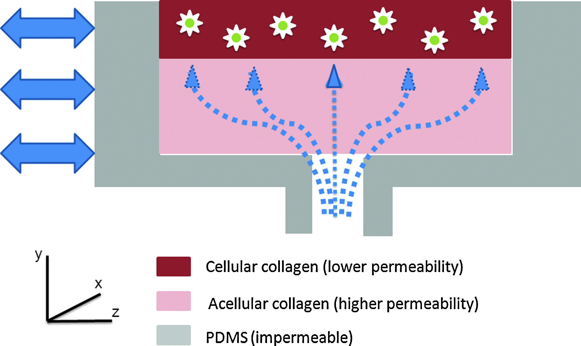
Schematic of one well of the flow–strain apparatus: a layer of porous, acellular collagen allows for distribution of flow (dotted lines) in the z-x plane, before passing through the cell-seeded gel in the positive y direction. Cyclic tensile strain (solid arrows) is applied in the z direction. Color images available online at
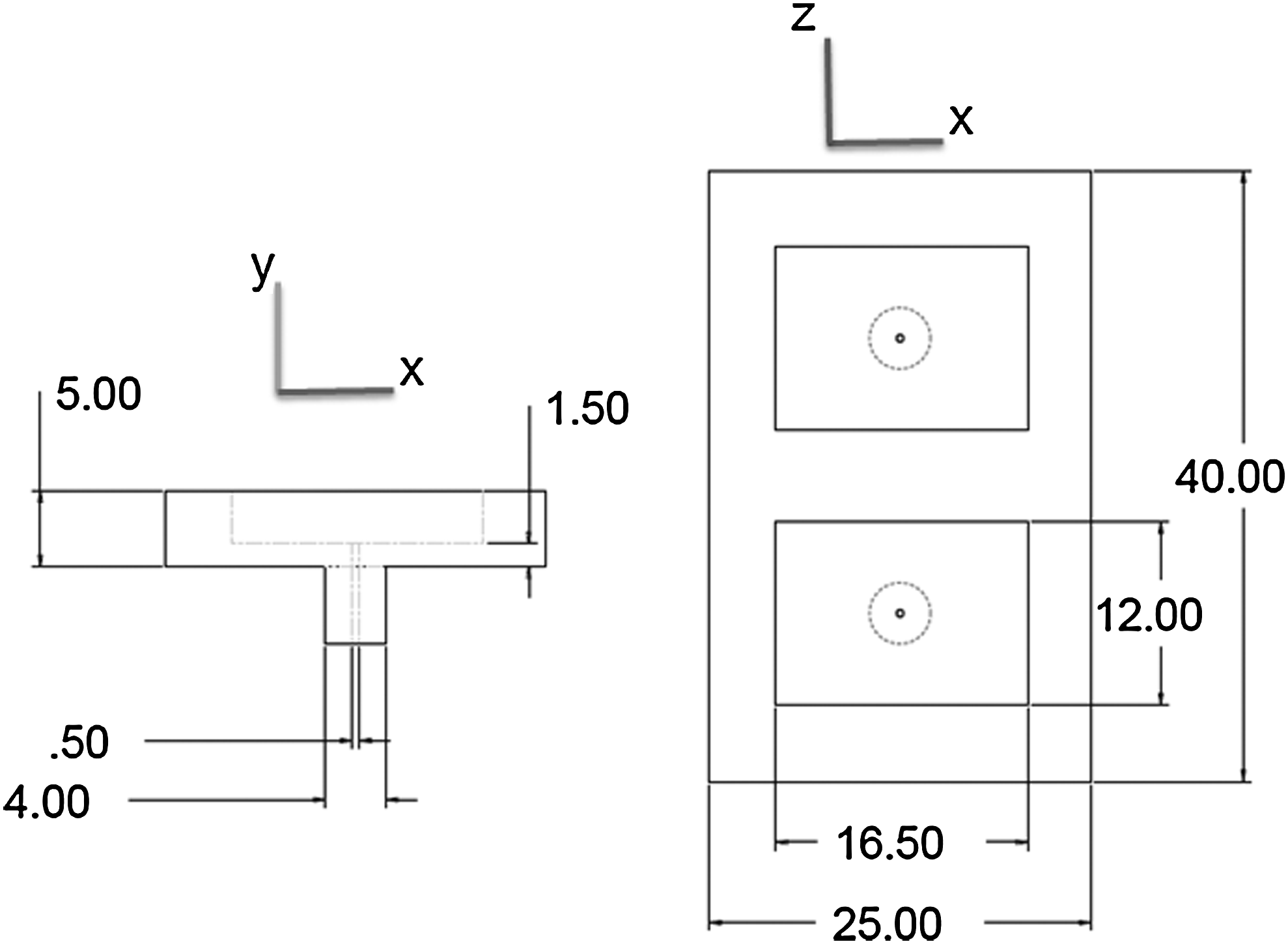
Schematic of polydimethylsiloxane (PDMS) wells (all dimensions in mm).
Fabrication and characterization of PDMS construct holder
The construct holder was made and prepared for use with collagen constructs by a multistep process shown schematically in Figure 3. PDMS base and curing reagent (Sylgard 184 Silicone Elastomer Kit; Dow Corning, Midland, MI) were combined in a 10:1 (wt/wt) ratio and were mixed thoroughly. The substrate mold was created using a primary Delrin template containing porous polyethylene blocks (Small Parts, Seattle, WA) to produce textured wells. The mold was sprayed with NoStick (Stoner, Quarryville, PA) to facilitate removal of the formed substrate (Fig. 3A). Inlet molds were inserted to create the inlet port to each well and the PDMS mixture was poured into the mold (Fig. 3B). The assembled and filled mold was baked at 150°C for 10 min and the cured PDMS substrates were removed from the mold. The inlet ports were then sealed with dowels and each well was filled with 10 N sulfuric acid for 90 min to etch the silicone surface and promote protein attachment (Fig. 3C). The wells were then thoroughly rinsed in deionized water and sterilized by an autoclave. Each well was filled with a solution of 20 μg/mL collagen type I dissolved in phosphate-buffered saline (PBS) and incubated at 4°C for 4–5 days to facilitate collagen deposition (Fig. 3D). In preparation for experiments, the dilute collagen solution was removed from the wells and the acellular and cell-seeded collagen gels were fabricated in the wells, as described in the following sections.
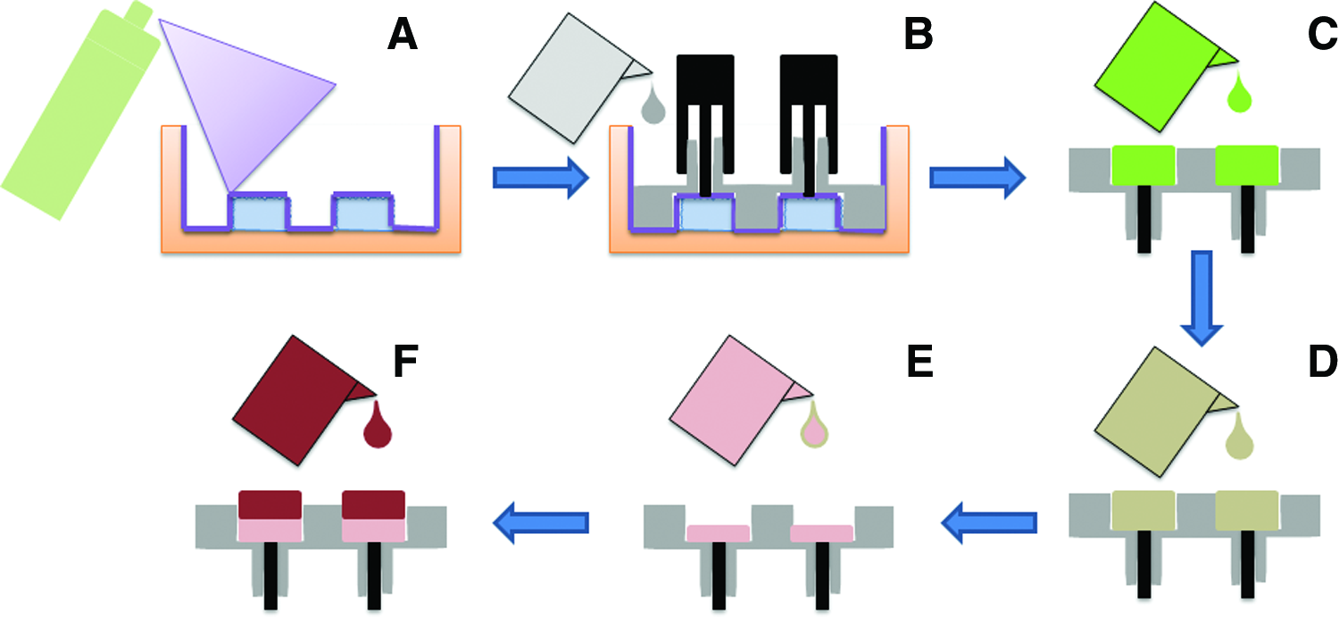
Fabrication and preparation of PDMS wells:
To examine the effects of acid etching on the PDMS well surface, samples were analyzed by scanning electron microscopy. A control sample was taken directly after the curing process. Samples were also taken after the acid etching and after the collagen coating steps. All samples were sputter coated with platinum–gold, and images were collected at two magnifications on a scanning electron microscope (FEI Company, Hillsboro, OR).
Finite element modeling
COMSOL Multiphysics version 4.0 (COMSOL Inc., Burlington, MA) was used to construct a finite element model of the PDMS substrate under 5% normal strain in the z direction. The software was used to render the geometry of the 3D substrate and create a quadrilateral mesh. The mesh size was determined by increasing node resolution until the computed strain distribution was unaffected by changing the resolution. The hydrogels were not included in the model because their elastic modulus is three orders of magnitude less than the PDMS,22,23 and hence do not affect the mechanics of the PDMS. The PDMS was modeled assuming infinitesimal strains and isotropy, so the compliance tensor, C, in the stress–strain governing equation can be fully described by the elastic modulus and Poisson's ratio.
where σ is the stress tensor, and u is the displacement tensor of the solid. The values of these parameters, E = 1.8 MPa and υ = 0.45, were taken from a previous study. 23
Cell isolation and culture
Cardiac fibroblasts were isolated from the ventricles of 2–3-day-old Sprague–Dawley rats using a previously described enzymatic digestion protocol. 24 Cardiac fibroblasts were chosen because of previous studies that demonstrate their sensitivity to mechanical stress.25,26 This procedure is approved by the Institutional Animal Use and Care Committee at the University of Michigan and is in compliance with the Guide for the Care and Use of Laboratory Animals published by the National Institutes of Health. Briefly, minced ventricles were digested in 0.125% trypsin and 0.15% pancreatin (Sigma-Aldrich, St. Louis, MO) at 37°C in consecutive 15-min steps. Fibroblasts were separated from myocytes in a preplating step, and cultured with M199 medium supplemented with 1% penicillin-streptavidin and L-glutamine and 10% fetal bovine serum. Cells were cultured for 1 week with medium changes every 2 days before use in experiments. The cells were then trypsinized and used for seeding in 3D collagen constructs.
Fabrication of 3D acellular and fibroblast-seeded collagen constructs
Three-dimensional protein hydrogels were fabricated using acid-solubilized bovine collagen type I (MP Biomedicals, Solon, OH) using previously described techniques. 22 For cell-seeded gels, cardiac fibroblasts were suspended in at a concentration of 5.0 × 10⁵ cells/mL in a cold solution of 2.0 mg/mL collagen and 10% fetal bovine serum in Dulbecco's modified Eagle's medium (Gibco Invitrogen, Carlsbad, CA). The pH of this suspension was adjusted to ∼7.4 by the addition of the appropriate amount of NaOH, and the temperature was raised to 37°C to initiation gelation of the collagen matrix. Acellular gels were made using the same technique without the addition of cells.
For the acellular collagen sublayer, 300 μL of acellular gel was poured into the PDMS wells and allowed to gel at 37°C in a humidified 5% CO2 incubator. After an hour of incubation, 700 μL of cellular gel was added on top of the set acellular gels, and again allowed to gel at 37°C in a humidified 5% CO2. Constructs in wells were kept in the incubator for 24 h before permeability testing or flow observation.
Application of strain and flow
The setup used to apply interstitial flow and mechanical strain to 3D constructs is shown in Figure 4. As shown in the schematic in the inset, fluid flow was applied through the inlet ports of the PDMS wells while strain was applied by stretching the entire PDMS substrate. The whole system was maintained at 37°C using an outer water bath. The PDMS substrate was held by nylon grips, one of which was affixed to the floorplate of the bath chamber, whereas the other was affixed to an axial mechanical actuator system and control software (Test Resources, Shakopee, MN). Interstitial flow was supplied by a syringe pump (KD Scientific, Holliston, MA) through tubes connected to the well inlet ports, which were fitted with pressure sensors (Freescale Semiconductor, Austin, TX).
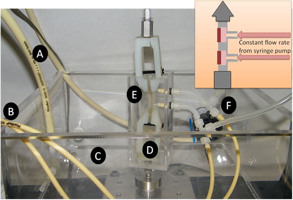
Assembled flow–strain apparatus:
This apparatus has the capability to apply strain and flow, either separately or in combination. For the experiments described here, the strain protocol was to apply 5% cyclic strain at 1 Hz, whereas interstitial flow was applied at 10 μL/min. The strain was kept below 5% to maintain the infinitesimal strain assumption used in the finite element modeling. The flow rate was chosen to match previous interstitial flow studies.7,8
Permeability testing
The testing setup provided a straightforward method of measuring permeability, since the syringe pump delivered a constant and known flow rate (Q), and the pressure sensors could measure the pressure upstream of the constructs. Assuming the downstream pressure was atmospheric and negligible pressure drop between the measuring point and the constructs (∼10 cm), the sensors gave the total pressure drop across the constructs (dP/dx). Because the dimensions of the constructs were confined by the PDMS wells, the area (A) was also known. Hence, permeability could be calculated using Darcy's equation for porous flow:
Flow observation
To assure the fluid flow distributed in the z-x plane in the acellular region before passing through the cell-seeded gel, photographic image-based flow observation was used. Erioglaucine (792.85 g/mol) was added to PBS in a 1:100 ratio (v/v) and supplied through the well inlet ports at 10 μL/min. The gels were then imaged at intervals up to ∼80 min under both static conditions and while being exposed to a 5% cyclic strain at 1 Hz.
Assessment of cell viability
Cell viability was assessed using the Live/Dead® assay kit (Invitrogen, Carlsbad, CA). The gels were removed from the PDMS substrates, and washed three times with PBS. The gels were then incubated at 37°C for 1 h in PBS containing both ethidium homodimer and calcein AM in concentrations recommended by the manufacturer (4 and 2 μM, respectively). After incubation, the gels were again washed three times in PBS and observed with an Olympus 500 confocal microscope at 10 × magnification.
Cell viability was assessed at multiple time points and testing conditions. All gels were incubated for 24 h in static conditions before being transferred to the testing setup until the 72 h time point. At 72 h, all gels were removed from the testing setup and either processed or returned to the incubator. For example, the gels for the 120 h time point were removed from the testing setup at 72 h and placed back in the incubator. Cell viability at 24 h after gel preparation, as well as at 72 and 120 h under static, no-flow conditions served as controls. Viability also was assessed after exposure to 10 μL/min fluid flow, 5% strain at 1 Hz, and combined flow and strain at these levels.
Results and Discussion
Adhesion of collagen constructs to PDMS wells
To apply simultaneous cyclic strain and defined fluid flow through the construct, it is necessary that the collagen matrix remains firmly attached to the walls of the PDMS well to prevent fluid leakage around the edges of the gel. Cardiac fibroblasts seeded in a 3D collagen matrix will remodel and compact the collagen fibers 22 and in the presence of uniaxial cyclic strain the cells will align the matrix in the direction of the strain. 27 These processes produce forces that can pull the collagen matrix away from the walls of the well, and therefore these cellular forces need to be overcome to maintain attachment of the gel to the PDMS.
Acid etching of the PDMS and subsequent coating with dilute collagen was used to promote construct adherence to the wells. In the absence of any treatment, hydrogels detached from the PDMS after 4–6 h. After etching the PDMS with 10 N sulfuric acid, gels stay attached for 2–3 days. When additionally coated with 20 μg/mL collagen type I after etching, the 3D gels remained attached to the PDMS for 14–18 days. To determine whether the etching produces surface changes to the PDMS that might be responsible for increased collagen adherence, scanning electron microscopy was used to analyze the microstructure of the surface. Figure 5 shows electron micrographs of untreated (Fig. 5A, B), acid-etched (Fig. 5C, D), as well as etched and coated PDMS surfaces (Fig. 5E, F). Untreated surfaces were essentially smooth with <1 μm surface features. After 90 min of etching with sulfuric acid, the PDMS displayed clearly larger surface features, in the order of 10 μm. After collagen coating, the surface once again exhibited a smooth appearance, presumably due to filling of the features with collagen matrix. While acid etching produced a much rougher surface topography, it is not known whether it also changed the surface chemistry or charge. The rougher surface provided improved gel adhesion, but subsequent collagen coating clearly had the greatest positive effect on collagen gel adherence.
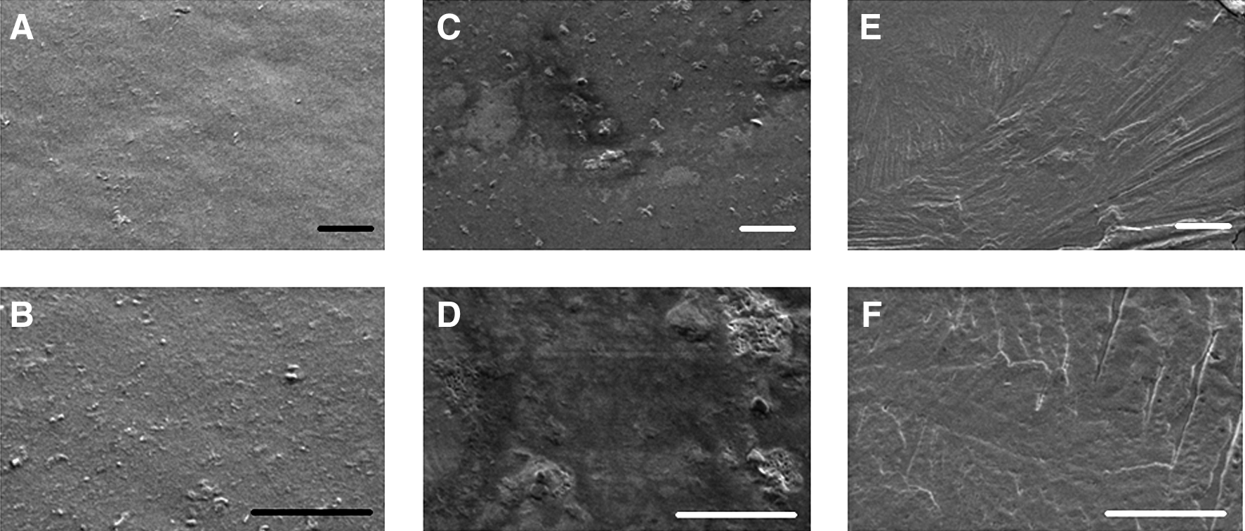
Scanning electron microscopy images of the PDMS surface.
Finite element model
A global uniaxial strain of 5% was applied to the apparatus based on the initial PDMS substrate dimensions. We performed finite element modeling to better characterize the strain field and to determine the actual magnitude of strain on the constructs within each of the wells. The results of this modeling are shown in Figure 6, and show that there are regional variations in the applied strain. Figure 6B shows the z component of the strain tensor (∂w/∂z) along a y-z slice through the midline of the deformed PDMS substrate. The model shows that the PDMS material between the wells is essentially unstrained in the z-direction, whereas the floor surfaces of the wells exhibit axial strains of slightly >5%. The strain distribution was relatively continuous on the surface of the well with the exception of the location of the fluid inlet.
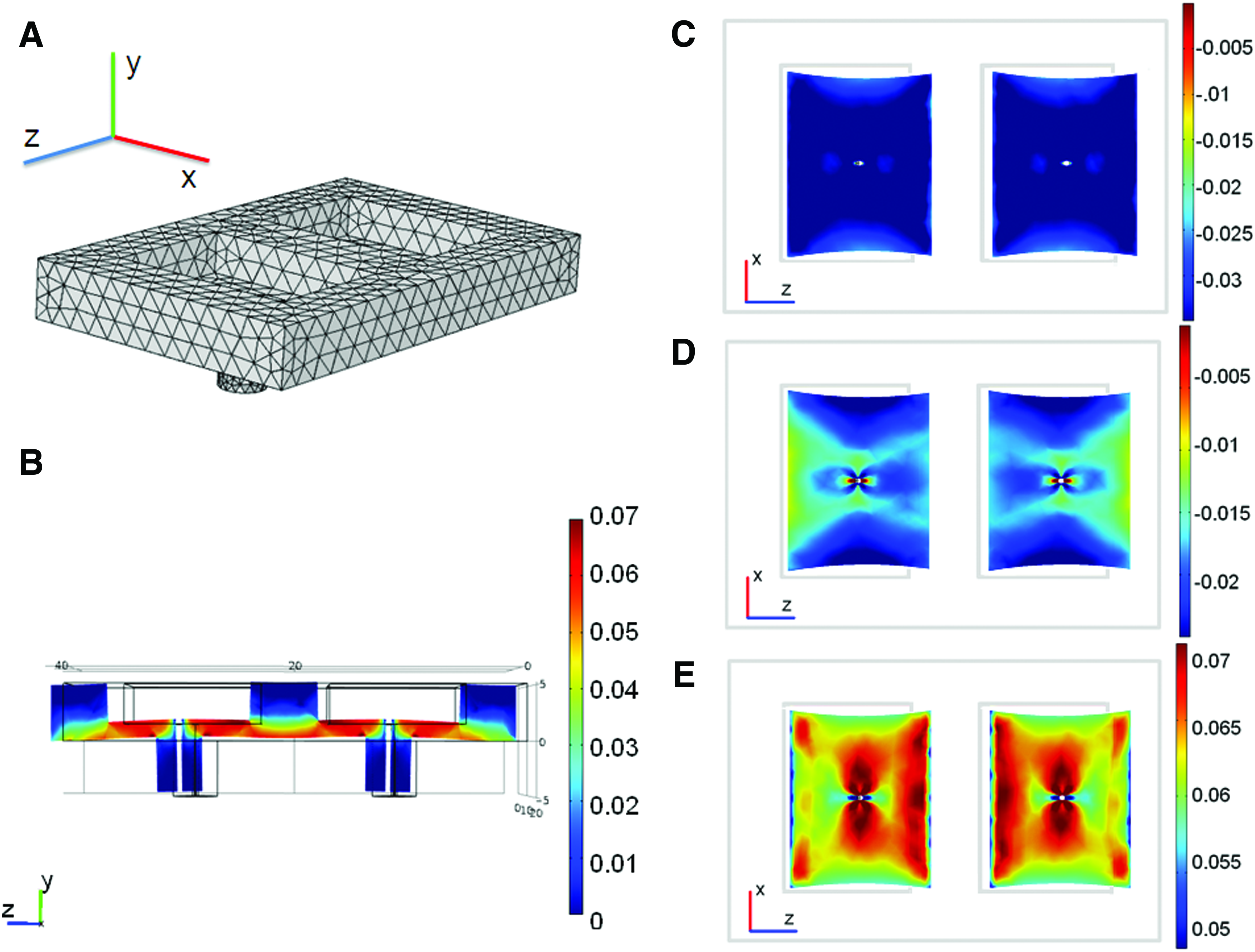
Finite element model.
Due to the relatively high Poisson's ratio of the PDMS (υ = 0.45), an axial strain of 5% in the z direction also produced deformation in the x and y directions. The bottom surfaces of the deformed wells are shown in Figure 6C–E, which show the x-, y-, and z-components of the strain tensor, that is, (∂u/∂x, ∂v/∂y, ∂w/∂z), respectively. The averages and standard deviations of the strain values for these surfaces were calculated for each well. The average strain in the x-direction on the surface was −0.029 ± 0.008 for both the wells, −0.018 ± 0.009 for both wells in the y direction, and 0.065 ± 0.014 for both wells in the z direction. Therefore, while there was slight compression (2%–3%) in the x and y directions, the tensile strain applied to the wells was ∼6.5%. These results validate that the primary component of strain was in the z direction, though the magnitude was slightly greater than the global applied strain. The local variation in the strain field that was observed suggests that this model is not appropriate for microscale analysis of the effects of strain. However, it is appropriate for tissue-level analysis since the wells experienced similar strains that were close to the applied strain magnitude.
Permeability of unseeded and cell-seeded collagen gel
The layer of acellular collagen was used to achieve a uniform flow distribution before entering the fibroblast-seeded construct. For this approach to work, the acellular collagen layer must have significantly higher permeability than the cell-seeded construct, creating a higher pressure drop in the y direction (see Fig. 1) and resulting in preferential flow in the z-x plane. Once the pressure has built sufficiently in the acellular region, the fluid will then flow in the y direction across the cell-seeded gel, in spite of its lower permeability. Because of the simple geometry and known boundary conditions of the PDMS apparatus, it could be used to determine the permeability of collagen constructs.
Figure 7 shows the results of the permeability testing for both acellular and cell-seeded constructs under both static and strained conditions. Acellular gels exhibited approximately fourfold higher permeability than fibroblast-seeded gels. In previous published studies, the permeability values of acellular collagen gels at concentrations ranging from 10 to 30 mg/mL were determined. 28 A curve fit of this data can be extrapolated to 2 mg/mL, resulting in a permeability value of ∼5.4 × 10⁻¹¹ m3s/kg, which falls within the error of the present measurement of acellular gels. Cell-seeded gels exhibited lower permeabilities, around 1.4 × 10⁻¹¹ m3s/kg. Both types of gels were constrained and attached to the PDMS wells, so that gel compaction was prevented in the z-x plane, but not in the y direction. Therefore, compaction of the gels in this direction could be the cause of the reduced permeability.

Gel permeability measurements: permeability was measured for both acellular and cell-seeded gels for both static and 5% tensile strained conditions. Error bars represent one standard deviation from the mean measurement.
There was no significant difference in the permeability of static gels and strained gels, whether they were acellular or fibroblast-seeded. This measurement is important because it confirms that 5% global stretch did not cause leakage of fluid around the constructs, which would have resulted in substantially increased fluid transport. These findings also have significance for computational modeling of the gel mechanics, since they indicate that permeability can be considered independent of strain for this type of construct. A previous study analyzed permeability of collagen constructs exposed to compressive strain in the same direction as the fluid flow, and showed permeability was affected by strain. 21 The present result shows that strain in the plane perpendicular to the direction of flow does not affect permeability.
Flow distribution in acellular support gel
To directly test whether flow was uniformly distributed in the acellular region before passing through the cell-seeded gel, PBS containing blue dye was injected through the inlet of the construct wells under both static and cyclically strained conditions. Images were taken perpendicular to the z-x plane as the flow entered the PDMS wells and spread within the acellular region. Figure 8 shows the time course of dye perfusion at a flow rate of 10 μL/min under static conditions. The dye perfuses essentially evenly out of the inlet port and distributes within the acellular gel over about 80 min. It was evident that flow did not pass through the cell-seeded gel in the y direction until fully distributing in the z-x plane. Figure 9 shows similar image data for cyclic straining to 5% at 1 Hz. In this case, the flow distributes uniformly in the x direction; however, in the z direction the fluid initially flows preferentially in the direction of the applied strain. To quantify this effect, the position of the leading edge of the flow in the positive z direction was compared to the position of the edge in the negative z direction, using the inlet as the coordinate axis origin. Figure 10 shows the results of this analysis for both the static and strained gels. For the static gel, the ratio stays constant at approximately one, indicating uniform flow. For the strained gel, the flow is initially skewed in the positive z direction, though as time progresses and the acellular region fills, the ratio recovers to approximately one. This result indicates that although strain does affect the fluid flow profile, the flow first distributes in the z-x plane before passing through the cell-seeded construct for both static and strained conditions.

Flow observation for a static gel: these images depict the x-y plane of the layered acellular and cellular gels, as 10 μL/min of colored phosphate-buffered saline is injected into the PDMS wells. The blue dot near the center of the gel indicates the location of the fluid inlet. Color images available online at

Flow distribution for a cyclically strained gel. The blue arrow indicates the direction of strain, and again the location of the fluid inlet is visible. Color images available online at
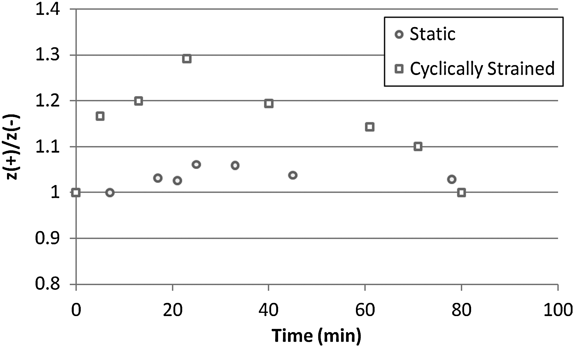
Quantification of flow observation: this plot indicates how the flow distribution in the cycling gel is skewed in the direction of strain (positive z direction) compared to the distribution in a static gel.
Cell viability in constructs under strain and flow
In order for the apparatus to be useful for studying cell responses to strain and flow stimuli, cell viability must be maintained in the 3D collagen construct. Figure 11 shows cell viability data for different time points, with and without strain and flow. At the 24 h time point, immediately before constructs are mounted in the strain/flow apparatus, cell viability was high (above ∼85%). When constructs were maintained in the PDMS wells in the absence of flow and strain, viability remained very high at both the 72 h and the 120 h time points. After stimulation by either flow, or strain, or a combination of flow and strain for 48 h (i.e., 72 h after initial creation of the construct), the viability in all constructs also remained very high (generally over 80%–90%). These data suggest that cells can be maintained in 3D collagen constructs in PDMS wells and that application of flow and/or strain does not compromise cell viability. This result is important for the use of this flow–strain system for the examination of cell function in 3D hydrogels over time.
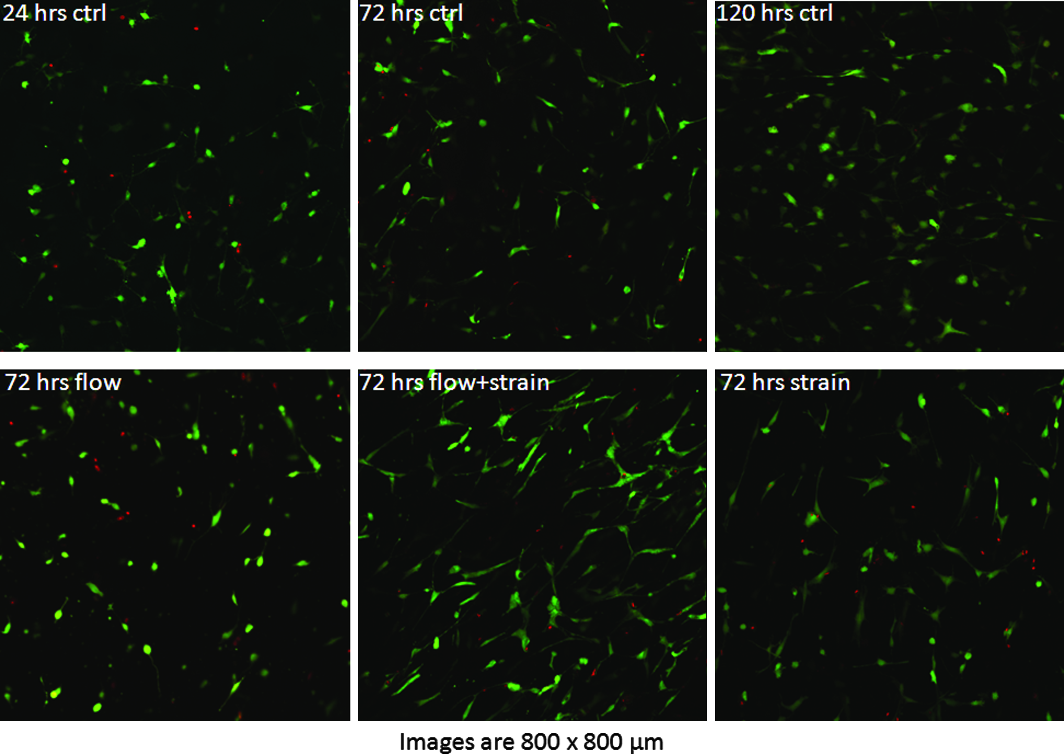
Cell viability for different testing configurations. Live cells enzymatically convert calcein AM to fluorescent calcein, while ethidium homodimer is able to penetrate the nuclei of dead cells and bind to nucleic acid, increasing its fluorescence emission by 40 ×. The images show a similar ratio of live to dead cells for all testing configurations and time points. All times are expressed in terms of hours after creation of the gels. All gels were incubated under static conditions for 24 h, and then exposed to either fluid flow, strain, a combination of both, or static conditions (control). Color images available online at
Conclusions
The results of this study validate the use of the described apparatus to apply simultaneous fluid flow and cyclic strain to cell-seeded hydrogels. The design is based on previously described interstitial flow bioreactors, with the key addition of applying simultaneous cyclic strain. The flexible PDMS substrate allowed for strain application and the surface could be modified to retain gel adherence over the duration of the experiment (120 h). As determined by finite element modeling, the main component of the applied strain was in the axial direction though the strain applied to each of the 3D constructs was slightly higher than the global strain. The results of the permeability and flow observation experiments directly validated the approach of using an acellular gel upstream of the cell-seeded gel to distribute the fluid flow evenly across the seeded construct. Imaging and viability studies confirmed that cells survived in the 3D protein hydrogel, both under static as well as strained and fluid flow conditions.
The ability to apply simultaneous interstitial flow and cyclic strain has relevance to the study of in vivo microenvironments. The type of simple bioreactor system described here can be used to model tissues such as the myocardium, which experiences interstitial fluid flow from perfusion through the extracellular matrix as well as cyclic strain from the systole–diastole cycle of the heart. In addition, it may have utility in a variety of other tissue systems in which both flow and strain are important modulators of cell function.
Footnotes
Acknowledgments
This work was supported in part by the Microfluidics in Biomedical Sciences Training Program at the University of Michigan, sponsored by the National Institute of Biomedical Imaging and Bioengineering.
Disclosure Statement
No competing financial interests exist.