
Abstract
Scaffold visualization is challenging yet essential to the success of various tissue engineering applications. The aim of this study was to explore the potential of X-ray diffraction enhanced imaging (DEI) as a novel method for the visualization of low density engineered scaffolds in soft tissue. Imaging of the scaffolds made from poly(
Introduction
X-ray microcomputed tomography (μCT) techniques, which are nondestructive and noninvasive, are becoming increasingly important for 3D visualization of scaffolds and engineered tissues in recent years. μCT can produce 3D image information to reveal the microstructure of scaffolds and regenerative tissues with specimen sizes from a few millimeters to 100 μm in size and provide nominal resolutions from 5 to 100 μm. 11 Quantitative architectural parameters of scaffolds, such as porosity, pore size, and pore wall thicknesses, can be extracted from μCT tomographic images.12,13 The new tissue growth and neovascularisation in scaffolds can also be visualized through 3D models reconstructed from the μCT data.14,15 Further, the noninvasive aspects allow this technique to be used to monitor new tissue regrowth in vivo in a time-lapsed fashion. 16 Although μCT techniques have been widely applied in bone tissue engineering, there have been few applications of μCT to soft tissue (e.g., nerve, vascular, and liver) engineering. The main obstacle is the low X-ray attenuation contrast of low-density scaffolds and soft tissues. Another issue is the high ionizing radiation dose absorbed by engineered tissue samples during μCT imaging, which has potential effects on cellular activity during the repair process.17,18
X-ray phase-contrast imaging techniques differ from conventional attenuation contrast-based X-ray imaging techniques because they instead rely on the refraction properties of object structure; they thus promise better contrast at lower doses. 19 Coupling synchrotron radiation (SR)-based X-ray sources to phase-contrast imaging techniques offer advantages such as better image quality, high photon flux, the possibility for monochromatization with a brilliance several orders of magnitude higher than those of a standard X-ray source, high spatial resolution (<1 μm), and a better signal-to-noise ratio.20,21 In-line phase-contrast imaging (in-line PCI) based on interference is one of the X-ray phase-contrast imaging techniques 22 that has been successfully applied in the visualization studies in soft tissue engineering, including imaging of articular cartilage, 23 sciatic nerves, 24 and microvascular networks in bioceramic scaffolds. 25 In-line PCI is restricted to either thin objects or high X-ray imaging energies. 26 Diffraction enhanced imaging (DEI), another important X-ray phase-contrast imaging technique, does not depend on interferometric techniques and works well with thick samples. Due to the use of a crystal analyzer with high angular resolution, DEI is sensitive to the boundary between tissues and/or biomaterials with different refractive indices.27–29 It is possible to obtain scatter-free absorption contrast images or refraction images rather than a mixture of the two. DEI has been used in visualization of soft tissues, for example, in the characterization of breast cancer30,31 and cochlea. 32 To date, little work has been reported in tissue engineering to take the aforementioned advantages of DEI to the visualization of soft engineered scaffolds and tissues.
This article presents a study on the use of X-ray DEI to visualize low-density scaffolds in soft tissue engineering. Specifically, poly(
Materials and Methods
PLLA (mw, 105) was purchased from DURECT Corporation. Chitosan (28191), Span 80, glutaraldehyde, and other chemicals were purchased from Sigma-Aldrich. Acetic acid was diluted at 2% (wt/vol) concentration in distilled water as the stock solution.
PLLA/chitosan scaffold fabrication
Chitosan microspheres
Chitosan microspheres (CMs) were prepared using an emulsion-ionic crosslinking method. Briefly, chitosan (200 mg) was dissolved in 2% (wt/vol) acetic acid solution (10 mL). Liquid paraffin (50 mL) containing 1% (vol/vol) Span 80 emulsifier was used as an oil phase. The water phase was dispersed into the oil phase using a magnetic stirrer (1000 rpm) for 30 min to form a water-in-oil (W/O) emulsion. Next, glutaraldehyde as a crosslinking agent was slowly dropped into the W/O emulsion to solidify the chitosan droplets. The crosslinking reaction was allowed to proceed for 2 h. Once separated by means of centrifugation, the CMs were washed two times with isopropyl alcohol, two times with ethanol, four times with distilled water under centrifugation of 3000 rpm, and eventually lyophilized.
Grid pattern PLLA/chitosan scaffolds
Tissue-engineered scaffolds were fabricated using a dispensing-based fabrication system. 33 Briefly, 20% (wt/vol) PLLA was dissolved into chloroform and then mixed with 40% (wt/vol) CMs. After the CMs were uniformly mixed into PLLA solution, the mixture obtained was then loaded into the dispenser for scaffold fabrication. Under pressurized air, the mixture was extruded onto a glass substrate layer by layer, forming scaffolds with a 3D grid-pattern structure. The scaffolds became solid once the chloroform volatilized.
Sample preparation
Tissue sample preparation
A Sprague Dawley rat was deeply anesthetized and perfused transcardially with 0.1 M phosphate-buffered saline (PBS), pH 7.4, followed by 4% paraformaldehyde in 0.1 M PBS. Muscle tissues were then removed from the rat for X-ray imaging and histological experiments. Animals were cared for according to the protocols of the Committee on Animal Care of the University of Saskatchewan (Animal Use Protocol #20080046).
Scaffold sample preparation for X-ray imaging
PLLA/chitosan scaffolds were trimmed to a thickness of 0.5 mm. One of the scaffolds was selected an then sequentially put into different media for imaging. Specifically, the scaffold was (1) placed in air hereafter referred to as “A-scaffold,” and directly exposed in X-rays for imaging; (2) embedded into rat muscle tissue with a total thickness of both scaffold and tissues of 5 mm (“M-scaffold”); then (3) removed from the rat tissue and immersed into water in containers with different inner thickness for imaging (“W-scaffold”), and the inner thickness of containers was 1, 4, and 5 cm, respectively.
Laboratory X-ray imaging
The laboratory X-ray images of the samples were captured using a SkyScan 1172 system (Skyscan) with an image pixel size of 3.5 μm. The X-ray source was set at an energy level of 60 kVp. To enable comparison with the synchrotron X-ray images, experiments were performed only in projection mode with a single magnified image of the sample at the X-ray energy recorded.
SR-based X-ray imaging
SR X-ray imaging experiments were carried out on the BioMedical Imaging and Therapy (BMIT) beamline at the Canadian Light Source (CLS), Saskatoon, Canada.
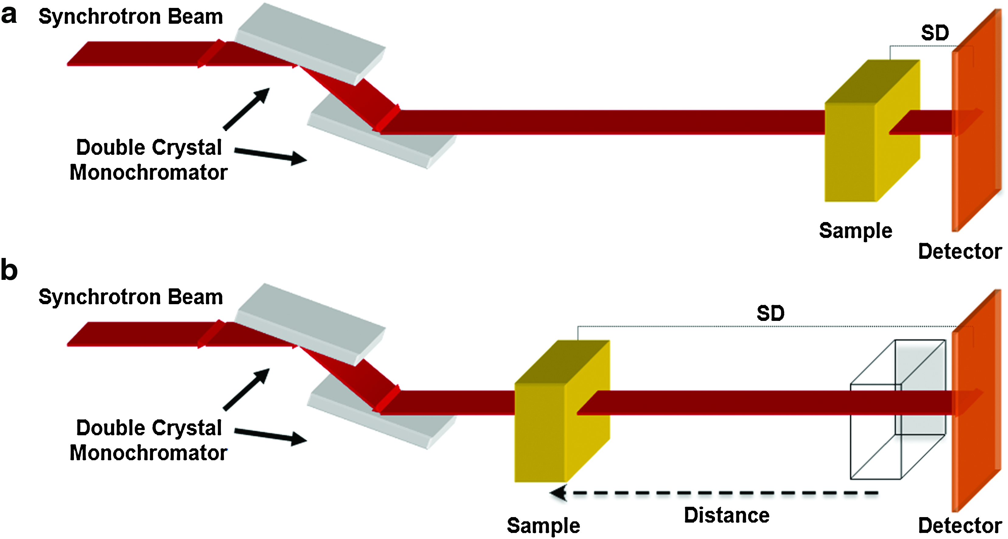
SR-radiography and in-line PCI
Figure 1 is a schematic of the SR-radiography and in-line PCI setups. The samples were exposed to the synchrotron generated X-rays at different stage positions (Sample to Detector distance [SD]) to obtain absorption contrast (SD=2 cm) and phase-contrast (SD=72 cm) projection images. Three different X-ray photon energy energies (15, 20, and 25 KeV) were applied in the imaging processes.
Systems for synchrotron radiation (SR)-based
Diffraction enhanced imaging
Figure 2 is a schematic of the DEI setup. The white synchrotron beam was monochromatized by an Si (220) double-crystal monochromator. The crystal analyzer was arranged behind the samples and installed on an axis that can rotate to be tuned to any position of its rocking curve. The DEI images were recorded by means of a beam monitor AA-40 (HAMAMATSU) coupled to a charge-coupled device camera (HAMAMATSU C9300, 4000×2672 pixels) with an effective pixel size of approximately 4 μm. The measured resolution of this configuration of the DEI system exceeds 18 μm (20% contrast using a 28 line pair per mm resolution test phantom). The X-ray photon energy was set at 20 KeV.
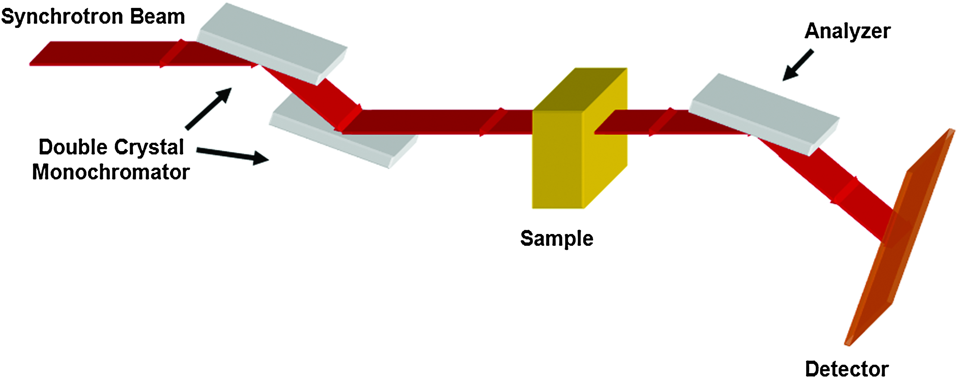
Synchrotron radiation-based diffraction enhanced imaging (DEI) setup. Color images available online at
For each sample, three projection images were acquired: one at the peak of the rocking curve and one on each side of the rocking curve at the half maximum point. The image captured at the low angle side of the analyzer crystal is referred to as the low angle image (L), and the image captured at the high angle side of the analyzer crystal is referred to as the high angle image (H). At each position, three images (a sample image, a flat image, and a dark image) were captured for image normalization. All DEI images obtained were then processed using MATLAB 7.7 software (Mathworks, Inc.) to form the refraction angle images using the following equation (1).
27
where ΔθZ is the refraction contrast in the plane of diffraction; θH and θL are symmetrical angles on both sides of the rocking curve; IH and IL are the intensities in the analyzer at θH and θL, respectively; R(θ) is the rocking curve of the analyzer; and (dR/dθ)(θH) and (dR/dθ)(θL) are the slopes of the rocking curves at θH and θL, respectively. For images obtained at the 50% reflectivity points, R(θL)=R(θH) and dR/dθ (θH)=−dR/dθ (θL).
Histology and SEM
For histological assessment, scaffolds were embedded in 15×10 mm slices of rat muscle tissue that were postfixed using 4% paraformaldehyde in 0.1 M PBS overnight and then cryoprotected overnight in 20% sucrose at 4°C. The muscle tissues were flash frozen using an acetone and dry ice slurry. The tissues were sectioned on a cryostat (Micron, Zeiss) to 6 μm and stained using a standard hematoxylin & eosin protocol.
The morphology of the scaffolds was investigated by SEM (EVO60, Zeiss) with an accelerator voltage of 20 kV, in which samples were coated with gold using a Denton Vacuum Desk IV coater.
Results
PLLA/chitosan scaffolds
The PLLA/chitosan scaffolds were fabricated by using dispensing rapid prototyping method. Images of the scaffold were taken by using a camera and SEM are shown in Figure 3. The SEM image shows morphological features of the scaffold, where the rough surface of the strands in the scaffold is due to the presence of CMs (with a concentration of 66.7%). The scaffold shown in Figure 3a was used in all X-ray imaging experiments to eliminate potential sample variablility (e.g., scaffold density) in the comparison of different X-ray imaging techniques.

Images of the PLLA/chitosan scaffold from
Imaging the scaffold in air
The scaffold in air or A-scaffold was visualized using laboratory-based radiography, and SR-radiography, in-line PCI, and DEI techniques (Fig. 4). The profile of the scaffold was visualized using both laboratory-based (Fig. 4a) and SR-radiography (Fig. 4b) but with poor image details. The principle of these radiography techniques is based on the absorption contrast of imaged objects. As such, the low density of the scaffold results in inadequate image contrast. In the DEI process, the refraction image (Fig. 4d), which was obtained from both the low- and high-angle images, shows the profile of the scaffold more clearly than the radiographs (Fig. 4a, b) and the in-line PCI image (Fig. 4c), especially, at the edges of the scaffold strands. The refraction contrast image represents the spatial gradient of the refractive index (horizontal in Fig. 4d), enhancing and highlighting edge appearance, contour interfaces of polymers, and environments. Further, the refraction image reveals detailed information about the CMs mixed in the strands of the scaffold, which also caused the scatter rejected by the analyzer.
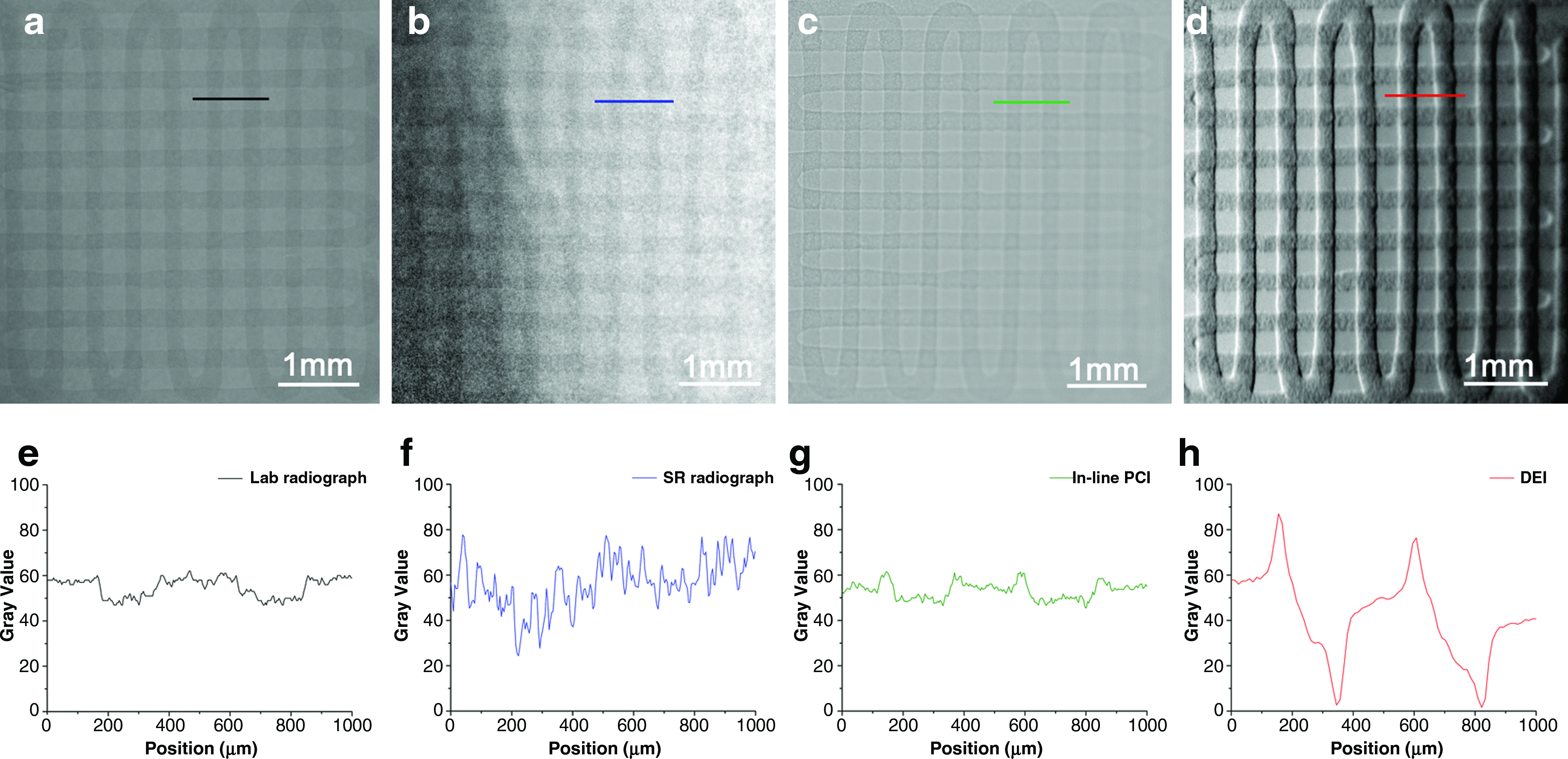
Comparison of the PLLA/chitosan scaffold images with laboratory-based radiography, synchrotron radiation-based radiography, in-line PCI, and DEI using the same sample at a similar magnification.
Figure 4e–h shows the gray value changes at the same location of the scaffold in the laboratory and SR radiographs, in-line PCI image, and DEI refraction image, respectively. The grayscale contrast in the refraction image is a factor of two higher than in the radiographs and in-line PCI image. Both radiography and in-line PCI are affected by X-ray scatter, whereas DEI can reject X-ray scatter and produce a pure refraction image. Compared to in-line PCI, DEI is able to show stronger contrast in images and has a higher sensitivity to object edges. Notably, DEI is sensitive to gradients in the projected density along a single direction. This effect accounts for the weaker contrast variations from the horizontal strands as compared to those from vertical ones in Figure 4d. However, the tissue scaffolds are 3D arrays of strands so that no matter the orientation of the scaffold, there will be refraction contrast. The scaffold material also has scatter contrast (sometimes called extinction contrast). The contrast accounts for the other modalities. This type of contrast is isotropic and does not depend on the orientation of the strands. During image processing, most analyses for qualitative and quantitative detail, such as scaffold porosity, pore size, surface area-to-volume ratio, and interconnectivity, are based on image grayscale contrast. As such, appropriate grayscale contrast makes image analysis more accurate.
Imaging the scaffold in muscle tissue
After being embedded in the muscle tissue, the sample or M-scaffold was imaged using laboratory-based radiography, in-line PCI, and DEI, respectively (Fig. 5). Using conventional laboratory-based radiography at 60 Kvp, the scaffold tissue is not visible and the profile of the muscle tissue is unclear (Fig. 5a). The contrast of the radiograph is based on X-ray attenuation; however, because the attenuation of muscle tissue and the polymer scaffold are close due to their similar densities, distinguishing them using radiography techniques is difficult. Using in-line PCI at 20 KeV, the profile of the muscle tissue can be distinguished and the scaffold is faintly visible (Fig. 5b). However, the DEI image clearly shows the M-scaffold and has high contrast (Fig. 5c). The contrast of DEI images is based on the refraction and scattering properties of the object. Further, many spots along the scaffold strands can be identified in the DEI image (Fig. 5c) due to the presence of the CMs, consistent with the A-scaffold DEI image (Fig. 4d). The CMs within the strands cause X-ray refraction that is captured by the detector throughout the analyzer. Although the scaffold was embedded into muscle tissues, the DEI image of the M-scaffold provides the most detailed image information of the A-scaffold DEI image (Fig. 4d).
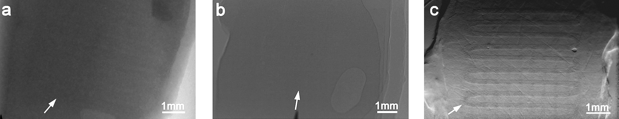
X-ray images of the PLLA/chitosan scaffold embedded in rat muscle tissue (M-scaffold):
The DEI images of the M-scaffold provide detailed information on the scaffold structure as well as the profile of the muscle tissue. In Figure 5c, many short lines can be observed in the muscle tissue area. To identify these features, we conducted a histological analysis on the same muscle tissue after the X-ray imaging was conducted and the scaffold was removed. Figure 6a shows a typical image of the muscle tissue at the same location as the DEI image. The light microscopy image shows the muscle tissues are separated into many small pieces by some white edges (Fig. 6a arrow) that have a similar distribution to the short lines in the DEI image (Fig. 5c). By magnifying the edge area in the muscle tissue, the histological image (Fig. 6b) indicates that the connective tissues pack the muscle cells into bundles of muscle fibers, with boundary interfaces formed between them. The presence of this detail indicates that the DEI technique is sensitive to refraction differences inside the soft tissues and is thus able to provide structural information about the soft tissues, particularly edges inside the tissue microstructure. The comparison of the DEI image to the histological analysis suggests that the structure discrepancy in soft tissues can be reflected in DEI images.

Light microscopy images:
Effect of sample thickness for DEI
To investigate the effect of soft tissue thickness on the visualization of low density scaffolds, the PLLA/chitosan scaffold was immersed into water (W-scaffold) and imaged using DEI at a photon energy of 20 KeV. Water was used as a substitute for soft tissue in this investigation; imaging results for scaffolds in water are comparable to scaffolds in soft tissue and water has a similar density and X-ray mass attenuation coefficient as soft tissue. The results illustrated that, the scaffold is clearly distinguishable in the DEI refraction images at sample thicknesses of 1 and 4 cm (Fig. 7a, b) but not 5 cm (not shown). Figure 7c, d shows the gray value changes at the same location of the scaffold marked in Figure 7a, b, respectively. The grayscale contrast in both DEI images is similar, with the grayscale contrast of the 4-cm-thick W-scaffold not significantly less than the 1-cm-thick W-scaffold. These results suggest the DEI system at 20 KeV is capable of distinguishing the PLLA/chitosan scaffold in soft tissues with thickness up to approximately 4 cm.
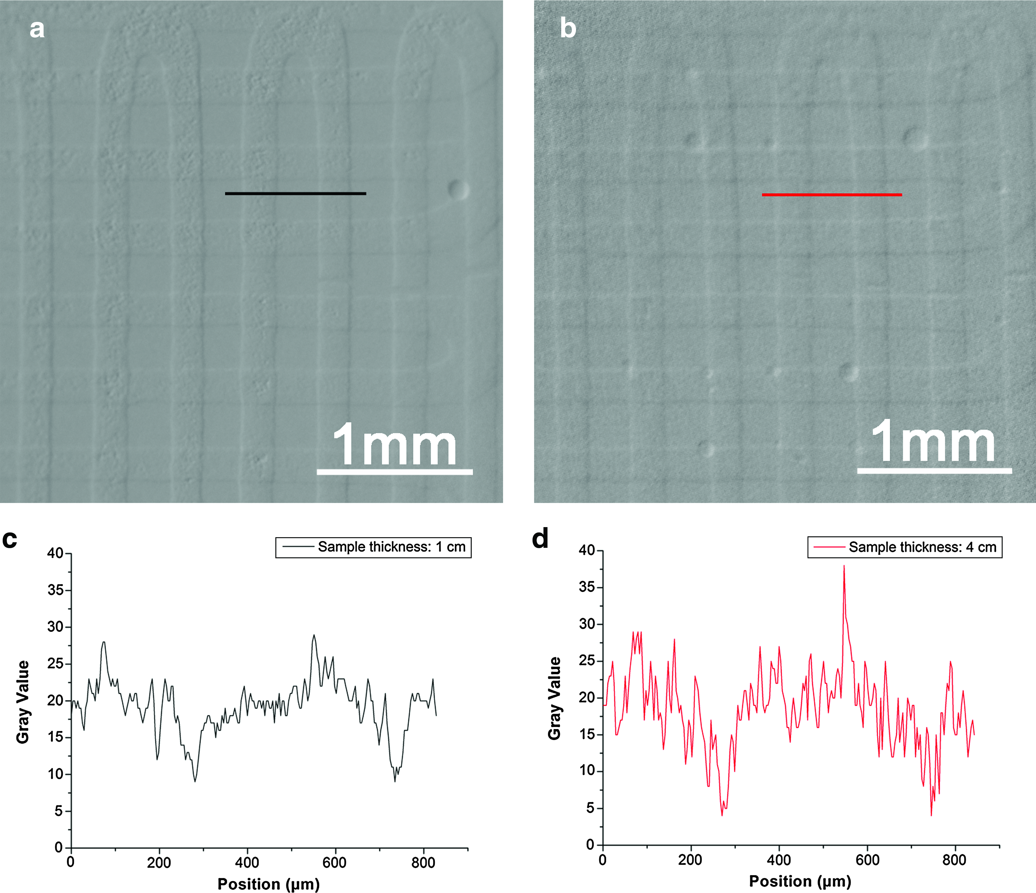
DEI images of the PLLA/chitosan scaffold in water (W-scaffold) at a photon energy of 20 KeV and total sample thicknesses of
Radiation dose and radiograph quality
The surface-absorbed dose rates experienced by the scaffolds at different average photon energies during X-ray imaging were evaluated according to the following equation (2)
34
:
where
As the X-ray photon energies increase, the dose rates of the sample decreased (Table 1); for example, photon energy increase of approximately 60% (from 15 to 25 KeV) results in a dose rate reduced of approximately 60% (from 2.16 to 0.86 mGy/s).
The image contrast of the A-scaffold in the SR-radiographs at different photon energies is shown in Figure 8d–f. The images become blurry (Fig. 8a–c) and image contrast substantially declines as the photon energy is increased; for example, the scaffold in Figure 8a is clearly visible at a photon energy of 15 KeV but is barely visible at a photon energy of 25 KeV. The results indicate that better X-ray attenuation contrast of samples can be obtained using radiography at lower photon energies but the sample is consequently exposed to higher dose rates.
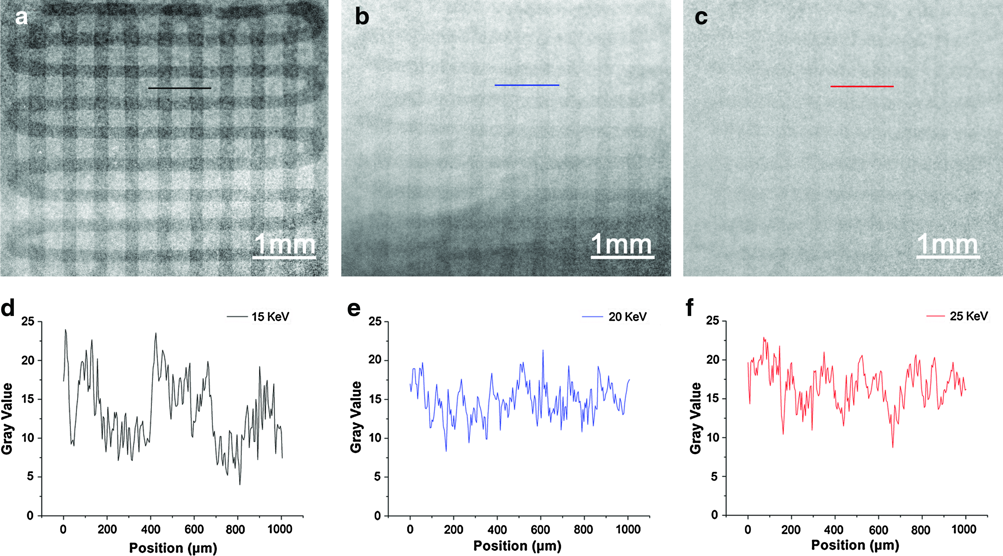
SR-radiographs and corresponding image contrast of the scaffold in air (A-scaffold) at different photon energies with the sample to detector distance of 2 cm:
Discussion
The present study illustrates, for the first time, the possibilities of DEI for the visualization of low density tissue scaffolds. Specifically, we visualized the PLLA/chitosan scaffold in both air environment and muscle tissue using different X-ray imaging techniques including laboratory- and SR-radiography, in-line PCI, and DEI. For comparison, all the images were captured from the same scaffold sample. The DEI technique can visualize low density scaffolds in muscle tissue better than any of the other techniques considered here. Moreover, DEI has the potential to be fully noninvasive and nondestructive for both in vitro and in vivo applications in soft tissue engineering research. This would allow low density scaffolds to remain intact for additional assessments as well as facilitate the monitoring of either degradation behaviour or new tissue ingrowth after implantation, which is especially relevant for preclinical trial applications. Inspired by the promising results from the present study and the fact that the integration of DEI and CT techniques (i.e., DEI-CT) can provide 3D visualization of tissue samples, such as breast tissue, 35 we believe that DEI-CT can be applied to realize the 3D visualization of engineered scaffolds and newly-generated tissues in vivo.
Scatter is a problem in conventional X-ray imaging where it is common for over half of the X-rays that reach the detector to be of scatter origin. Thus, antiscatter grids are used to reject some of this scatter, which improves image contrast. In DEI technique, howerver, the use of an analyzer can reject off-angle and off-energy scattered X-rays primarily from Compton scattering. As such, this technique is almost scatter free. 27 This effect of extreme scatter rejection has two key advantages. First, this effect can be used to enhance the contrast from small structural features, such as lung alveoli and fur, from rejection of ultra-small X-ray scattering. 28 Second, another important effect is that the increased scatter from thick objects becomes almost completely irrelevant, which allows them to be imaged at no loss of contrast due to scatter (see Fig. 7). This is part of the reason why DEI is so successful at imaging large thick objects at higher X-ray energies. 36 In this study, the ability to image the PLLA/chitosan scaffold in soft tissue using DEI at 20 KeV was limited to sample thicknesses up to approximately 4 cm; the reason is that a log-linear relationship between the transmitted photon flux and the sample thickness prevented further penetration. 37 Higher X-ray energy DEI systems with higher photon fluxes can visualize thicker tissue samples; for example, breast tissue samples with thickness of 12 cm have been clearly visualized at 60 KeV. 38 We plan to revisit the issue of sample thickness when higher X-ray energy becomes available at the BMIT beamline in the future.
Degradation of resolution due to the DEI system was not observed in this work. The resolution of the DEI system is determined by source size, the pixel size of the detector, and the distances between the source, object, and detector; also, there will be a small (approximately 1 μm) contribution in the diffraction plane due to beam penetration into the analyzer crystal. The current resolution could meet the requirements of the tissue level and scaffold degradation studies in situ and possibly in vivo. Considering the potential variety of samples and wide range of sizes relevant for soft tissue engineering applications, higher resolution imaging systems might be helpful for smaller fields of view, whereas low resolution systems with a large field of view may be more useful for in vivo applications.
During X-ray imaging, the dose absorbed by the sample is lower at higher photon energy levels. Photoelectric absorption in the sample contributes to the main part of the total attenuation at low photon energy levels (and a high dose received by the sample), whereas Compton scatter in the sample plays the leading role in the processes at high photon energy levels. 39 In conventional radiography, absorption contrast is directly related to the dose received by the sample. Better image contrast means more absorbed X-rays and more dose to the sample at lower photon energy levels. 28 In tissue engineering applications, high dose X-ray imaging processes will change the material properties of the imaged scaffolds and the biological properties of the imaged tissues. The harmful effects of ionizing radiation present in conventional X-ray imaging are a notable challenge to applying these techniques to tissue engineering, especially for in vivo visualization. 18 In DEI, the sample absorbs the same dose as conventional radiography at the same X-ray energy, but additional image contrast is generated from X-ray refraction. Thus, compared with radiographs at the same energy level, DEI images of scaffolds embedded in muscle tissue demonstrate higher contrast. Furthermore, DEI can be optimally applied at higher X-ray energies and lower doses in visualization applications. 27 When 2D X-ray imaging techniques are extended to 3D applications, the combination of DEI and tomography techniques will cause order-of-magnitude reductions in radiation dose and offers great promise for the visualization and characterization of scaffolds and regenerative tissues in living animals.
Conclusions
Visualization of low density materials using conventional radiography is a challenging task due to weak X-ray attenuation. Rising to this challenge, we visualized low density PLLA/chitosan scaffolds by DEI and compared our results to conventional radiography and in-line PCI. When visualized in air, the DEI images of the scaffolds were much clearer compared to radiographs and in-line PCI images. DEI was also demonstrated to have the capacity to provide enhanced image contrast that could reveal detailed morphology of low density scaffolds. After embedding the scaffold into rat muscle tissue, the images obtained shows DEI can provide higher quality visualization of scaffolds as compared to both radiography and in-line PCI. The DEI images show not only the structure of the scaffold but also the microstructural features of the muscle tissue. In addition, the DEI technique accomplishes good imaging performance with low radiation doses at high energy levels. Overall, DEI technique has great potential for visualization applications in soft tissue engineering, in particular the real-time observation of engineered tissues in living animals.
Footnotes
Acknowledgments
Research described in this article was performed at the CLS, which is supported by the Natural Sciences and Engineering Research Council of Canada, the National Research Council Canada, the Canadian Institutes of Health Research, the Province of Saskatchewan, Western Economic Diversification Canada, and the University of Saskatchewan. Financial support from the Saskatchewan Health Research Foundation (SHRF), Canada Foundation for Innovation (CFI), and the CIHR Training grant in Health Research Using Synchrotron Techniques (CIHR-THRUST) is acknowledged. Special thanks to George Belev and Brian Bewer for technical assistance in the preparation of the DEI system.
Disclosure Statement
No competing financial interests exist.