
Abstract
Recently, in situ tissue engineering has emerged as a new approach to obtain autologous, living replacement tissues with off-the-shelf availability. The method is based on the use of an instructive biodegradable scaffold that is capable of repopulation with host cells in situ and subsequent tissue formation. This approach imposes high demands on scaffold properties. For cardiovascular grafts, the repopulation with endogenous cells from the circulation is further hypothesized to be influenced by the hemodynamic environment of the scaffold. To systematically study the effect of scaffold properties on the response of circulating cells, we aimed to develop a mesofluidics-based in vitro test platform that enables on-stage investigation of the interaction of circulating cells with three-dimensional (3D) synthetic scaffolds under physiologic hemodynamic conditions. The test platform consists of a custom-developed cross-flow chamber that houses small-scale 3D scaffolds. The cross-flow chamber is incorporated into a flow-loop to drive a cell suspension along the scaffold with physiological wall shear stress and perfusion pressure. The fluidics system is validated numerically and experimentally using a computational fluid dynamics model and real-time microbead tracing studies, demonstrating a fully developed flow profile with a homogeneous shear stress distribution over the scaffold. Wall shear stresses and pressure can be controlled independently, well within the target physiological range (0–8 Pa and 0–100 mmHg, respectively). Bench-top evaluation is performed using electrospun poly(ɛ-caprolactone) scaffolds with varying fiber diameter, exposed to a suspension of human peripheral blood mononuclear cells in pulsatile flow for 72 h. Cell adhesion and infiltration are monitored using time-lapsed confocal laser scanning microscopy. In conclusion, we have successfully developed a mesofluidics platform to study cell–scaffold interactions under hemodynamic conditions in vitro. This platform not only enables us to systematically screen and develop potential scaffolds for future in situ cardiovascular tissue engineering approaches, but also acts as a tool to further elucidate processes as observed in vivo.
Introduction
In addition to self-endothelialization, the scaffold should guide the ECM production of host cells to overtake the role of the biodegradable scaffold as load-bearing structure. Circulating progenitor cells are capable of sufficient matrix production when provided with the correct stimuli in vitro,17,18 although the optimal subpopulation is still focus of debate.19–23 Thus, repopulation of the scaffold with endogenous circulating (progenitor) cells is a key element in the process of in situ tissue regeneration. This repopulation should not be limited to cell capture at the surface, but should extend to proper influx, migration, and distribution of the appropriate cell populations throughout the entire scaffold.
We hypothesize that the hemodynamic environment plays an important role in the innate response of circulating cells to a synthetic scaffold. Both heart valves and arteries continuously experience substantial dynamic loads, such as cyclic strains, transmural pressures, and shear stresses. In the adult human, wall shear stresses are estimated to be in the range of 0.1–8 Pa on the aortic valve leaflet24,25 and 1.5 Pa for small-caliber arteries. 26 The transmural pressure difference over the aortic valve leaflet rises up to 80 mmHg during diastole, while the physiological arterial pressure lies in the range of 100 mmHg. To study the effects of hemodynamics, the individual and combined stimuli can be simulated in vitro. Parallel-plate flow chambers are widely used as a tool to study the effect of shear stress on two-dimensional (2D) cell cultures.27,28 Shear stress has been described as a determining factor in the efficacy of adhesion of EPCs, as well as smooth muscle cells and endothelial cells (ECs) on functionalized surfaces in microfluidic devices.28–31 Furthermore, it has been shown that fluid shear stress modulates EC invasion in 3D collagen matrices.32,33 de Mel et al. demonstrated spontaneous endothelialization in a statically preseeded nanocomposite vessel model at physiological shear stress and pressure conditions in vitro. 34 With respect to cell infiltration in a 3D scaffold, the pressure difference over the scaffold has a determining influence on cell infiltration and the resulting perfusion flow through the scaffold can be used as a seeding method for homogeneous cell distribution throughout the scaffold.35–38
Clearly, the response of circulating cells evoked by a 3D synthetic scaffold in vivo is dependent on a number of factors. Local biochemical and biomechanical influences play a role, as well as structural scaffold properties, such as porosity, architecture, and surface modifications. To systematically investigate the effect of scaffold properties on circulating cell activation, capture, and subsequent tissue development, we aimed to develop a mesofluidics-based in vitro test platform that enables on-stage investigation of the cell–scaffold interactions under physiologic hemodynamic conditions. Here, we describe the development of a custom-made fluidics platform that allows for testing of small-scale, simple geometry 3D scaffolds under hemodynamic conditions in a high-throughput and reproducible fashion.
Materials and Methods
Model system
Cross-flow chamber design
A cross-flow chamber was developed to subject 3D scaffolds to a cell suspension in flow at predefined wall shear stresses, while allowing for perfusion of cells through the scaffold under influence of an applied pressure difference (Fig. 1). The chamber consists of two polyether ether ketone (PEEK) discs and a stainless steel gasket containing the fluidic channel (Fig. 1A, B; chambers produced by BEMO BV, Oisterwijk, The Netherlands). The top disc houses 3D rectangular scaffolds (15×10 mm), with a variable thickness up to a maximum of 1 mm. The channel on top of the scaffold allows for perfusion flow. A highly porous stainless steel mesh restricts deformation of the scaffold in z-direction, without affecting transmural pressure over the sample. The bottom disc consists of a coverglass (Ø 32 mm, thickness 0.13 mm; VWR, Westchester, PA) in a PEEK housing, which can be mounted onto the stage of a standard inverted microscope table. In between both discs, the interchangeable gasket provides the actual fluidic channel, with channel dimensions of 28 mm in length, 7 mm in width, and 300 μm in height (h; see Fig. 1C). The chamber is fitted with two silicon O-rings to prevent leakage, and in- and outflow channels are equipped with polypropylene barbed fittings (Cole-Parmer, Vernon Hills, IL).

Three-dimensional (3D) drawings of the cross-flow chamber.
Computational design and validation
To define the wall shear stress as generated on the scaffold surface in the cross-flow chamber, the wall shear stress is related to the applied flow rate. The steady-state flow in the fluidic channel is described by Poiseuille flow between two infinitely wide parallel plates. Assuming culture medium as a Newtonian fluid and steady-state flow conditions, the wall shear stress τw (Pa) is calculated as a function of the applied flow rate Q (m3·s−1), according to:
with μ (Pa·s) representing the dynamic viscosity, and w (m) and h (m) representing the width and height of the channel, respectively.
39
The width/height ratio of the channel is taken into account to ensure a homogeneous wall shear stress with minimal influence of boundary effects in the region of interest (i.e., w/h>20).
40
This is only valid for a fully developed flow profile and the corresponding entrance length Lent is estimated as a function of the Reynolds number Re
41
:
with ρ the fluid density (kg·m3).
Numerical validation of the flow profile and wall shear stress distribution, for both steady-state and pulsatile flow conditions, was performed with a computational fluid dynamics model in COMSOL Multiphysics software (COMSOL BV, Zoetermeer, The Netherlands). The fluidic channel was modeled in three dimensions, with tetrahedral mesh elements, including the in- and outlet channels to assess the development of the flow profile. Permeability of the scaffold was not taken into account. For steady-state conditions, a constant normal inflow velocity of 0.42 ms−1 (corresponding to a volumetric flow rate of 10 mL·min−1) was prescribed as the boundary condition at the inlet. For pulsatile flow, a normal inflow velocity was prescribed by a sinusoidal waveform with an average velocity of 0.21 ms−1 and amplitude of 0.21 ms−1 at a frequency of 1 Hz (corresponding to a sinusoidal pulsatile volumetric flow rate between 0 and 10 mL·min−1 at 1 Hz). At the output, an initial zero pressure boundary condition was defined and for all other walls a no-slip condition was prescribed. The model was solved for the Navier-Stokes equation using a time-dependent solver, and the velocity profiles and shear stress distribution at the scaffold surface were analyzed.
Flow-loop
The cross-flow chamber is incorporated into a flow-loop to control the fluid flow and pressure inside the chamber (Fig. 2). Flow rate and pressure are controlled by two modified pressure pumps with a working range of −200 to +200 mbar (corresponding to −150 to +150 mmHg, Air Pressure Pump; ibidi GmbH, Martinsried, Germany). The flow is driven by a positive pressure generated by the first pump, connected to a Fluidic Unit (ibidi GmbH) that contains the cell suspension. In synchrony, a second, modified Fluidic Unit actively controls the transmural pressure difference over the scaffold sample by periodically imposing a negative pressure in the top chamber, delivered by the second pump. Pulsatility of the flow is controlled via the pinch valve of Fluidic Unit 2 (v2; Fig. 2) on both inlet tubes. In this way, the absolute pressure difference over the scaffold can be controlled independently of the flow rate. For long-term experiments, the fluidic volume in Fluidic Unit 2 is pumped back into Fluidic Unit 1 via a bypass tube. Fluidic Unit 1 can run continuously by periodically switching check valve 1 (v1; Fig. 2). Pumps and Fluidic Units are controlled by a LabVIEW software package (developed by ibidi GmbH). Four check valves (Qosina, Edgewood, NY) are incorporated to maintain proper direction of the flow. The pressure is measured in both the top and bottom channels by pressure domes (P10EZ; BD Medical Systems, Franklin Lakes, NJ), connected to a signal amplifier (Peekel, Rotterdam, The Netherlands). A clamp-on ultrasonic flow probe (2PXL; Transonic Systems, Inc., Ithaca, NY) in combination with a signal amplifier (TS410; Transonic Systems, Inc.) is used to monitor the flow rate in the system. Data are collected via a multi-IO-card using LabVIEW software (National Instruments, Austin, TX). In effect, the system can generate either laminar flow, with constant shear stress at the scaffold surface and constant transmural pressure, or a pulsatile flow, with a cyclic transmural pressure difference. Furthermore, the system can be used in a single-pass or recirculating fashion depending on the desired experimental conditions. The Fluidic Units soak up environmental air to maintain stable incubator conditions inside the reservoirs and to ensure gas exchange at the fluid–air interphase.
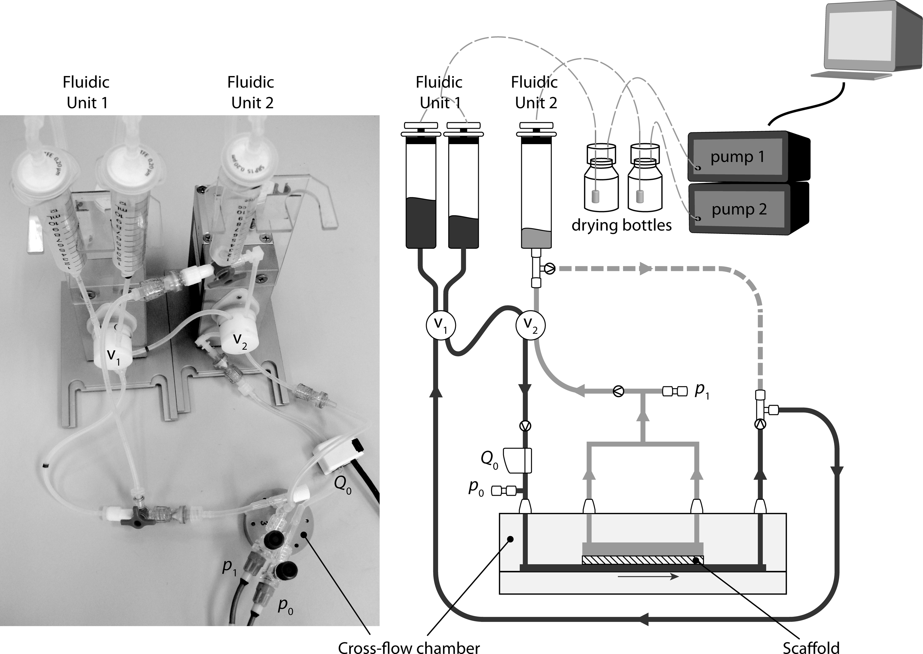
Picture (left) and schematic representation of the flow-loop (right) with the main components as indicated. The cross-flow chamber and the Fluidic Units are placed inside an incubator to maintain stable conditions of 37°C and 5% CO2. The pumps and drying bottles, as well as the signal amplifiers and computer system for data collection, are situated outside the incubator.
The performance of the flow-loop was assessed in terms of achievable pressures and flow rates in the cross-flow chamber. The theoretical pressure limits were determined by calculating the pressure loss due to friction and resistances in the flow-loop (i.e., tubing and connectors), according to:
with friction coefficient λ=64/Re(−) and resistance coefficient ζ (−), ρ the fluid density (kg·m3), L the tubing length (m), D the inner diameter tubing (m), and ū the average fluid velocity (ms−1).
Bench-top evaluation
Scaffold preparation
For bench-top testing of the system, poly(ɛ-caprolactone) (PCL; density ρPCL=1.15 g/cm3; Purasorb; Purac Biochem, Gorinchem, The Netherlands) scaffolds were produced by electrospinning. For this, the polymer was dissolved in chloroform (puriss, stabilized with ethanol; Sigma-Aldrich, St. Louis, MO) at 20% (w/w), and driven through a nozzle at high voltage (15 kV) toward a grounded rotating cylindrical copper target at 15 cm distance. To reduce the fiber diameter, pyridium formiate (PF) was added to the solutions at 10% (w/w) with respect to the total polymer content. PF was formed by mixing stoichiometric equivalents of pyridine (≥98%; Sigma-Aldrich) and formic acid (≥96%; Sigma-Aldrich). Scaffolds were kept under vacuum overnight to remove any remnants of the solvent. Scaffold quality, fiber diameter, and average interfiber distances in the x-y plane were determined with scanning electron microscopy (Quanta 600F; Fei, Hillsboro, OR). Rectangular samples (15×10 mm) were punched out of the scaffold sheet to be placed in the flow chamber. Thickness of the scaffolds was measured using optical profilometry (PLμ2300; Sensofar-Tech, Terrassa, Spain). Scaffold porosity ɛ (%) was determined according to equation (6):
with the bulk polymer density ρPCL (g/cm3) and the density of the electrospun scaffolds ρ0 (g/cm3). The latter was determined gravimetrically from the weight and thickness of mesh samples over a defined area.
Scaffolds were sterilized by UV exposure (30 min/side), hydrated in a graded ethanol series, and rinsed three times with phosphate-buffered saline (PBS).
Microbead tracing
Microbead tracing studies were performed to validate the steady-state flow profile in the system in correlation to the numerical predictions. Polystyrene fluorescent microbeads (FluoSpheres, Ø 10 μm, yellow-green 505/515; Molecular Probes, Eugene, OR) were suspended in PBS at a concentration of 1.5×10⁵ beads/mL. The microbead suspension was then driven through the cross-flow chamber at various constant flow rates (0–40 mL·min−1) in a single-pass fashion. Prior to each run, the microbead suspension was mixed by vortexing to ensure a homogeneous distribution of the beads. Flowing microbeads at the scaffold surface were visualized in real-time using a high-speed camera (50–200 frames/s; IDT MotionPro M5, Tallahassee, FL) connected to an inverted fluorescent microscope (Axiovert 200M; Carl Zeiss, Thornwood, NY).
Cell experiments
For proof-of-principle, a time-lapse experiment was performed to study the effect of scaffold architecture on cell infiltration. For this, two different electrospun scaffolds were used, either with an open-pore or a dense structure. The sterilized electrospun PCL scaffolds were incubated overnight in the culture medium to allow for protein adsorption to the scaffold surface. A neutral culture medium of RPMI 1640 (Gibco, Grand Island, NY) was used, supplemented with 10% fetal bovine serum (Greiner Bio-One GmbH, Frickenhausen, Germany) and 1% penicillin/streptomycin (Lonza, Basel, Switzerland). Human peripheral blood mononuclear cells (hPBMCs) were used as a representative cell source, naturally circulating in the human blood. The hPBMCs were isolated from fresh buffy coats from healthy donors (Sanquin Blood Supply Foundation, Nijmegen, The Netherlands) by density gradient centrifuging (Ficoll-Paque PREMIUM; GE Healthcare, Uppsala, Sweden). The isolated hPBMCs were fluorescently labeled by 30 min incubation with 10 μM CellTracker Green 5-chloromethylfluorescein diacetate (CTG; Invitrogen, Carlsbad, CA) directly before use, and resuspended in culture medium at a physiological concentration of 1.0×10⁶ cells/mL. For each run, a total of 10 mL of cell suspension was recirculated through the flow system for 72 h at a pulsatile flow rate at 1 Hz with a peak volumetric flow rate of 10 mL·min−1, corresponding to a peak shear stress of 1.6 Pa. Cell capture and infiltration was visualized using an inverted confocal laser scanning microscope (Axiovert 100M with LSM 510 scan head; Carl Zeiss). Z-stacks were recorded at various positions in the scaffolds, while inside the flow chamber, after 15 min and subsequently after 18, 24, 48, and 72 h of culture under flow.
Results
Model system
Cross-flow chamber
For culture medium, the dynamic viscosity was assumed to be constant at μ= 1×10⁻³ (Pa·s), while for whole blood calculations, shear thinning was taken into account using an empirical model relating the dynamic viscosity with the shear rate. 42 Predicted shear stresses are well within the range of physiological values for both small-diameter blood vessels as well as heart valves, as shown in Figure 3.24–26 Since the scaffold is positioned at x=6.5 mm >> Lent, we can assume a fully developed flow in the region of interest. This was confirmed by the time-dependent simulations, which show a fully developed parabolic flow profile at maximum flow rate (t=0.5 s) at the scaffold boundary at x=6.5 mm (Fig. 4A). Furthermore, the shear stress distribution in transverse direction is homogeneous over the full width of the scaffold with boundary effects falling outside the region of interest (Fig. 4B). As a result, the wall shear stress distribution in the region of interest is fully homogeneous (Fig. 4C). For the applied pulsatile flow conditions, the flow profile remains perfectly controllable in the laminar regime with a Reynolds number strictly below 90, and without any turbulence in the region of interest. This result can be extrapolated to higher flow rates in the target range (see Fig. 3), throughout the laminar regime.

Predicted wall shear stresses as a function of the applied flow rate. Culture medium is assumed to be a Newtonian fluid with constant viscosity. Whole blood is modeled as a non-Newtonian fluid with an empirical relation between shear stress and shear rate to account for shear thinning at high flow rates. The physiological target range (0–8 Pa) is indicated by the shaded area.

Results of the computational fluid dynamics simulations. The velocity profiles at the scaffold boundary (at x=6.5 mm) over the height
Flow-loop
Performance of the flow-loop was evaluated in terms of flow rate control and achievable pressures. Using equations 3–5, the theoretical pressure loss was calculated as a function of the applied flow rate. For this, the resistance coefficient of the loop was experimentally determined to be ζ=45. The maximum pressure loss due to tubing and connectors was calculated to be 27 mmHg at a maximum flow rate of 40 mL·min−1. Since the working range of the pumps is −150 to +150 mmHg, the effective working range of the complete flow-loop is well suitable to reach systemic pressures of 80–100 mmHg.
Validation experiments demonstrate that the system can generate a pulsatile pressure waveform below the scaffold (p0; see Fig. 2) at a frequency of ∼1 Hz (Fig. 5A). The resulting flow rate typically shows a block-shaped waveform and achievable shear stresses are well within the desired range for both small-diameter arteries and heart valves (Fig. 5B). Depending on the permeability of the scaffold, the transmural pressure difference (Δp=p0–p1) can be adjusted, independently of the flow rate, by imposing a negative pressure in the top chamber (p1; Fig. 5A). If desired, the top chamber can simply be closed to study solely the effect of a pulsatile flow on cell capture, without the effect of a transmural pressure gradient over the scaffold.
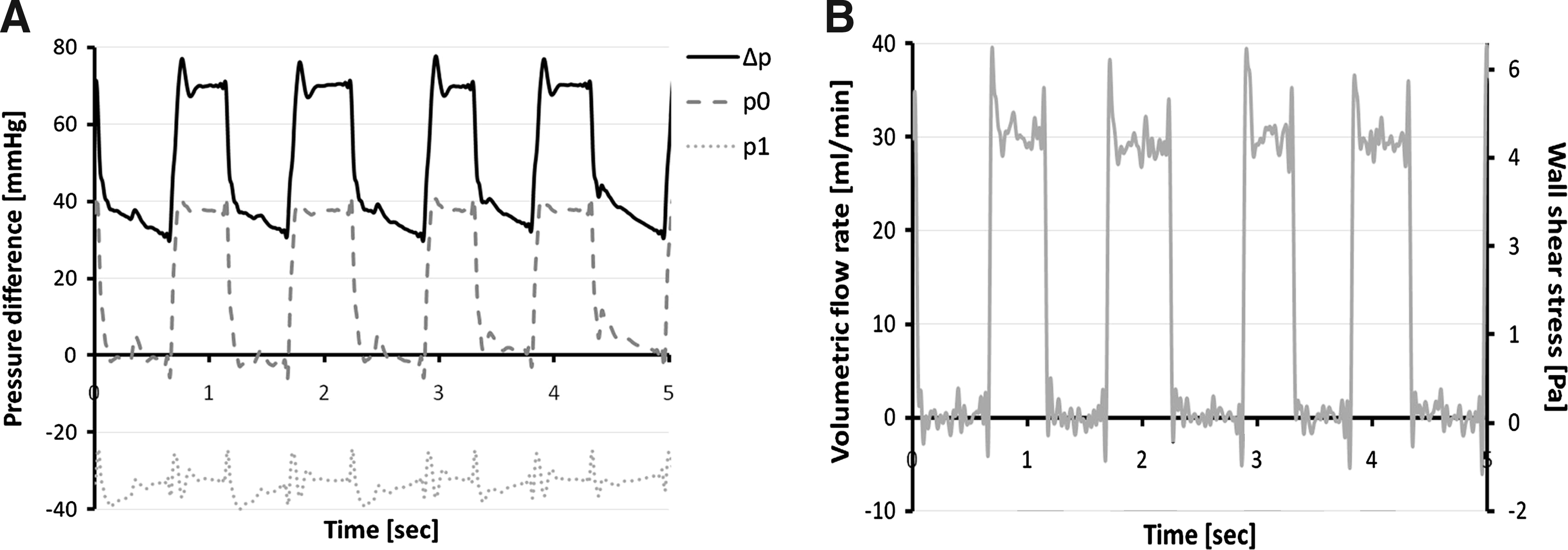
Representative example of measured waveforms for pressure
Bench-top evaluation
Ease of use
All parts of the cross-flow chamber can be autoclaved and are easily assembled in a sterile cabinet. By running the setup with 10 mL of PBS or medium prior to use, air bubbles present in the system after mounting are instantly removed via the fluid–air interphase in the Fluidic Units. Furthermore, gas exchange is achieved via this interphase since the pump soaks up environmental air (at incubator conditions) into the syringes through a 0.2 μm filter on the Fluidic Unit. A total volume of 10 mL is needed to operate the system, which minimizes the required amounts of cells. The Fluidic Units are designed to minimize cell agitation, which is of essence to prevent undesired early monocyte activation.
Scaffold preparation
Electrospinning resulted in homogenous porous scaffolds with random fiber orientation (Fig. 6). Two different scaffold sheets were created: an open-pore scaffold with an average fiber diameter of 10.2±0.4 μm and a more dense scaffold with an average fiber diameter of 0.66±0.2 μm. Thickness of the scaffolds was simply controlled by adjusting the total spinning time, resulting in an average thickness of 250 μm for both scaffolds. The porosity of the scaffolds is independent of the fiber diameter and was determined to be 89.9%±0.3% and 89.8%±0.6% for the open-pore and dense scaffold, respectively. The pore size, however, is directly correlated to the fiber diameter, with an average in-plane interfiber distance of 156.4±57.1 μm and 5.5±2.8 μm for the open-pore and dense scaffold, respectively.
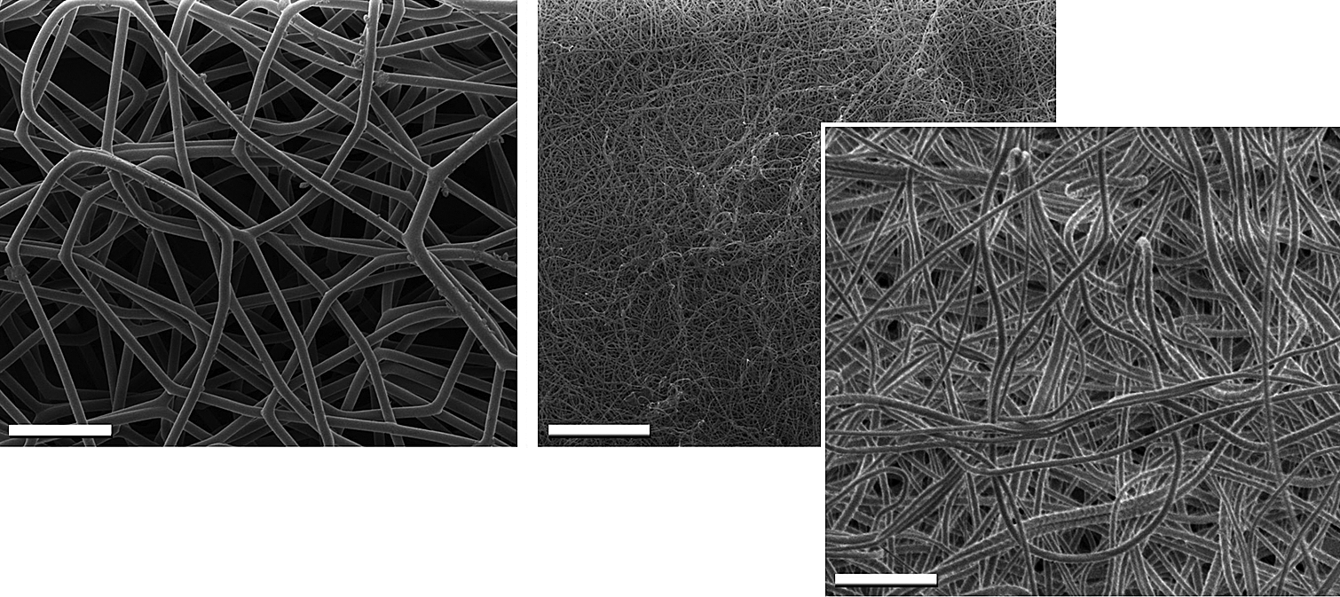
Scanning electron micrographs of the electrospun poly(ɛ-caprolactone) scaffolds with open-pore architecture (left) with an average fiber diameter of 10.2±0.4 μm and average interfiber distance in the xy-plane of 156.4±57.1 μm (scale bar=100 μm; magnification 500×), and a dense architecture (right) with an average fiber diameter of 0.66±0.2 μm and average interfiber distance of 5.5±2.8 μm (scale bar=100 μm; magnification 500×; inset: scale bar=10 μm; magnification 5000×).
Microbead tracing
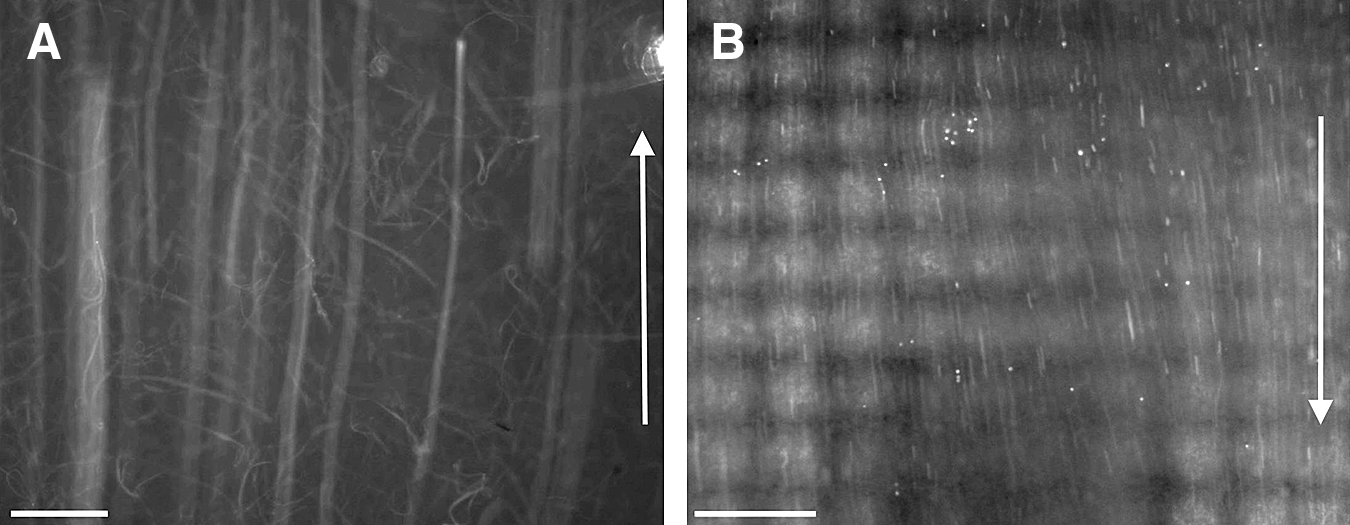
Results for the microbead tracing studies were consistent with the computational predictions. The fluorescent microbeads could be traced in real time. Streamline images demonstrate that the beads followed a straight trajectory without significant turbulence at the in- and outlet channels (Fig. 7A). No transverse motion of the beads was observed, indicating the absence of any unwanted transversal pressure gradient in the region of interest. Beads were passively entrapped in the scaffold during a single-pass flow cycle.
Cell infiltration
Cell isolation by density gradient centrifuging yielded on average 500×106 unselected hPBMCs from a single buffy coat (corresponding to a concentration of 1×10⁶ hPBMCs/mL of whole blood). The CTG-labeled hPBMCs were traceable in real time, revealing straight and uniform trajectories, similar to the results of the microbead tracing studies (Fig. 7B). Time-lapse confocal imaging demonstrates rapid cell infiltration into the open-pore scaffold within 15 min of flow, throughout the entire thickness of the scaffold (Fig. 8). Circulating cells accumulated homogeneously into the scaffold over time and remained viable up to the 96 h follow-up. Cells in the open-pore scaffold clearly adhere along the polymer fibers, unable to bridge the large interfiber distances (Fig. 8, inset). In contrast, cell capture into the dense scaffold remained limited to the scaffold surface with restricted cell infiltration. For these scaffolds, cells bridged the fibers of the dense polymer mesh, covering the scaffold surface over time (Fig. 8).
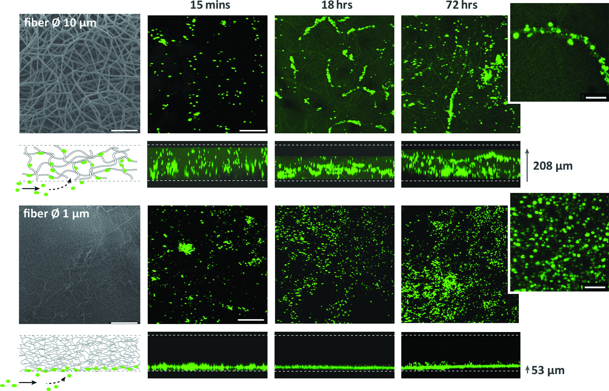
Cell infiltration into an open-pore (upper panel) versus dense scaffold (bottom panel) was compared using time-lapse confocal imaging. Scaffold orientation is clarified in the schematic illustration and the scanning electron micrograph (left; scale bar=200 μm). The corresponding confocal images show the distribution of viable cells in the xy-projections (scale bar=200 μm) and infiltration depth in the z-stacks at the various time points. For the open-pore scaffold, cell infiltration is homogeneous throughout the entire thickness for all time points, with average detectable infiltration depth of 208 μm in the z-stack. The total hPBMC population increases over time and cells adhere to the scaffold along the polymer fibers (see inset; scale bar=40 μm). For the dense scaffold, cell infiltration is hampered, with an average infiltration depth of 53 μm in the z-stack. hPBMCs accumulate over time, covering the scaffold surface (see inset; scale bar=40 μm).
Discussion
Repopulation of the scaffold with endogenous cells is pivotal in the process of in situ tissue engineering of heart valves and blood vessels. Circulating cells are exposed to specific hemodynamic conditions that play a crucial role in the activation, adhesion, and migration of such cells. In this study, we have developed an in vitro fluidics system that is capable of mimicking a range of physiologic hemodynamic conditions to study interactions between circulating cells and small-scale 3D scaffolds. Computational simulations reveal a fully developed flow profile in the custom cross-flow chamber, with homogeneous wall shear stress distribution on the entire scaffold surface. This was experimentally validated with real-time fluorescent microbead tracing experiments. Bench-top evaluation of the complete flow-loop demonstrates ease of use with minimal working volume of cell suspension needed. The double-pump configuration of the flow-loop allows for accurate and independent control of wall shear stresses and pressures in the physiological range for cardiovascular applications. In addition, the capture and infiltration of cells into the scaffold can be monitored in real-time or time-lapse fashion using confocal laser scanning microscopy. This feature, combined with viable fluorescent stainings, provides valuable temporal information on the cell population, cell number, and migration in the scaffold without the need to sacrifice the scaffold.
Looking into literature, flow chamber systems are no strangers in biomedical research and the effects of mechanical stimuli exerted by flow on multiple facets of cell behavior have been well recognized. With the upcoming microfluidics technologies, fluidic setups are increasingly scaled down, which offers several advantages over macro- or mesoscale systems. 39 In particular, individual parameters can be studied into great detail and with extremely high-throughput, such as the 2D studies by Plouffe et al. on the effect of shear stress on specific cell–substrate binding interactions.29–31 Furthermore, novel microfluidic setups are moving toward three dimensions,43–45 thereby increasing the potential applications of the technique. On a macroscopic scale, hydrostatic or -dynamic pressure gradients are extensively used in perfusion bioreactors, for example, in the field of cartilage tissue engineering, 38 but also as in vitro model systems to study living tissues, such as recently described for brain tissue by Rambani et al. 46 Chouinard et al. developed a stand-alone setup to subject high-density 3D cell cultures to pulsatile perfusion. 47 Anderson and Knothe Tate described an elegant dual-flow chamber system that houses membranes with well-defined shear stresses on both sides of the membrane. 48 However, to our knowledge, none of these systems combines well-defined wall shear stress with pulsatile pressure gradients in the physiological range, combined with real-time imaging for 3D scaffolds, as we demonstrate in this study.
Appropriate shear stress characterization is a prerequisite in the use of flow chambers, as underlined by Anderson et al. 27 Our simulations demonstrate a homogeneous wall shear stress distribution on the scaffold surface. However, it should be noted that this is only valid on a mesoscale, assuming a smooth and flat scaffold surface. The local shear stresses experienced by the cells will span a broad range in porous scaffolds, and particularly in fibrous electrospun scaffolds as used in this study. These local shear stresses will affect cell adhesion and are highly influenced by scaffold architecture and surface topology, 49 which should be considered in scaffold design. Additionally, scaffold architecture influences cell infiltration into and migration inside the scaffold and should be tuned for optimal cell infiltration under dynamic conditions.36,50,51 Our validation experiments demonstrate hampered cell infiltration for electrospun PCL scaffolds with fiber diameter in the <1 μm range, whereas cell infiltration is homogeneous throughout the entire thickness of the scaffold for fiber diameter in the 10 μm range. This is consistent with previously described data on the effect of fiber diameter on cell infiltration, 50 which underlines the potential of our developed setup as a screening platform for various scaffolds.
Clearly, the capture of cells into a scaffold is only the first step in a cascade of events that should lead to tissue regeneration. However, the initial response of circulating cells to the scaffold biomaterial is a primary determinant for long-term outcome, as recent studies have demonstrated.52,53 Long-term functionality of a scaffold requires knowledge and control of the differentiation and ECM production of recruited cells. The recirculating configuration of our model system allows the study of these processes, as well as their underlying mechanisms, under hemodynamic conditions for prolonged periods of time.
With respect to cell suspension used, the current feasibility study was limited to unselected hPBMCs and no cell characterization was performed as this was beyond the scope of this study. Although the PBMCs significantly contribute to the innate in vivo response, obviously this is a synergistic process involving multiple additional cell types.54,55 In this respect, additional cell types such as neutrophils and thrombocytes maybe added in the cell suspension. Furthermore, the viscosity of the medium can be adjusted to mimic blood mechanical properties, including shear thinning behavior. 56 Whole blood can be used in the fluidics system as an alternative to isolated cell suspensions, although the use of anticoagulants is required. To study the thrombogenic response of our scaffolds, dynamic platelet adhesion experiments or whole blood studies will be performed.
One of the major challenges to overcome for in situ cardiovascular tissue engineering is defining the target cell population. A heart valve replacement requires valve interstitial-like cells as end-type phenotype, while for blood vessels this is more a smooth muscle cell–like phenotype. This suggests that distinctly different differentiation pathways should take place or that the target cell population differs, depending on the target tissue. Is it necessary to actively recruit specific cell types to the scaffold or is (selective) cell capture from the bloodstream sufficient if the fate of captured cells is directed by an instructive scaffold? Specific circulating progenitor cells maybe targeted, such as CD34+ or CD133+ cells that are present in the blood in small fractions. However, it may prove difficult to capture specifically these cells in the presence of the innate foreign body response evoked by the scaffold in vivo. Another interesting approach would be to modulate this in vivo response toward a favorable wound healing response and in this way repopulate and remodel the scaffold over time. 53 The challenge of appropriate cell recruitment is a major focus of our ongoing work, with the developed fluidics system acting as a useful tool to study the processes involved and to systematically tune and optimize scaffold properties accordingly.
In conclusion, we have successfully developed an in vitro test platform to study the interactions between circulating cells and 3D synthetic scaffolds under hemodynamic conditions on the mesoscopic scale, allowing for future high-throughput analysis. This platform not only enables us to systematically screen and develop potential scaffolds for future in situ cardiovascular tissue engineering approaches, but also acts as a model system to further elucidate the various processes involved in the foreign body response evoked by the scaffold in vivo. When applied hand-in-hand with in vivo studies, this provides a powerful setup to synergistically advance toward successful in situ cardiovascular tissue engineering.
Footnotes
Acknowledgments
The authors would like to thank Rob van den Berg for his help in prototype development of the cross-flow chamber and Marc Simonet for his expert assistance in electrospinning of the scaffolds. The technical assistance of Ulf Rädler and Miro Krautvar (ibidi GmbH) in modifying the pump setups is gratefully acknowledged. This research forms part of the Project P1.01 iValve of the research program of the BioMedical Materials Institute, co-funded by the Dutch Ministry of Economic Affairs, Agriculture and Innovation. The financial contribution of the Nederlandse Hartstichting is gratefully acknowledged.
Disclosure Statement
No competing financial interests exist.