
Abstract
In this work we present a bioprinting technique that exploits the electrohydrodynamic process to obtain a jet of liquid alginate beads containing cells. A printer is used to microfabricate hydrogels block by block following a bottom-up approach. Alginate beads constitute the building blocks of the microfabricated structures. The beads are placed at predefined position on a target substrate made of calcium-enriched gelatin, where they crosslink upon contact without the need of further postprocessing. The printed sample can be easily removed from the substrate at physiological temperature. Three-dimensional printing is accomplished by the deposition of multiple layers of hydrogel. We have investigated the parameters influencing the process, the compatibility of the printing procedure with cells, and their survival after printing.
Introduction
B
There is an increasing interest in using cell-based bioinks so that cells can be placed at predefined positions. In fact this approach raises new possibilities for a wide range of applications. It could be possible, for instance, to fabricate multiple cell constructs for the in vitro testing of pharmacological molecules, additives and contaminants, with more reliable results, faster response, and reduced animal testing. 2 Bioprinting, and its ability to place cells at specific space coordinates, has been also proposed as a mean to fabricate highly ordered cellular structures that could mimic the complexity of the natural tissue.3,4 However, even if this approach is fashionable and attractive, it is still at early development stage and its success in rebuilding fully functional complex living tissues block-by-block may be not easily reachable in a close future. Another interesting application of bioprinting, potentially in a closer future, is to manufacture cell-laden devices for the release of therapeutic molecules. 5 In fact the bioink can be a hydrogel precursor containing cells and hydrogels could be microfabricated using cell-laden capsules or beads as building blocks. The capsules protect the cells by the host immune system so that xenogenic endocrine cells may be encapsulated and transplanted to treat diseases, such as diabetes, 6 anemia, 7 and dwarfism. 8 The devices could be designed to be easier to handle and transplant, compared with the single microcapsules. Moreover, they can be designed to optimize the exposure of encapsulated cells to the surrounding fluids and, as such, the effectiveness of their response to the environmental clues.
Recently some groups have already proposed some bioprinters based on different deposition systems.
For example, Xu et al. 9 reported the possibility to adapt commercial inkjet printers and print viable cells while Cui and Boland 10 with a similar printer were able to print human microvascular endothelial cells on a fibrinogen substrate using a bioink made of cells and thrombin. With a laser printer, Barron et al. 11 used a forward transfer technique in which a laser is used to move cells from a biological medium to a receiving substrate, while Ringeisen et al. 12 printed pluripotent embryonal carcinoma cells with minimal single-strand DNA damage. These systems have been proven to be valid in specific situations; however, a high-throughput deposition system, with good spot resolution and a high load volume able to print samples in three dimensions (3D), is still missing. 13
An optimal deposition system should allow a controlled ejection of undamaged cells travelling for a relative short distance before reaching the target substrate; it should be high throughput and, possibly, inexpensive. The electrohydrodynamic jetting (EHDJ) technology can fulfill these requirements. Moreover with EHDJ, it is possible to create micrometric-size beads and the bioink is supplied by a programmable automatic syringe, giving a wide range of loading options. 14
In electrohydrodynamic systems, a solution is fed through a positively charged metallic needle. The solution reacts to the presence of the charge, generating repulsive coulombic forces on its surface, causing the deformation of the meniscus at the tip of the needle into a Taylor cone. 15 If the voltage is high enough, then the electrostatic repulsion on the surface can overcome the surface tension at the apex of the liquid cone, leading to its disintegration (Rayleigh limit) and creating a jet of drops. 16 The process is governed by parameters that can be easily changed, some of them even without interrupting the deposition system (voltage, flux of solution, and distance from target), possibly leading to different geometric shapes of the ejected drops. 17
EHDJ has been investigated with good results to print scaffolds for biological applications. For example, Gupta et al. 18 were able to print biodegradable and nonbiodegradable nanocomposite scaffolds into predesigned structures with a thickness limited to five layers of material. EHDJ is gaining even more interest because it is possible to electrospray viable, undamaged mammalian cells. For example, Mongkoldhumrongkul et al. 19 performed experiments with EHDJ using a wide range of process parameters, showing no significant impact on gene expression, while Clarke and Jayasinghe 20 demonstrated the ability to electrospray multicellular zebra fish embryos without harmful effects.
EHDJ can also be exploited for the encapsulation of living cells using an alginate solution. 21 Alginate is a linear copolymer containing blocks of (1,4)-linked β-d-mannuronic and α-l-guluronics acids. It is a polianionic carbohydrate derived from seaweed, commonly used for encapsulation of living cells. 22 It permits the nutrient diffusion and undergoes a sol-gel transition under conditions compatible with cell survival. Multivalent cations (e.g., calcium or barium ions23,24) can bind the blocks along the alginate chains, creating ionic bridges, which cause the gelification of aqueous alginate solutions.25,26 Alginate can also be chemically modified to tune its degradation kinetics 27 or can be chemically treated to dissolve and release the entrapped cells. 28
Combining together EHDJ, a computer-aided positioning system, an alginate-cell suspension, and a proper deposition substrate, we believe that it is possible to assemble in one single step a cell-laden device/scaffold that can sustain cell survival.
In this article we investigated the possibility to use computer-controlled EHDJ printing techniques to obtain depositions of 3D cell-laden hydrogels, studying the main process parameters and evaluating the effect of the process itself on cell viability. As a substrate we used gelatin, a thermoresponsive polymer that undergoes a reversible sol-gel transition under 34–36°C. Gelatin, being liquid at physiological conditions, 29 can be easily removed from the printed sample. Using this hydrogel enriched with calcium ions as biopaper, it was possible to crosslink the alginate bioink upon contact onto the substrate, without the need of further processing. 30
Materials and Methods
Materials
Alginic acid sodium salt from brown algae (alginate), calcium chloride dihydrate, low-gelling agarose, and gelatin type A (derived from acid-cured porcine skin) were purchased from Sigma-Aldrich. Calcein AM, propidium iodide (PI), phosphate-buffer saline (PBS) without calcium and magnesium, and Dulbecco's modified Eagle's medium (DMEM) were purchased from Invitrogen. The computer-controlled positioning system of the printer is a Janome JR2000N desktop robot; the deposition system is composed of a high voltage (ES30; Gamma High Voltage Research, Inc.), a pump (NE-300; New Era Pump Systems), a polytetrafluoroethylene tube, and a gauge-33 stainless steel needle (outer diameter=0.210 mm, inner diameter=0.108 mm; Hamilton). Mouse fibroblast 3T3 cell line was purchased from the Istituto Profilattico Sperimentale di Brescia.
Methods
Preparation and sterilization of alginate, agarose, and gelatin
Alginate powder was dissolved in PBS for 8 h at room temperature under mild stirring to obtain a 2% alginate solution (2 g/100 mL). Under a biological sterile hood, the solution was loaded into a syringe and capped with a 0.22-μm Luer lock filter. At the other end of the filter, a vial was attached and sealed with parafilm. The syringe was placed on an electrical pump set at 10 μL/min and the solution was filtered overnight. The sterile solution obtained in the vial was immediately used after filtration. The agarose powder was dissolved under mild stirring in PBS for 3 h at 60°C to obtain a 2% agarose solution (2 g/100 mL). Similarly to the alginate, the agarose solution was filtered but this time the filtration process took place in an oven set at 45°C. For the gelatin coating, a 400 mM of calcium chloride solution was prepared by dissolving the salt in PBS, and gelatin powder was added and dissolved under mild stirring condition at 40°C for 3 h to obtain a 10% gelatin solution (10 g/100 mL). The filtration process of gelatin was the same as agarose with the oven set at 40°C. After filtration, the solution in the vial was poured in a 94-mm Petri dish under a biological hood at room temperature, the Petri coated with gelatin was left under the hood for 3 h to allow the sol-gel transition, and 20 mL of solution was used for each Petri dish.
Preparation of alginate-cell suspension
The cell culture was performed using standard protocols; in brief about one million of 3T3 mouse fibroblast cells were thawed and seeded in a 25-cm2 flask using DMEM with 2 mM glutamine and 10% fetal bovine serum (Gibco) as culture medium. After 24 h, cells were washed in PBS to remove any residues of DMSO left from the freezing solution. At subconfluence (80%), cells were detached from the flask with 0.05% Trypsin/EDTA (Euroclone) and reseeded in a 175-cm2 flask adding new medium. At confluence, cells were detached and moved to a 15-mL vial. Cells inside the vial were stirred at 1000 rounds/min for 10 min and the supernatant was removed. Cells on the bottom of the vial were resuspended in PBS and stirred again to remove any residue of medium containing cations that could crosslink the alginate solution. Cells were dispersed by vibration inside the buffer and an aliquot of the solution was taken to count the cells using a Cellometer Auto T4 and Trypan Blue 0.4% (Invitrogen) as contrast agent. Cells were stirred again, and after removing the supernatant the alginate solution was added to obtain a suspension containing 5 million cells per milliliter of alginate. Medium, PBS, Trypsin/EDTA, and the alginate solution used were previously warmed to 37°C.
Printing
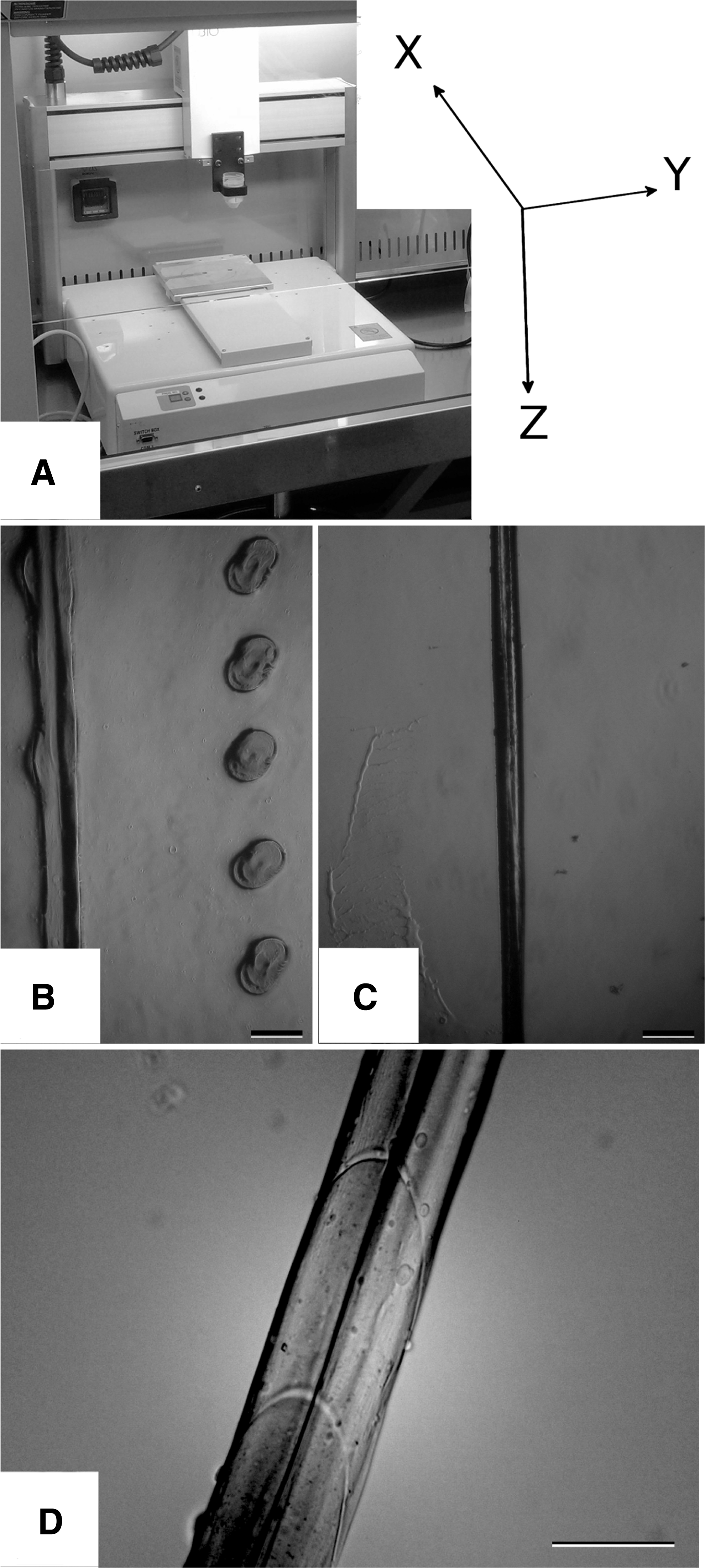
The printer (see Fig. 1A) was carefully cleaned with ethanol and placed under a biological hood. It consisted of a positioning and deposition system that can run independently. The programmable positioning system had three degrees of freedom. Samples were placed on a metal base moving linearly (x) while the deposition head was placed above the base, in a plastic holder moving in y and z. The Petri dish, coated with the gelatin hydrogel containing ions, was placed on the metal base of the printer. This metal base was connected to the ground of the generator.
Deposition of alginate.
The deposition system consisted of a needle with a custom fit that was placed in the plastic holder of the printer above the base and connected to a polytetrafluoroethylene tube with a Luer lock. The tip of the needle was connected to the positive end of the generator, while the other side of the polytetrafluoroethylene tube was connected to a 3-mL syringe loaded with alginate solution and placed on a pump set to a fixed flux. A calibration was performed for each Petri dish to make the z axis of the printer correspond to zero when the needle was in contact with the gelatin coating. To perform the experiments, the pump was started and the generator was turned on when the solution reached the tip of the needle. This triggered the beginning of the printing program. To remove the samples from the coating, warm DMEM was poured onto the sample and the Petri dish was placed in an incubator at 37°C for few minutes to induce the gel-sol transition of the gelatin. After that, the alginate deposition could be easily removed from the gelatin solution using tweezers, washed again, and placed in a flask filled with medium. The flask was placed in the incubator and the medium was changed every day until the end of the experiment.
Agarose mold and alginate dissolution
Some alginate depositions were entrapped in an agarose mold for postprocessing. At first, some agarose was poured to coat the bottom of a 24-well plate and was left at room temperature to undergo the sol-gel transition. Once the coating was obtained, the alginate-printed sample was placed on the agarose hydrogel and more liquid agarose was poured in the wells. The samples were left at room temperature until the second layer of agarose became a hydrogel. Samples were removed with tweezers, placed in a six-well plate containing DMEM, and moved in an incubator.
Alginate was dissolved after 6 days of incubation. First, the supernatant was removed and the samples were washed with PBS at 37°C. A chelating solution containing EDTA was added to remove the crosslinking ions and dissolve the alginate hydrogel. Then, the samples were moved to an incubator for 20 min to allow the complete dissolution of the gel. Finally, samples in the agarose mold were washed again in PBS, placed in a well plate containing medium, and cut with a scalpel to give cells a way out from the hydrogel and observe them readhere on the tissue culture plate.
Confocal microscopy
A live/dead assay with Calcein AM and PI was performed on printed hydrogel samples using standard protocols. In brief the samples were moved with tweezers to a new plate containing medium with a 10% v/v Calcein-AM solution and then the well plate was placed in a dark incubator for 30 min. At the end of the incubation time, the samples were moved to a new well plate and washed three times before adding a 2% v/v PI solution. The samples were left for 3 min protected from light at room temperature and washed again. All solutions used were at 37°C. Observations with the confocal microscope (Nikon A1) were performed in wet conditions; a separate image was taken for each setup. Pictures were taken 1 and 7 days after printing.
Results
Description of printing process
The printing process can be tuned to obtain either single dots or continuous lines. Figure 1B shows two different kinds of depositions obtained with one single run of the printer. This sample was obtained by programming the printer to perform a 100-mm deposition of alginate on a straight line and then moving back on a parallel path increasing the speed of the needle and the flux of solution, but keeping the distance from target and applied voltage constant. Alginate undergoes a fast sol-gel transition upon contact to the gelatin hydrogel containing calcium cations so that a hydrogel immediately forms. The drops that are ejected from the needle, as a result from the impact on the substrate, squeeze on the coating losing their spherical shape; this is clear if the width of the sample is compared with its thickness (the side view of the continuous deposition is shown in Fig. 1C). Subsequently the cations diffuse in the alginate leading to a complete sol-gel transition of the whole bead. The straight line results from the coalescence of closed-packed beads, as evidenced in the optical microscope image in Figure 1D where the boundaries between the beads can be recognized.
Similarly to gelatin, alginate hydrogel can act itself as a source of crosslinking ions. This permits obtaining thick samples with a layer-by-layer deposition. In fact the top layer can crosslink due to the ions coming from the substrate below, being it gelatin or a previously printed alginate layer. Anyway the printing speed has to match the diffusion rate, which will decrease with the thickness of the construct. The thicker the deposition is the more time is needed to obtain a sol-gel transition of the last-deposited layers. For these reasons a pause could be necessary after each layer, in case that the ion diffusion speed is not sufficient to fully gelify the alginate. This is particularly evident for small samples where the layer trajectory is short and it is necessary to pause the process to avoid the deposition of alginate solution on top of a still partially liquid layer of alginate. If the sample is big enough and, as such, the printer takes more time to complete each layer, then this pause is not necessary.
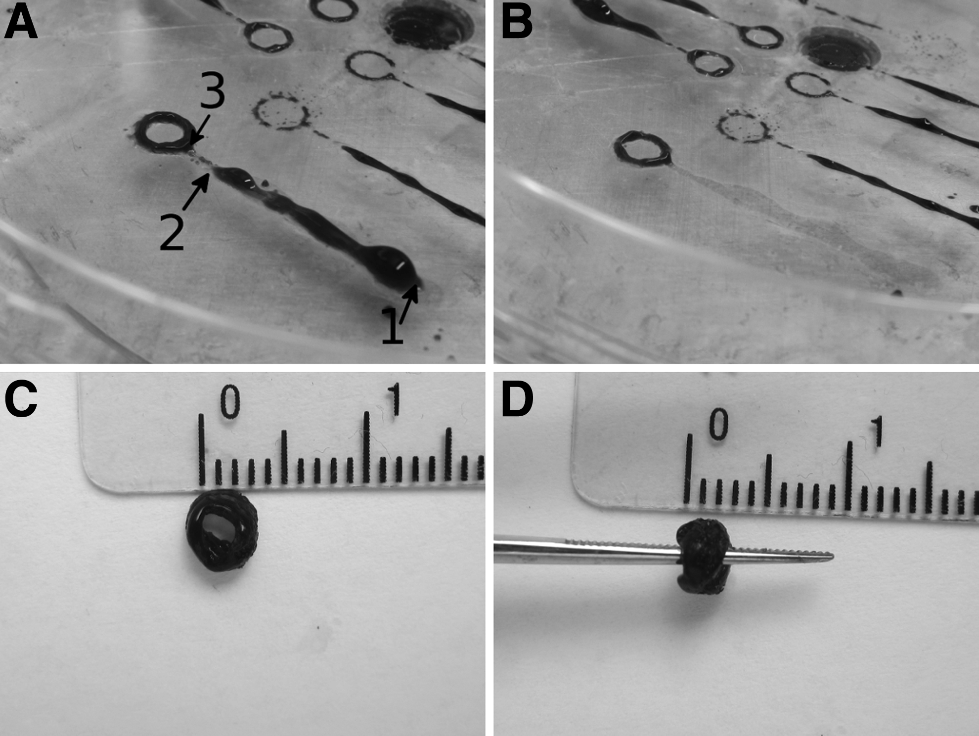
Moreover once the generator is turned on, a short time is needed to establish a regular jet of drops, so it is not possible to predict when the first drop will be ejected from the needle. For this reason it was convenient to plan the deposition including an extra trajectory to build up a sacrificial part to be easily removed at the end of the printing process. Figure 2 shows parts of the procedure to obtain a small multilayered cylindrical structure with a radius equal to 1.5 mm (distance from the center of the cylinder to the center of the deposition, estimated error of 10%). First, the needle slowly moved in a “standby area” (zone between points 1 and 2) to allow enough time for the sol-gel transition of the previously deposited layers. Then, it rapidly accelerated in a zone between points 2 and 3 to limit material deposition and facilitate the removal from the final construct. Once in the deposition zone (circular ring after point 3), speed was set for optimal deposition. Full 3D fabrication can be obtained by overlapping multiple layers, repeating the procedure and progressively increasing the “z” coordinate of the needle. By following this procedure, it was possible to print structures up to 2-mm height, enough to allow an easy addition of a solution of calcium-enriched gelatin to the side and into the middle of the sample. By adding more gelatin, it is possible to sustain more layers and as such to sustain taller structures. This way the potential limit of calcium diffusion inside the gel can be overcome. A similar microfabricted structure was proposed by Teramura and Iwata to build macrocapsule loaded with Langerhans islets as an artificial pancreas. 31
Printing a “small, thick sample.”
Process parameters
The EHDJ printing process is influenced by parameters, such as the flux of solution flowing through the needle, the potential applied, the speed of the needle in the x and y planes, and the distance between the tip of the needle and the top of the gelatin coating underneath it. The speed of the needle was found to have a strong influence on the characteristics of the printed samples so we tested all the aforementioned parameters versus speed, ranging from 1 to 6 mm/s. As a starting setup, we printed samples at 14 kV, 10 μL/min at a distance of 5 mm varying one single parameter for each experiment.
Flux of solution versus speed
By increasing the flux of solution from 5 to 10 and 20 μL/min, more deposition was continuous and thicker (Figure 3). At 5 μL/min, the tendency was to obtain dotted depositions, partially bridged together at low speeds. At 20 μL/min, the tendency was opposite and more continuous deposition could be obtained with only one dotted printed line at the highest speed tested (6 mm/s). At 10 μL/min, the depositions were continuous at lower speeds, while becoming aligned dots at higher speeds. All the tested samples did not present any deviations from a straight line. For each set of samples, it was possible to observe an inverse relation between the speed of the needle and the diameter of the deposition, with thinner depositions obtained at higher speeds. Together, as expected, depositions were generally thicker at higher fluxes. For example, it was possible to observe dots with a diameter of 298±5 μm at 5 μL/min and 6 mm/s speed increasing up to almost 600 μm when the flow of solution was set at 20 μL/min.
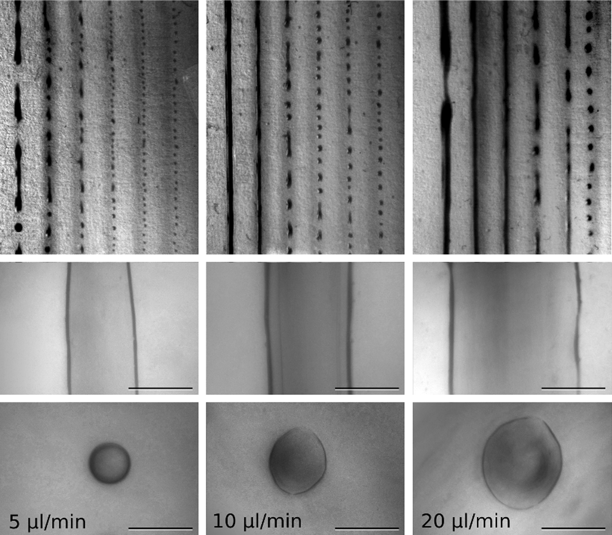
From left to right depositions at 5, 10, and 20 μL/min. Top row shows the geometrical feature of the depositions varying the needle speed from 1 to 6 mm/s. Middle row shows depositions obtained at 1 mm/s while bottom row shows depositions at 6 mm/s. Scale bar is 500 μm.
Voltage versus speed
The tested voltages ranged between 12 and 20 kV with increments of 2 kV. At 12 kV, a proper jet of drops could not be established as shown in Figure 4; single beads were deposited by gravitational dripping and they were closer to each other at lower speed. From 14 kV upward, the jet of drops could be established. By further increasing the voltage, a certain degree of disorder appeared on the printed samples. At 20 kV, the voltage was too high to obtain an ordered deposition, with all the deposition lines resulting misaligned and irregular.
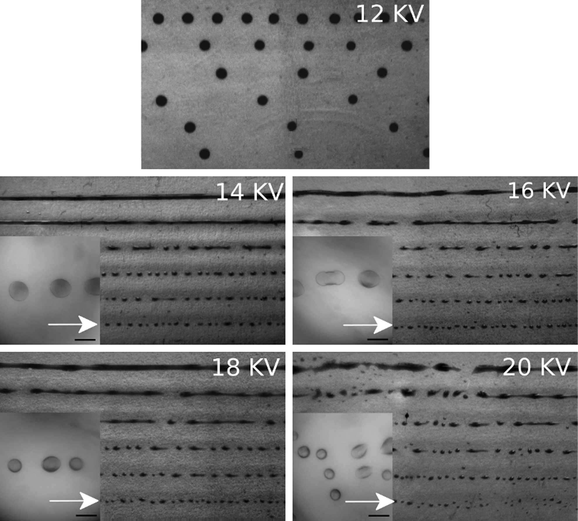
Each of the five pictures shows the geometrical feature of the depositions varying the needle speed from 1 (top) to 6 mm/s (bottom). Magnification shows depositions obtained at 6 mm/s. Scale bar is 500 μm.
Distance from target versus speed
The tested distances from target ranged between 4 and 7 mm (Figure 5). At 4 and 5 mm, results were quite similar, with two continuous lines in each sample at 1 and 2 mm/s and dotted lines at higher distances. All 12 depositions (either continuous or dotted lines) were uniform and straight. By increasing the distance from target over 5 mm, the beads ejected from the needle tended to aggregate in spots, leading to deposition lines with a diameter that changed along the deposition path. At 7 mm, it was possible to observe evident deviations from a straight line. For distances under 4 mm, the tip of the needle was too close to the gelatin target and causing spark generation, thus inhibiting the formation of the jet.
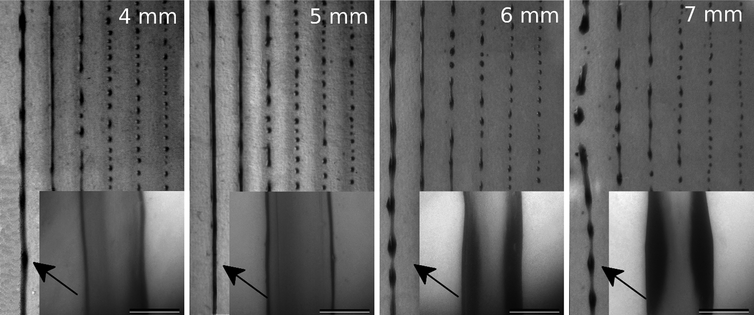
From left to right depositions at a distance of 4, 5, 6, and 7 mm. Each of the four images shows the geometrical feature of the depositions varying the needle speed from 1 (left) to 6 (right) mm/s. Picture insets refer to the depositions obtained at 1 mm/s. (as indicated by the arrows). Scale bar is 500 μm.
Printed samples with cells
Samples were realized setting the printing apparatus to the best working conditions. The voltage was set at 14 kV because it was the only value giving straight deposition lines of beads among the five tested. The flux of solution was set to 10 μL/min, being the best balance between throughput and spot size. The distance from the target was set at 5 mm that, together with 4 mm, gave the best uniform and straight deposition. The needle speed along the x, y plane, a parameter that does not affect cells, was arbitrarily chosen at 4 mm/s. An alginate suspension containing 5×10⁶ cells/mL was used. All samples were made of five layers and printed on a gelatin-coated Petri dish.
Samples were cultured for 1 and 7 days before observing them with the confocal microscope after Calcein AM and PI staining. As shown in Figure 6, in both cases, they were able to maintain entrapped cells viable and evenly distributed.

Deposition of cell-laden alginate after 1 day (left) and 7 days of culture (right); confocal microscopy live/dead assay (green/red) with calcein AM and propidium iodide (PI). Scale bar is 100 μm. Color images available online at
Some samples were molded in agarose to show that cells retain the ability to expand once released from the printed alginate. In this case the alginate was dissolved at day 6 and, after being cultured for one more day on a tissue culture plate, they were observed with confocal and optical microscope. As shown in Figure 7 the dissolution of the alginate was effective and cells, without the matrix supporting them, lost their 3D distribution. Cells formed a two-dimensional layer at the base of the volume left from the dissolved alginate. When the mold was cut, cells from this layer were able to move outside and readhere on the tissue culture plate.

Optical (left) and confocal (right) images of alginate deposition after 7 days from cell encapsulation. Confocal images after calcein AM and PI staining showing living (green) and dead cells (red). (Upper left) Optical microscope image of alginate-cell suspension. (Upper right) Three-dimensional (3D) confocal image of alginate deposition after 7 days from deposition showing the distribution of cells inside the alginate; green spots are living cells. Bottom left optical microscope image of cells outside the agarose mold and readhering on the tissue culture plate. (Bottom right) 3D confocal image of the agarose mold taken after 7 days from deposition showing that the dissolution method was effective in removing the alginate matrix that sustained the cells; green spots are living cells. Scale bar is 250 μm. Color images available online at
Discussion
It is generally difficult to predict quantitatively the outcome of electrohydrodynamic processes. For example, by changing the concentration of a biomaterial in solution, the electrical and rheological properties of the solution change affecting the outcome of the process. Similarly, changing the printing parameters, such as voltage and flux of solution, leads to differently printed samples. Some mathematical models of the described process exist, but their application is not immediate for a non-Newtonian fluid (alginate) containing particles (cells). However, general qualitative information can be drawn 32 by observing the samples obtained with the printer.
Considering the voltage, it was possible to initiate the jetting condition starting from 14 kV. Below this value we observed only the acceleration of the dripping rate from the syringe, without any effect on the diameter of the drops. It should be noted that, with our setup, higher voltages were needed to obtain jetting conditions, compared to data found in literature regarding cell encapsulation experiments using EHDJ (6–7 kV). 33 In these experiments beads are ejected directly in a calcium chloride bath, while in our setup beads were ejected onto a gelatin hydrogel. We believe that the presence of the gelatin between the cathode and the anode mitigates the effect of the applied voltage. In fact it was observed that the jetting condition can be initiated only at a certain distance from the gelatin substrate, while, moving the needle closer, it suddenly stops, to start again after the gelatin was removed.
With the voltage set at 14 kV, the depositions obtained were straight and uniform. By increasing the voltage, the depositions were less uniform. At 14 kV and needle speed of 6 mm/s (Fig. 4), the average diameter was 450±16 μm, while at 20 kV it was 268±75 μm. At 20 kV the average diameter was smaller, but the dispersion was higher. In fact it was possible to observe the presence of much smaller beads. This observation is consistent with the results obtained by Hayati et al. 34 who showed a decrease in the average diameter of the jet with increasing voltages. Moreover, as suggested by Cloupeau and Prunet-Foch, 35 a high voltage can generate an unstable Taylor cone and secondary disintegration, leading to beads characterized by a small size and high dispersion.
In EHD processes, the flux of solution, as observed by Hwang and colleagues, 36 plays a crucial role, with higher fluxes generating bigger beads and as such bigger building blocks. In the EHDJ printing, a high flux of solution is necessary to obtain a high throughput but this leads to thicker depositions and, consequently, to a lower printing resolution. For example (Fig. 3), with a flux of solution of 20 μL/min and a needle speed of 1 mm/s, the average diameter was about 960±120 μm, while at 5 μL/min the average diameter of the deposition was 512±68 μm. On the other side it was possible to partially mitigate this phenomenon by increasing the speed of the needle; in fact at 3 mm/s and a flux of 20 μL/min, the average diameter became 598±59 μm.
Shorter distances are generally preferred since the droplets, once ejected, are subjected to perturbations that influence their trajectory, leading to placement errors. 16 In fact at higher distances the deposition appeared less regular. For EHDJ printing, typical working distances found in literature are in the submicrometric range 37 but typically the samples are printed on top of a dry substrate like a silicon wafer. If the distance is too short, then electric discharge occurs, with the formation of an electrical arc between the needle and the substrate. In our experiment (using a water-based solution printed on top of a substrate with high water content) the minimum working distance possible was 4 mm. This means that at short distances (3 mm) it was not possible to overcome the Rayleigh that determines the jetting condition because of the formation of the arc itself.
In our setup, the best distance possible was found to lie between 4 and 5 mm (both settings gave similar results). When the distance of the needle from the substrate was higher, the drops showed an elliptical shape once deposited on the substrate. For example (Fig. 5), at 5 mm and with a speed of the needle of 6 mm/s, the ratio between the major and the minor axes was between 1 and 1.2 for most of the observed drops while at a 7 mm the range increased up to 1.8.
Other parameters characterizing the process, like polymer concentration, density of cells, and diameter of needle, and their effect on the EHDJ process were previously characterized. 38 In brief, the density of cells in the starting solution influenced the EHDJ process; for example, solutions with higher cell densities (10–20×106 cells/mL) needed a higher voltage to establish a jet of drops. However once the jet of drops was established, there were no substantial differences on the diameter of the ejected beads. The diameter of the needle was chosen to match the best compromise between viscosity and printer spot size, since higher diameter allowed higher solution flux, but increased the spot size of the printer, creating bigger beads. The best alginate solution concentration was found to be 2%. Higher concentrations were possible, but the increase of viscosity had to be balanced by decreasing the flux of solution. On the other hand, lower concentrations were problematic because lower intermolecular cohesive interactions led to secondary disintegration of the jet and, as such, to irregular depositions. Once the concentration of alginate was set at 2%, we empirically found that the optimal concentration of calcium chloride to obtain thicker multilayer samples was 400 mM. In fact, according to results found in literature,39,40 when a solution of alginate is placed in contact with calcium chloride, higher concentrations of salt solution favor the diffusion of the solute and, thus, the formation of thicker hydrogels. Further, faster gelation times are obtained using higher concentrations of divalent cations in solution. The concentration of calcium ions we used was higher than the physiological one and this may affect cells. It should be noted that the printing procedure was relatively fast but further studies may be needed to assess the effect of such calcium concentration on cell behavior.
Cell viability was evaluated by means of confocal microscopy. We did not observe substantial differences between samples at day 1 and samples at day 7 in terms of number of living cells. This is partially expected and can be explained considering that the proliferation of anchorage-dependent cells, such as fibroblasts, is inhibited in alginate since it does not present adhesion motifs and its hydrophilic nature discourages the adsorption of cell adhesion proteins. 25 This observation is consistent with the results obtained by Ma et al. 41 who showed that cells in alginate microcapsules are in a semiquiescent state. They observed a marked increase in the percentage of cells in G0G1 phase together with a decrease in the percentage of cells in S and G2M phases. For applications where cell adhesion and matrix degradation are needed, alginate can be modified to tune its degradation kinetics42,43 and to include cell adhesion motifs. For example, Yu et al. 44 demonstrated that RGD peptides conjugated to alginate improved human umbilical vein endothelial cell adhesion and proliferation when compared with an unmodified control. The results of our observation by confocal microscope were also consistent with our previous observations on cells encapsulated by EHDJ that showed a low number of dead cells up to 30 days after encapsulation. 38 This suggests, as initially hypothesized, that the EHDJ technology to encapsulate cells can be safely transferred to a bioprinter and assemble in one single step, cell-laden devices/scaffolds that can sustain cell survival.
In Table 1 we report some features of the printer used in these experiments and compared them with other printing systems found in scientific literature. 13 This table collects only the few features reported for these printers. For example, it does not take into account the ability to print directly 3D structures that, in some cases, is missing. Being bioprinting a relatively new technology, it is not yet clear which printing systems among these is best suited for a specific application. In fact the aforementioned printers have been used for a wide variety of application using different kind of cells, like neurons, fibroblasts, endothelial cells, and stem cells.45–47 In the inkjet and syringe extrusion printers, a fluid is forced out of an orifice, typically smaller than 100 μm, creating droplets of 300 μm or more. The droplet size is comparable to that of the EHDJ printer, 9 suggesting that these printers may be characterized by a similar resolution. By the way the high-voltage-driving technology may also be improved to reduce the final spot size, accordingly to results found in literature, and, as such, to obtain much higher resolutions. 48
Tested but not reported.
EHDJ, electrohydrodynamic jetting.
A clear advantage of using EHDJ printers, when compared with inkjet printers, is the fact that they can be used for processing a wider range of suspensions. In particular they can be tuned for highly concentrated suspensions (high material loading/high cell density) at the “small” price of a reduced throughput. 49 In spite of some limitations, inkjet printers rely on a cheap but advanced and established technology developed for desktop printers that allow, for example, to use four different materials or suspensions at the same time (corresponding to the RGB and black reservoirs for the ink) and manufacture more complex, biomimetic samples. On the opposite side, laser printers are the most complex printers among the available technologies. In laser printers, an electromagnetic beam with a diameter width of few microns induces the transfer of cells from specifically engineered substrates to a close target, creating droplets of cells smaller than 100 μm. The target is coated with a hydrogel to avoid drying effects and excessive shear forces 50 and 3D printing is usually obtained by transferring one or few layers of cells and coating them with new hydrogel. These printers are characterized by high resolutions that allow the precise patterning of single cells to manufacture complex structures. These kinds of resolutions are difficult to be obtained by other printing techniques, making laser printers ideal candidates when high resolutions are needed (e.g., complex microvascular structures). On the other side, considering the setup of these printers, to obtain 3D structures bigger than few layers of cells may be more challenging. The maximum cell throughput of EHDJ printing is among the highest of the printers reported in literature. The loaded volume of the printer depends on the syringe used on the pump that can mount up to 50-mL syringes. This high load volume, not available in all other systems, allows uninterrupted printing for extended periods of time. Another aspect not present in all other printers is that the part of deposition system on top of the biopaper is small, being constituted of simple and low-cost components: a needle, a cable, and a tube. The most expensive element of the deposition system is the high-voltage generator, which is however a common component available in many research laboratories. Further, EHDJ printer can work on samples that are not perfectly planar because there is a 1-mm range of suitable operating distances, easing the complexity of a precise z mapping of the substrate.
In this proof-of-concept study, alginate was used as a bioink because it is widely used for cell encapsulation and it is characterized by a fast sol-gel transition. In fact when a drop of alginate reaches the target, divalent cations crosslink the surface of the alginate solution in contact with the substrate, locally increasing its viscosity and practically “gluing” the drop on the target. We believe that this printing technique could be applied also to other materials like photocrosslinkable hydrogels. There are many examples of these polymers used for cell encapsulation, such as blends of poly(ethylene oxide) and poly(ethylene oxide) dimethacrylate 51 and RGD incorporating poly(ethylene glycol) diacrylate. 52 Some of these polymers can form a jet of beads 53 and in some cases the sol-gel transition is relatively fast (15 s 54 ), making them potential candidates to be used as bioink for an EHDJ printing technique targeted at specific applications.
Overall, EHDJ printing is a technique capable to create viable cells containing 3D structures and it has the potential to be considered as a valid alternative to more established bioprinting methods. Further work is required to adapt this technique to specific applications, where different combinations of bioinks and biopaper may be needed. An example is the possibility to realize a nerve conduit by integrating a hollow cylindrical scaffold containing glial cells able to recreate a suitable chemical environment, a physical constrain, and a guide for axon regrowth in the cavity.55,56 Another possibility deals with the realization of pancreatic-islet-loaded devices, able to release insulin as a response to glucose concentration.6,31
Conclusions
In this study we demonstrated that the electrohydrodynamic process can be exploited as the deposition system to print alginate hydrogels containing living cells. By optimizing the printing parameters, it is possible to obtain and control a jet of alginate beads that can be placed precisely on a target substrate. If the surface is a hydrogel containing divalent cations, then the alginate crosslinks upon contact without the need of further processing. The printing process is compatible with cell survival and allows the deposition of 3D constructs. The ability to build such constructs could facilitate the design and manufacturing of scaffolds with predefined 3D shapes that may find significant applications in the field of tissue engineering.
Footnotes
Acknowledgment
The authors would like to thank Biotools srl (a spin-off of the University of Trento, Italy) that lent the desktop robot.
Disclosure Statement
No competing financial interests exist.