
Abstract
Controlling the mechanical environment in bioreactors represents a key element in the reactors' optimization. Positive effects of fluid flow in three-dimensional bioreactors have been observed, but local stresses at cell scale remain unknown. These effects led to the development of numerical tools to assess the micromechanical environment of cells in bioreactors. Recently, new possible scaffold geometry has emerged: granular packings. In the present study, the primary goal was to compare the efficiency of such a scaffold to the other ones from literature in terms of wall shear stress levels and distributions. To that aim, three different types of granular packings were generated through discrete element method, and computational fluid dynamics was used to simulate the flow within these packings. Shear stress levels and distributions were determined. A linear relationship between shear stress and inlet velocity was observed, and its slope was similar to published data. The distributions of normalized stress were independent of the inlet velocity and were highly comparable to those of widely used porous scaffolds. Granular packings present similar features to more classical porous scaffolds and have the advantage of being easy to manipulate and seed. The methods of this work are generalizable to the study of other granular packing configurations.
Introduction
B
A large diversity of scaffolds have been used and investigated. Highly porous foam scaffolds were extensively used in perfusion bioreactors,17–22 but fiber mesh scaffolds21,23–26 and scaffolds with regular architecture27–29 were also used by several authors. All these scaffolds were massive and porous and cells were seeded by perfusing a cell suspension. In this large variety of 3D porous scaffolds, low inlet flows lead to cell proliferation,17,21 upregulation of genes involved in the mechanotransduction process,19,22 and increase of alkaline phosphatase activity.16,26
However, due to complex internal geometries and flow conditions, mechanical stresses in scaffolds are not homogeneously distributed and cannot be analytically predicted. In this context, numerical tools have been widely used in an attempt to evaluate shear stress levels and distributions within actual scaffolds. Geometries were either determined through microcomputed tomography or created with geometrical objects. Simulations were performed using computational fluid dynamics20,23,30–33 or Lattice-Boltzmann methods.21,34 At efficient inlet flow, the levels of shear stress evaluated with simulation techniques ranged from 10−5 to 10−2 Pa. In 2010, Voronov et al. 35 studied an extensive set of porous scaffolds and determined a specific three-parameter gamma function to predict in a simple way probability density functions (PDFs) of all scaffolds. This function was also validated for other porous scaffolds of the literature.
Recently, packings of particles were also considered as new possible scaffold configurations.36–40 Instead of being massive, they are composed of an assembly of several biomaterial particles on which cells are seeded. In a clinical context, such scaffolds would be more adaptable to the surgical vagaries, in terms of size and shape. They would also be easier to seed and manipulate. Perfusion of such granular scaffolds with a culture medium had positive effects on cell proliferation,36–38,40 bone formation markers,36,37 and mineralization.36–38 However, to date and to the best of our knowledge, wall shear stress has not been investigated through 3D simulations.
In the present work, a packed-column bioreactor composed of a vertical cylinder filled with granular particles was studied. Three types of granular packings were investigated: a packing of cubes (previously experimentally studied in the work of David et al. 36 ), a packing of beads to investigate the effect of geometry, and a bidisperse packing of beads to investigate the effect of porosity. To this aim, 3D computational fluid dynamics was used to simulate the flow within the packed-column bioreactor. The objective was to determine numerically wall shear stress levels and distributions inside these scaffolds and to compare these results with porous scaffolds, as depicted in literature. On a biological point of view, the results of this numerical study will represent a key step in the optimization of the mechanical microenvironment of cells in 3D dynamic culture. Distributions of fluid velocity and wall shear stress on the particle surface were analyzed as a function of inlet flow and particle geometry. The mechanical efficiency of fluid flow was evaluated, and heterogeneity was compared with the three-parameter gamma function proposed by Voronov et al.
Materials and Methods
The aim of this study was to assess mechanical stimulation perceived by cells in a bone tissue engineering packed-column bioreactor 36 designed as a 13.1-mm-diameter vertical Plexiglas® tube filled with coral particles. In this bioreactor, cells were seeded on the surface of the particles and a continuous unidirectional flow of alpha-MEM culture medium was imposed.
Generation of granular packings
Simulation of the flow in a bone tissue engineering packed-column bioreactor requires full knowledge of the scaffold geometry composed by different random packings of particles. In the present study, three types of particles were used: (1) 3-mm-side cubes, (2) 2-mm-diameter beads, and (3) 3.5-mm-diameter beads. In each case, the particles were assumed to be perfect on a geometrical point of view and sufficiently large in regard of typical cell size to assume a flat cell configuration. Three granular packings of cubic and spherical particles were generated with these three types of particles. The three configurations were composed of (1) 51 cubes with a side of 3 mm denoted Ccube, (2) 71 beads with a diameter of 3.5 mm denoted C1bead, (3) 36 beads with a diameter of 3.5 mm mixed with 108 beads with a diameter of 2 mm denoted C2bead. In each configuration, the number of particles was determined with respect to (1) a representative volume of cubic particle packing corresponding to a minimal size defect of 15 mm length and (2) an equal overall surface of the particles close to 2740 mm2 for every configuration, thus providing the same surface for cell attachment. To create all granular packings, the particles were randomly picked one by one and left to fall under gravity in a tube representing the cylindrical bioreactor. This numerical procedure reproduced in a realistic manner the experimental conditions of the filling of the bioreactor. For that purpose, the LMGC90 software based on the discrete element method was used. This software was mainly developed for granular material simulation and all details of this simulation method can be found in Jean 41 and Radjai and Richefeu 42 For each configuration, four random assemblies were generated leading to 12 granular packings studied in the present work. An example of each configuration can be seen in Figure 1.
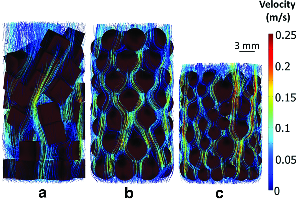
Typical velocity streamlines obtained for one assembly of each configuration Ccube
As the overall surface of the packing was fixed to be equal for all configurations, the average height of C2bead (h=17.6 mm) was significantly smaller than the one of Ccube (h=22.4 mm) or C1bead (h=23.6 mm). The porosity corresponding to the ratio of fluid volume to total packing volume was 54.2%, 49.8%, and 46.9% for Ccube, C1bead, and C2bead configurations, respectively.
Thanks to the data of positions and orientations obtained with LMGC90, the 12 geometries were created in the numerical model and then meshed with the software Comsol Multiphysics 3.4. Particles were considered to be fixed and nondeformable. In all granular packings, the same density of elements on the surface of the particles was imposed to a value close to 40 triangular elements/mm2. This density of surface elements was identified after a preliminary convergence study allowing both accurate simulations and shortened calculation times. Then, the fluid domain composed by the whole cylinder minus the particles was meshed by 3D tetrahedral elements (10-node tetrahedrons, Lagrange P2-P1). In all configurations, the mean tetrahedron density was set to ∼200 tetrahedrons/mm3.
Computational fluid dynamic simulations
In all simulations, the fluid was considered to be homogeneous, Newtonian, and incompressible with a density ρ=1000 kg/m3 and a dynamic viscosity η=1.45×10⁻³ Pa·s.
43
The fluid followed a classical Poiseuille flow at the inlet bottom boundary and the inlet velocity was given by the parabolic equation (1):
where r is the radial position of the fluid particle, ϕ is the inlet flow, and R is the radius of the cylinder. In the present study, five inlet flows were tested: 10, 50, 100, 150, and 200 mL/min corresponding to a mean inlet velocity of 1.2, 6.2, 12.4, 18.5, and 24.7 mm/s, respectively. The top boundary was defined as an open boundary where the atmospheric pressure was imposed. A classical no slip condition was used on all other boundaries corresponding to walls. The flow was simulated in three dimensions inside the bioreactor by solving the Navier–Stokes equations in a steady-state analysis.
Analyses
Analyses were focused on velocity and shear stress values and distributions on the surface of particles. Velocity streamlines were displayed to observe the fluid behavior within the packings of particles, while the wall shear stress norms were computed on every node of the surface of the particles with the following equation (2):
where
The wall stress PDFs for all computational fluid dynamics (CFD) simulations were also generated. Wall shear stresses were normalized using equation (3):
where
Heterogeneity
Any reliable tissue engineering process requires a homogeneous local stress field in the whole of the 3D packing. A radial heterogeneity variable was defined to evaluate the variability of stresses on the particle walls. For each calculation, the model was discretized and mean wall shear stresses were calculated for 20 ranges of radial position. The radial heterogeneity Hr was defined as the standard deviation of these 20 values reported to the overall mean value, expressed in percentage.
Statistical analysis
For each configuration and each flow, four initial random packings were generated and analyzed. In the present study, the mean value corresponded to the average value from the four simulations and the error bars plotted were plus and minus one standard deviation. Statistical analysis was performed using R (the R foundation) with a threshold of 5% corresponding to the alpha risk. A nonparametric Kruskal–Wallis test was used to detect any significant differences between the configurations. If at least one of the configurations significantly differed from the others, a post hoc Conover–Iman test was used to compare the configurations two by two. The influence of the inlet flow on the mean wall shear stress was studied using a Spearman correlation test.
Results
Velocity results
A typical result of 3D velocity field for one assembly of each configuration at 200 mL/min is given on Figure 1. The mean velocity values were 0.045, 0.053, and 0.054 m/s for Ccube, C1bead, and C2bead, respectively. These values should be compared to the mean velocity imposed at the bottom boundary of 0.025 m/s. The highest levels of velocity were recorded in the C2bead configuration. Fluid velocity levels within the construct are dependent on the particles geometry and arrangement.
Shear stress levels
The wall shear stresses on the surfaces of particles are shown in Figure 2 for one assembly of each configuration for every inlet flow. Wall shear stress increased when passing from Ccube to C1bead and to C2bead with a same inlet flow. Obviously, wall shear stress also increased when the inlet flow increased. Localizations of maximum wall shear stresses were similar whatever the inlet flow.

Wall shear stress obtained for one assembly of each configuration Ccube, C1bead, and C2bead at every inlet flow. The fluid circulated from bottom to top of packing. Color images available online at
Figure 3 shows the mean wall shear stress versus the inlet flow for all configurations. Each bar corresponds to the average value of the four granular packing simulations with the associated standard deviation. As expected, the mean wall shear stress increased with the inlet flow. In the considered range of flows, the relationship between the mean wall shear stress and the inlet flow was linear. The slopes were 16.1 (p<0.0001, R2=0.995), 27.5 (p<0.0001, R2=0.995), and 38.6 (p<0.0001, R2=0.998) Pa·s·m−1 for Ccube, C1bead, and C2bead, respectively. Mechanical efficiency of the inlet flow obtained through this slope depended strongly on the configuration. At the same inlet flow, the mean wall shear stress increased by 75% and 40% switching from Ccube to C1bead and C1bead to C2bead, respectively.
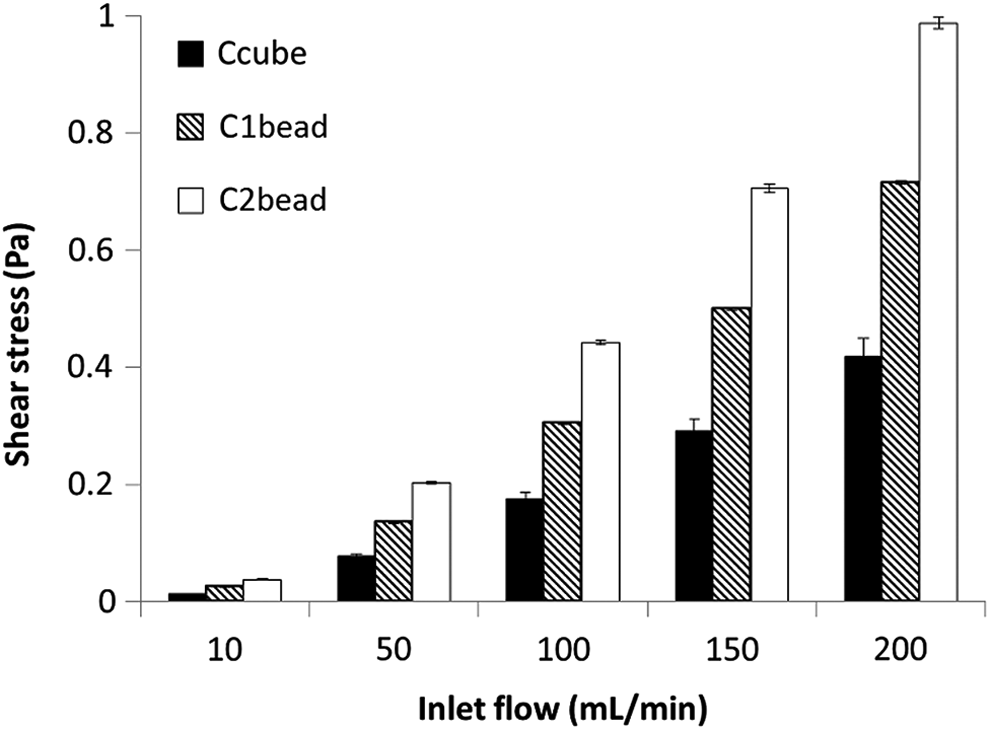
Wall shear stress for Ccube, C1bead, and C2bead configurations at 10, 50, 100, 150, and 200 mL/min. Each bar represents the average value calculated for the four assemblies of each configuration.
Shear stress distributions
On a local scale, the inlet flow played a significant role on the distributions of the wall shear stress applied at the surface of the particles. The distributions are shown in Figure 4 where each bar corresponds to the average of the four granular packings with the associated standard deviation. The distribution for an inlet flow of 10 mL/min was not presented because 100% of the shear stress values were included in the first range of wall shear stress (0–0.2 Pa) for all configurations. As expected, the local wall shear stress increased with the inlet flow. At each flow, the distribution for C2bead was more skewed toward higher shear stresses than the distributions for Ccube and C1bead.
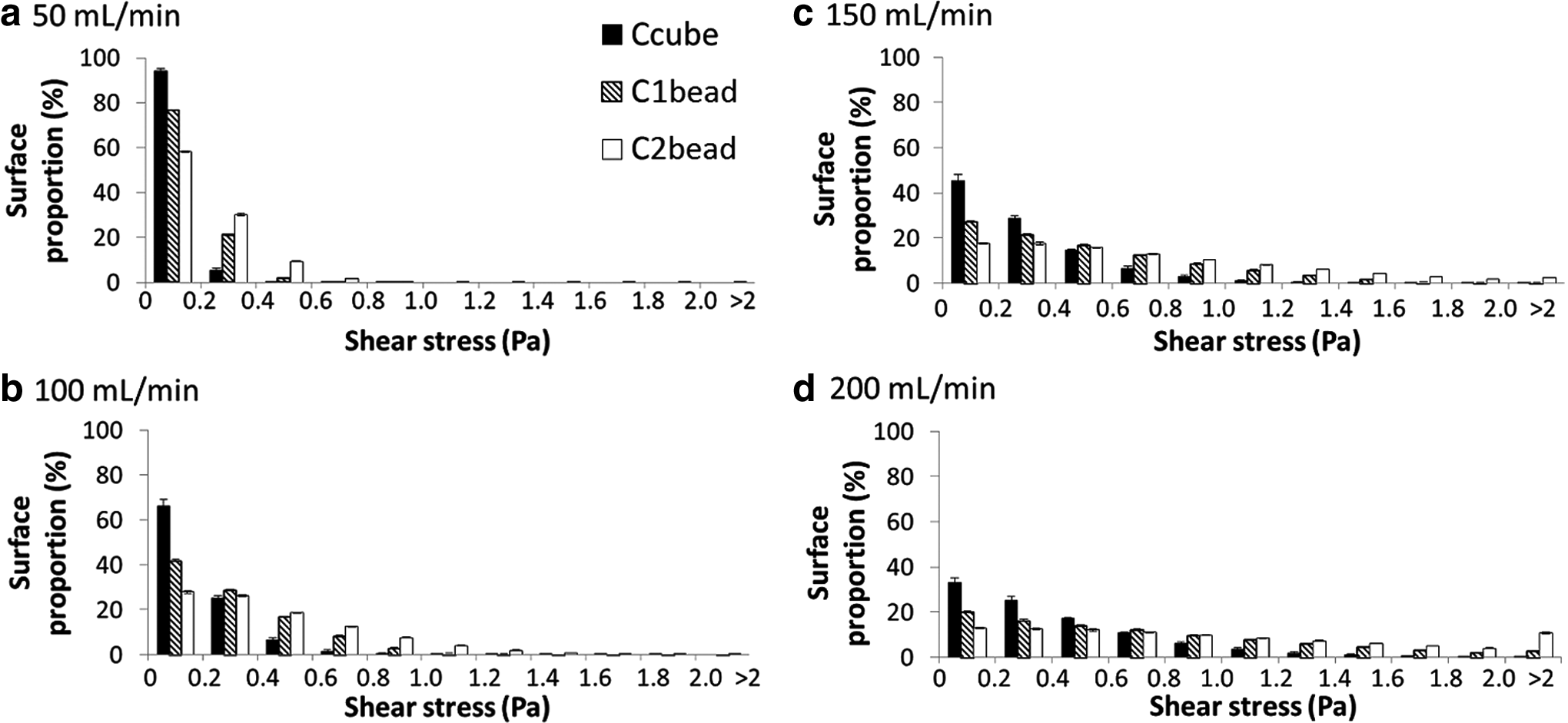
Wall shear stress distribution for Ccube, C1bead, and C2bead at 50 mL/min
Local dispersion analysis
The obtained PDFs for all three geometries of this study are presented in Figure 5. The 1000 dots corresponding to the 50 bins of all four assemblies and five inlet flows are presented in the same figure. All three distributions have a gamma-3p shape. Specifically, Ccube and C1bead both present high frequencies for low shear stresses resulting in a high and narrow peak on the left. This peak is higher in Ccube (0.83) than in C1bead (0.67). The C2bead PDF is wider with a lower maximum value (0.53) and an increased skewness toward higher shear stresses. The dashed line on every graph represents the PDF of stresses Γ(2.91,−1.43,0.45) obtained by Voronov et al. for 36 home-manufactured highly porous scaffolds studied. In the present study, a Kolmogorov–Smirnov goodness-of-fit test showed that the PDF from all configurations followed Voronov's gamma-3P distribution Γ(2.91,−1.43,0.45) with a significance level of 25–30%.
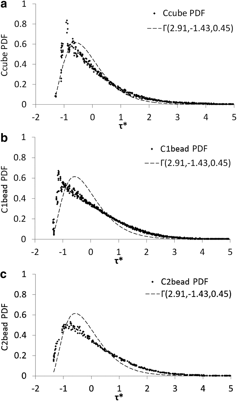
Probability density functions followed by the nondimensional wall shear stress obtained for Ccube
Shear stress heterogeneity
Figure 6 presents the radial heterogeneities obtained for all configurations and all inlet flows. For every inlet flow, Hr was of the order of 15% in C2bead, lower than in the two other configurations (20–30%). For all geometries, Hr slightly decreased when the inlet flow increased.
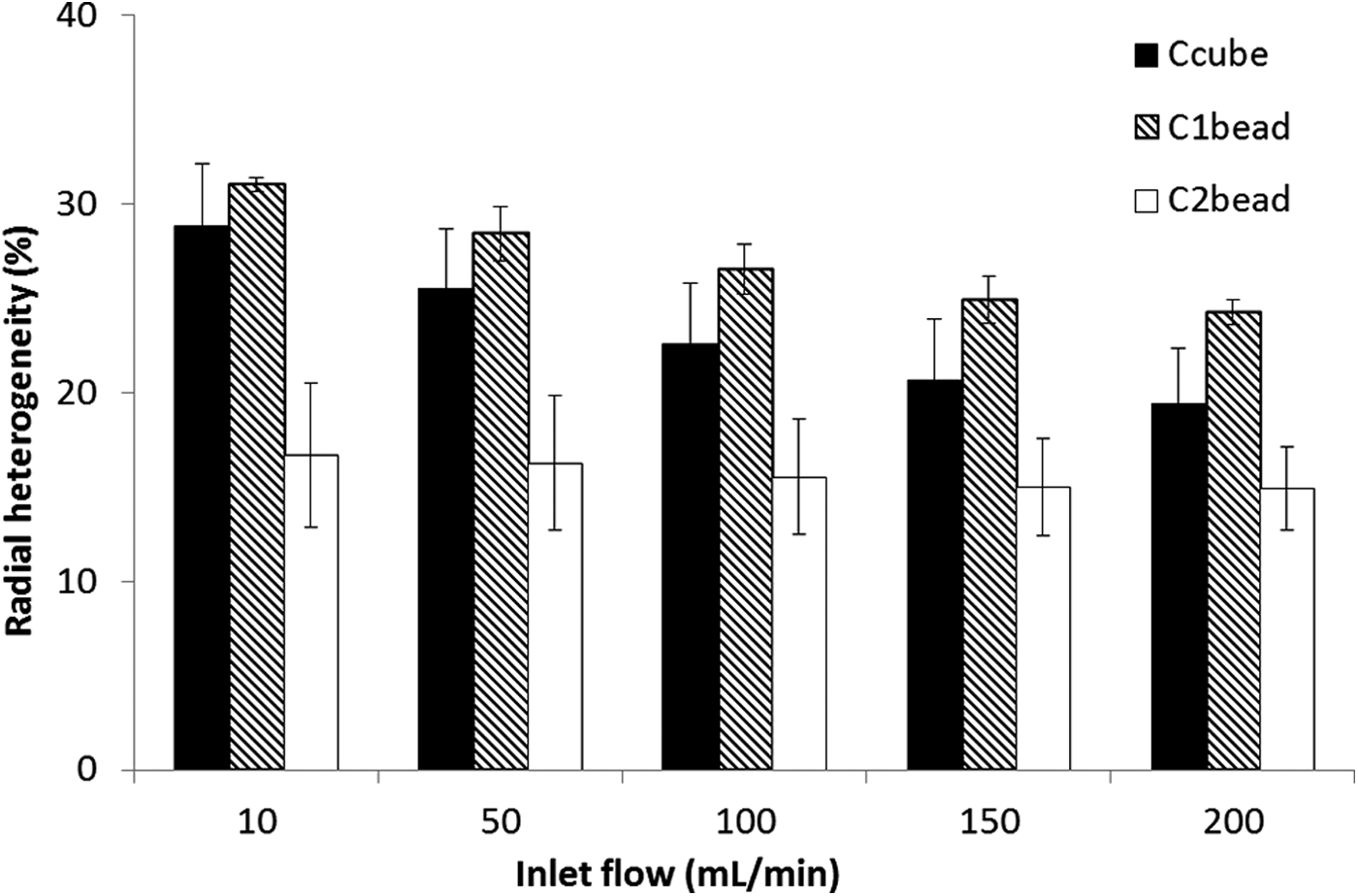
Radial heterogeneities calculated for Ccube, C1bead, and C2bead configurations at 10, 50, 100, 150 mL/min, and 200 mL/min. Each bar represents the average value calculated for the four assemblies of each configuration.
Discussion
In the present study, three porous scaffolds made of cubic or spherical particles of millimeter size were studied. Local shear stresses were calculated using the CFD method for the three granular packings. This present 3D numerical study on shear stress in granular scaffolds highlighted some interesting trails for the future development of such scaffolds. The particle geometry strongly influences fluid velocity, wall shear stress mean values and distributions, mechanical efficiency of the flow, and plays a role on homogeneity of shear stresses within the constructs.
As expected for each packing, a linear relationship between the mean shear stress at the wall and the mean inlet velocity was highlighted. The slope of this linear relationship, denoted Sw thereafter, provides the capability of the scaffold to convert the effect of the fluid flow into mechanical stimulation. Table 1 gives the slopes Sw calculated for the scaffolds of the present study and different scaffolds analyzed in the literature. In this study, Sw appears to be strongly dependent on the scaffold geometry and on the distribution of particle sizes. In particular, the slope of C2bead configuration is twice greater than the value obtained for Ccube configuration.
In the literature, a large number of studies focused on porous foam used as scaffold. These foams are composed with different materials, with a porosity Φ varying from 38% to 90% and a pore size diameter d from 100 to 350 μm. Although highly dispersed, all these foams gave the same order of magnitude of the slope with an average value close to 50 Pa·s·m−1. Goldstein et al. 47 proposed a simplified cylindrical pore model leading to an analytical evaluation of the slope inversely proportional to the pore diameter size and the porosity. This formula roughly predicted the variation observed in the different configurations. Simulations of scaffolds with fiber architecture were scarcer, but the two studies referenced in the table gave an average slope slightly higher than the slope value measured in foam.
The slopes of the granular packings of the present study were smaller compared with literature data, but on the same order of magnitude. These variations cannot be explained by the small porosity decrease observed in granular configurations, suggesting a strong size effect of void space between particles. The typical morphology of granular packing led to a poor definition of pore diameter size. However, the void space was reduced when the number of particles and their contact points increased in a same volume fraction. In this context, the slope of C2bead configuration was naturally higher with more numerous particles. This result suggests that the slope of granular packing could be improved either by using a larger distribution of particle diameters or by using smaller particles. However, granular size diameter governed the rate of dissolution of the construct and needed a minimum size threshold.
Recently, Voronov et al. developed a new method based on PDFs to evaluate a priori the stress distribution of highly porous scaffolds. In particular, these authors showed that three-parameter gamma PDF Γ(2.91,−1.43,0.45) fits PDF of stresses obtained in 36 home-manufactured highly porous scaffolds studied and validated other porous foam scaffolds from different laboratories.20,48,49 This new method was validated on granular packings used in the present study showing that PDF from all configurations followed the same gamma-3P distribution. This study proved that granular packing scaffolds followed the same PDF as massive porous scaffolds. In Ccube and C1bead, a high frequency peak was observed close to −1 normalized stress suggesting a more ordered microstructure. 50 To date and in our knowledge, PDF of wall shear stresses in scaffolds with porosity of the order of 45–55% was only studied by Pham et al. 50 In this work, authors found that for the most random configurations and with a porosity lower than 60%, the PDF still followed the gamma-3P distribution but with a shape modification: a high frequency peak close to −1 normalized stress occurred, the decrease classically observed at the left of this point disappeared, and this effect was more pronounced as porosity was decreased. Based on these results, the absence of any peak in the C2bead configuration revealed, as expected, a more random geometry and suggested that other bead size distributions leading to smaller porosity could be acceptable.
The heterogeneity analysis showed that the C2bead configuration provided more homogeneous stress within the constructs compared to the two other configurations. It is likely that the addition of smaller beads in C2bead compared to C1bead reduced and homogenized pore size and shape in the packing and, consequently, strongly reduced the heterogeneity. This is very important from the point of view of bioreactor design as the homogeneity of the stresses is directly related to the homogeneity of cell adhesion and production of extracellular matrix.
In the present study, the initial scaffold geometry was defined using a numerical Discrete Element Method consisting of randomly picked particles one by one into a set of defined particles. This original procedure was rapid and easy to implement compared with the microcomputed tomography approach. One limitation of the method used in the present study was the perfect characteristics of the particles and the lack of roughness at the surface of particles. However, to our knowledge, the submicrometer roughness effect on wall shear stress was not analyzed in the different porous scaffold simulations due to limits imposed by the microcomputed tomography resolution. Taking the roughness into account was not within the scope of this study, but creating a setup of rough particles in place of perfect particles is technically achievable.
In 3D scaffolds, beneficial fluid flow effects were observed and reported in literature for shear stress values ranging from 10−5 to 10−2 Pa. Cell proliferation, production of extracellular matrix, activation of proteins, and expression of some genes related to mechanotransduction were frequently reported in literature with these stress levels.19,22,24–26 In the present study, such levels of stress were reached at 10 mL/min in all configurations. However, this level of stimulation is rather different from the values of shear stress in vivo 0.8–3 Pa 51 or in two-dimensional experiments ranging from 0.3 to 2 Pa.12,52,53 The device studied in the present work, a packed-column bioreactor filled with a granular packing scaffold, enables levels of stimulation of this order of magnitude to be reached. The high inlet flows required to reach these levels indicate that intermittent flows are to be planned. A discontinuous loading composed with alternating sequences of low and high flows would be comparable to in vivo loadings with alternative activity and rest phases.
In conclusion, scaffolds composed with granular packings were equivalent in terms of fluid flow mechanical efficiency and stress distribution, but would be advantageous in a clinical context. The C2bead configuration is the best among the three tested in the present work in terms of efficiency and homogeneity. The numerical method proposed in this work could be directly applied to the distribution of other particles to optimize scaffold regarding these criteria. In future experimental work, effects on cell proliferation, bone formation markers, and mineralization of the three granular packing will be analyzed.
Footnotes
Acknowledgments
This project was supported by the French National Agency. The authors acknowledge financial support from ANR OMBIOS (ANR-11-BS09-0036). They also wish to thank the IVTV platform (ANR-10-EQPX-06-01).
Disclosure Statement
No competing financial interests exist.