
Abstract
Numerous studies have shown the capabilities of three-dimensional (3D) printing for use in the medical industry. At the time of this publication, basic home desktop 3D printer kits can cost as little as $300, whereas medical-specific 3D bioprinters can cost more than $300,000. The purpose of this study is to show how a commercially available desktop 3D printer could be modified to bioprint an engineered poly-
Introduction
W
3D bioprinting has the capacity to be utilized in various applications in which living scaffolds are needed, such as tissue engineering and regenerative medicine, transplantation and clinics, drug screening and high-throughput assays, and cancer research. It has been used to fabricate bone, cardiac tissue, cartilage, heart valves, liver organoids, lung tissue, pancreatic, skin, vascular tissue, and many other tissue types, both composite and noncomposite in nature.3–5 The 3D porous scaffold designs that are brought to life with bioprinting allow for improved cell–cell contact, cell–matrix interactions, and increased cell densities when compared with cells grown in 2D culture. 6 These efforts have been met with some success in various applications, but the medical-specific 3D bioprinters needed to do this work can be very expensive. 7
The cost of 3D bioprinters can range from $10,000 to as much as $300,000 according to manufacturer's pricing charts available online. The lower cost printers contain a single extruder, which poses limitations for printing more complex structures that require multiple inks and/or cell types. The current cost of high-quality 3D bioprinters can be prohibitively expensive for many research facilities. We believe that 3D bioprinting has the potential to produce tissue and organ replacements and will ultimately be essential to the future of medicine. However, it is imperative to create a low-cost high-quality 3D bioprinter to expedite the adoption of this technology. To create such a printer, we believe that a commercially available desktop 3D printer can serve as the base for modifications. The selected printer should contain an open frame, capability for varying temperatures, and adjustable travel speeds to be considered for this type of modification.
Current research in the field focuses on the advancement of printers and biomaterials that are capable of producing biomimetic scaffolds. We hypothesized that engineered poly-
Materials and Methods
Design of machine
A MakerBot Replicator® 2X Experimental 3D Printer (Rep2X) (Makerbot, Brooklyn, NY) was modified for use in this study. One of the extruder head units was removed and retrofitted with a syringe injection unit (SIU). The SIU's syringe attachment, housing, guides, and motor mounts were templated in Rhino3d™'s Wenatchee-OsX CAD designer (Fig. 1). Before modification, the SIU was 3D printed on the Rep2X 3D printer. The SIU was designed to create a method of advancing and retracting a syringe to extrude bioinks. The SIU's design was optimized to automatically and precisely inject the bioink into the scaffold while utilizing the standard operating software of the Rep2X.

Modified MakerBot® Replicator™ 2 × 3D printer:
The over arching concept is to be able to connect the SIU directly into the stock-mounting block of the Rep2X (Fig. 1). The stock motor mount screws were recycled to attach to the SIU. A diagonal cutout was created to allow for full x and y axes travel. The syringe holder attaches to the lead screw and a smooth rail of the SIU and the plunger of the syringe connects into the adapter when ready to use (Fig. 1). The syringe connects through a leur lock to a needle extender (Sklar Corp., West Chester, PA) that has been modified by a tap and die to allow easy attachment and removal to the mounting block (Fig. 1). All of the parts that come in contact with bioinks are removable and can be autoclaved or are disposable. The modifications contained a lead screw, linear motion shaft, and bearing to allow for smooth travel of the syringe during the bioink extrusion process. The version of the SIU incorporated the stepper motor and wiring in its design (Fig. 1). The stock motor is a NEMA 17 unipolar stepper motor and the lead screw is a M8 axis screw. The printing heads were completely disassembled except leaving one heating unit in place (Fig. 1). The SIU was bolted into place after its assembly (CAD files are available in Supplementary Data; Supplementary Data are available online at
In addition to the SIU, an oiler and an additional polymer cooling fan were added to the stock extruder head of the Rep2X to allow the machine to accept polymers for which it was not originally designed (Fig. 3). A printer profile from Makerware™ was adapted for the SIU and extruder nozzle on the modified machine. The profile can be modified at any time for adjustments to changing materials and desired resolutions. The software is available to download at (
Printer calibration
Twenty 15 mm cubes were designed and printed on a stock Makerbot Replicator Desktop Printer in the “high resolution” profile from the stock settings and with the profile already listed on the modified Rep2X (Fig. 2A). Actual measurements of the printed cubes were taken with digital calipers at three points on the x, y, and z planes. In addition, twenty 18.5 mm “waffle” patterns with 4 mm boxes were created in CAD and printed using the SIU portion of the modified Rep2X out of an alginate bioink (Fig. 2B). Photographs were taken and the x and y axes were measured using ImageJ software (NIH, Bethesda, MD). Also, the printer head's travel distance was analyzed with a pair of digital calipers to ensure that the distance listed on the machine's display was the actual distance traveled. All data were analyzed statistically using StatPlus™ software.
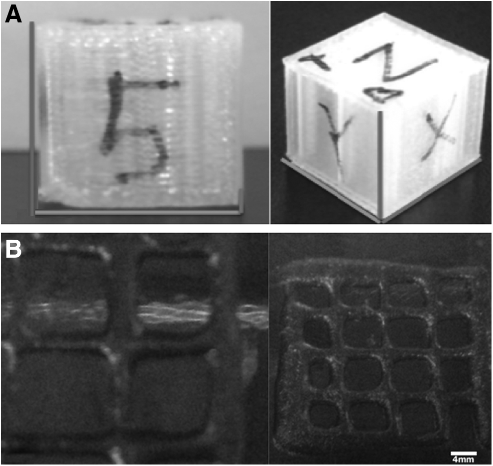
Image analysis
The software ImageJ (NIH, Bethesda, MD) was used for image analysis of size. Pixel length was set to the appropriate scale, measured virtually, recorded, and analyzed statistically using StatPlus software.
Cell sources
Articular chondrocytes were harvested from five Sprague Dawley® rats knees by careful dissection. The cartilage tissue was washed three times with a 10× antibiotic–antimycotic solution (Cellgro, Manassas, VA) for 5 min each time and then minced with a sterile pair of tweezers and a sterile scalpel. Collagenase (NB4 standard grade [1 PZ U/mg]; Serva Electrophoresis, Heidelberg, Germany) was dissolved in 1× DMEM to create the collagenase solution (2.4 mg/mL). The minced cartilage was added to the collagenase solution and transferred to a spinner flask for digestion at 37°C for 4 h. After digestion, the cell suspension was sieved through a 100 μm cell strainer twice. Undigested pieces of tissue were discarded. The cell suspension was centrifuged at 1,500 rpm for 10 min, counted, and plated in culture at a density of 10,000 cells/cm2. Cells were cultured at 37°C, 5% carbon dioxide (CO2), and 95% humidity.
Bioink production
Collagen type 1 gel was produced by combining 8 mL of PureCol Purified Bovine Collagen Solution (3.1 mg/mL) (Advanced BioMatrix, San Diego, CA) with 1 mL of 10 × RPMI (Sigma-Aldrich, St. Louis, MO). Alginate gel was produced by adding 400 mg of low-viscosity sodium alginate (Sigma) to 10 mL of deionized water. After mixing, this solution was passed through a 0.22 μm filter for sterilization. pH of the gels was neutralized by titration using 1 M NaOH added dropwise. The collagen type 1 gel was then mixed in a 1:1 ratio with the alginate gel as previously described. 8
Cross-linking solution
A CaSO4 solution was made by adding 10 mg/mL of phosphate-buffered saline to the collagen type I/alginate gel in a 1:2 ratio. The resulting mixture was allowed to set for 5 min before printing, allowing for a 45 min use window before complete crosslinking.
Design of bioink experiments
Gel fabrication
Cells were trypsinized, counted, and resuspended at a concentration of 10 × 106 cells/mL in either 3% (w:v) medium viscosity alginate (Sigma) or a combined alginate–collagen gel made of type I collagen (PureCol −3 mg/mL, Advanced Biomatrix) and 3% alginate in a 1:1 ratio. The bioink was printed on a modified Makerbot Replicator 2 × on sterile glass slides. Postprinting samples were transferred using sterile forceps to six well plates in standard culture media and cultured for 1, 2, 7, and 14 days in a 5% CO2, 95% humidity water-jacketed incubator at 37°C.
Bioprinting
A “zig-zag” pattern was designed in Rhino3d Wenatchee-OsX CAD designer containing interwoven hard (PLLA) and soft scaffolds (bioinks). The CAD file was optimized in Makerware (Makerbot) for printing on the modified Rep2X, and was printed on to a sterile microscope slide.
Biochemistry
At 1, 7, and 14 days, gels were weighed and placed in a papain digest solution at 60°C for 24 h. The resulting digest material was analyzed for DNA using Hoechst 33258 and GAG using a modified dimethylmethylene blue assay. 9
Gene expression
At 1, 7, and 14 days, bioink was dissolved with a sodium citrate buffer (55 mM sodium citrate, 150 mM NaCl, and 10 mM HEPES in 50 mL of deionized water) and RNA was extracted from the construct using RNeasy® Mini Kit and QIAShedder (Qiagen, Venlo, Limburg) following the manufacturer's protocol. The RNA precipitate was reverse transcribed into cDNA using iScript cDNA synthesis kit (Bio-Rad) on a T100™ Thermal Cycler (Bio-Rad, Hercules, CA). A LightCycler® 480 (Roche Applied Science, Penzberg, Germany) was used for quantitative real-time polymerase chain reaction (qRT-PCR). The samples were amplified by qRT-PCR using the following primers, collagen type I, collagen type II, SOX-9, aggrecan, and glyceraldehyde 3-phosphate dehydrogenase (Table 1).
GAPDH, glyceraldehyde 3-phosphate dehydrogenase.
Results
The replicator's stock calibration program confirmed that the modifications to the printer maintained its stock mechanical travel capability in the x, y, and z planes, with the machine being able to contact the limit switches without issue. The capability of travel of the machine was confirmed with the internal calibration test and with a pair of digital calipers, to match the original travel specifications. The filament and bioink width of ∼200 μm were also preserved by utilizing a 200 μm extruder head. The SIU was able to retract and extend the syringe at varying rates, from 0.001 to 5 mm/s calculated from the motor's capabilities. Disposable SIU flat needle heads were changeable with the standard “twist off luer lock” needle mechanism (Fig. 3). Calibration analyses of both printers yielded a range of 0.5–1% error in the axes when comparing the designed part with the actual printed part (Table 2). The modified Rep2X created PLLA boxes closer in size to the 15 mm virtual design and this was statistically significant (analysis of variance [ANOVA] p < 0.05) when compared with the stock printer (Fig. 4). The printed cubes yielded an average size of 14.9 mm on the modified Rep2X and 15.2 mm on the stock printer. The “waffle” pattern yielded an average overall size of 19.5 mm and an inner box diameter of 3.0 mm (Fig. 5). In addition, the completed ANOVA for each printer yielded no significant difference between the mean size of each group (x and y) for the bioprinted “waffle pattern” (p < 0.02).

Modified MakerBot Replicator 2 × 3D printer version 2: stock extruder head—with PLLA modification and syringe injection unit—printing cells in a “Bio-Ink” Flat needle and stock extruder head are leveled to allow for precision printing of both filament and bioink concurrently. Thick single arrow (top right) defines autoclaveable luer lock connector for easy removal of syringe and disposable flat needle extruder head. Bottom right paired arrows delineate flat needle and bottom left paired arrows point to the stock extruder head, which are both leveled to allow for precision printing. An extra cooling fan located in front of the stock extruder head was added to rapidly cool PLLA postextrusion. The PLLA has an oiler (bottom left single arrow) to assist the PLLA's movement through the stock extruder head. PLLA, poly-

Calibration size analyses of 3D-printed calibration cubes for various planes on the stock versus modified Rep2X. Cubes were designed to be 15 mm3.
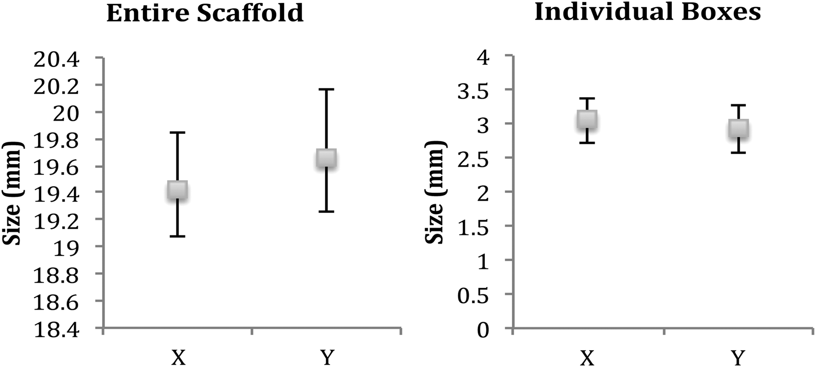
Calibration analyses of 3D bioprinted calibration “waffle” grid pattern. The x and y axes of the entire scaffold yielded an average overall size of 19.5 mm and an individual box diameter of 3.0 mm.
The printers yielded a range of 0.56–1.04% error in the axes when comparing the designed part to the actual printed part.
A bioprinted 3 mm by 3 mm construct containing hard and soft scaffolds was successfully printed on our modified Rep2X (Fig. 6). qRT-PCR analysis of alginate alone showed increased expression of collagens types 1 and 2, and aggrecan at 1 week, all three of which dropped off at the 2 weeks time point. Collagen I-based gel had an increased collagen type 1-fold change at 1 and 2 weeks (Fig. 7). Calcein AM live staining of alginate and collagen I-based hydrogels demonstrated cell survivability for each group. In the alginate-only samples, GAG concentration increased from 126.9 to 240.8 μg/mL at 1 week and to 250 μg/mL at 2 weeks (p < 0.0001). Collagen I-based hydrogel saw an increase from 210.9 to 305.9 μg/mL at 1 week to 400 μg/mL at 2 weeks (p = 0.0016; Fig. 8).

Photomicrograph of 3D bioprinted scaffold. (1 × ) in a “zig-zag” pattern with both hard (PLLA) and soft scaffolds (bioinks), concurrently printed on a sterile microscope slide and cultured.

Gene expression of the test bioinks: fold change results at 24 h, 1 and 2 weeks.

GAG assay of tested bioinks: In alginate only, GAG concentration increased from 126.9 to 240.8 μg/mL at 1 week and to 250 μg/mL at 2 weeks (p < 0.0001). Collagen I increased from 210.9 to 305.9 μg/mL at 1 week and to 400 μg/mL at 2 weeks (p = 0.0016).
Discussion
In recent years, the process of designing and fabricating new products has drastically changed with the advent of CAD and 3D printers. The efficiency of design and printing has allowed for rapid prototyping of custom objects. Despite the advancements and efforts to enhance fabrication capability of a customizable 3D bioprinted construct, hurdles still remain. Mechanical strength and integrity of the desired manufactured constructs are not completely realized. In addition, biomaterials needed for bioinks are rapidly being utilized and reformulated for use in various 3D bioprinting systems. An easy to use and inexpensive bioprinter will help usher in a better understanding of the microenvironment of the tissues and their structure, which researchers are trying to emulate with 3D bioprinting.10,11 The authors believe that, as more emphasis is being spent on materials to be used in a 3D bioprinter, more uses for these constructs will also be developed. The caveat is having a printer that is functional, cost effective, and easy to use, allowing for adoption into various research environments.
In this study, we demonstrate the ability to fabricate a customized, 3D bioprinted, biodegradable PLLA scaffold containing proliferating chondrocytes in various bioinks from a modified desktop 3D printer. Our data indicate that postextrusion, the cells are viable, proliferate, and retain their cartilaginous phenotype. When we constructed our 3D bioprinter, commercial 3D bioprinters were priced in excess of $300,000. Although highly specialized technology is extremely valuable in solving many biomedical problems, the capital cost can be prohibitive for many institutions. With our model, we have shown that widely available technology combined with innovative optimization can make these solutions accessible to almost any healthcare facility. The modification to the printer stands a proof of concept that other types of printer heads or modifications can potentially be designed, created, and attached to the printer frame, creating a process-specific machine to aid researchers in their investigations.
In addition to accessibility, our proof of concept model of tissue-engineered cartilaginous grafts can be utilized for various medical purposes. Bioprinted tissue and organ models have been increasingly investigated for their potential use in pharmaceutics, such as drug toxicology and high-throughput screening. Also, 3D bioprinted tissue-engineered constructs utilizing a patient's own cells allow for many new implantable applications to be developed.12,13 We feel that collagen is an ideal carrier for the bioink as it is a major component of various human tissues. 14 In addition, collagen has excellent biocompatibility, low antigenicity, high biodegradability, and favorable mechanical and hemostatic properties. 15 As this technology develops into mainstream use, one can imagine using it on demand in the operating room as a surgical adjunct. For example, a clinician could identify the site of damaged tissue, prepare the patient for surgery, and once the defect was precisely measured and its 3D shape clearly determined, a physician could 3D bioprint the replacement, and repair it immediately. This technology is not limited to just one piece of anatomy, the use can be for a bone graft/fracture, tracheal reconstruction, osteochondral implants, nose, or ear reconstruction. The optimization of a hard/soft 3D bioprinter allows for future research exploring the use of other polymers with varying degradation times and expanding the application of this technology to address other unmet medical challenges. In its current form, this technology is not ready for clinical use; however, the field is rapidly evolving and advancing toward this milestone.
Conclusions
In this study, a desktop 3D printer was modified to support bioinks containing proliferating cells. The printed scaffolds were fabricated for cartilage tissue engineering and for combining the versatility and strength of PLLA with a cell-seeded bioink in a 3D bioprinted environment. The scaffolds were able to support cell attachment and proliferation, whereas the bioprinted cells expressed the desired phenotypes. By introducing a widely available and inexpensive option for 3D bioprinting, we may have addressed a barrier to entry into a field for many institutions interested in this technology.
Footnotes
Disclosure Statement
No competing financial interests exist.