
Abstract
Porous scaffolds can be used to engineer three-dimensional (3D) tissues for tissue repair. Coculture of vascular endothelial cells and the cells of target tissue in porous scaffolds is promising to engineer vascularized tissue. However, it is difficult to induce regeneration of anisotropic tissues such as muscle and nerve that have well-aligned cells, blood vessels, and extracellular matrix (ECM) by using conventional porous scaffolds with homogeneous pore structures. In this study, we developed collagen porous scaffolds with parallel and concave microgrooves by using micropatterned ice template and freeze drying. Vascular endothelial cells and skeletal muscle myoblasts were cocultured on the microgrooved collagen scaffolds and control collagen scaffolds without micropattern structure. When the two types of cells were seeded at a proper ratio and concentration, the 3D microgrooved collagen scaffolds triggered spontaneous cell assembly into anisotropic muscle bundles with well-aligned tubule-like structure. Muscle cells were highly aligned in the tissue bundles, showing high expression of myosin heavy chain and incorporating the aligned tubule structure of vascular endothelial cells. Micropatterned porous scaffolds with microgrooves enabled engineering of anisotropic tissue with well-ordered tubules and could provide a platform for the study of cell assembly in micropatterned material environment.
Introduction
L
While 3D anisotropic tissues with aligned blood vessels are important for good mass transfer and tissue function, engineering such tissues remains a challenge in tissue engineering. Many approaches have been used to engineer vascularized tissues, such as use of 2D micropatterned surfaces, microfabricated conduits in hydrogel, and 3D porous scaffolds.3,9,10 Two-dimensional micropatterned surfaces can guide assembly of vascular endothelial cells, muscle cells, and mesenchymal stem cells into ordered cell sheets, but they are not suitable to engineer multilayered thick tissues.10–12 Hydrogels with microfabricated conduits could be used to obtain endothelialized network, but complicated perfusion bioreactors are required for the cell culture.13,14 Traditional 3D porous scaffolds incorporated with vascularization-promoting growth factors or cocultured with endothelial cells and cells of target tissue can be used to engineer 3D vascularized tissue, but these scaffolds cannot guide formation of anisotropic tissue with highly ordered blood vessels.15–17
In this study, we used 3D micropatterned collagen porous scaffolds with parallel and concave microgrooves to engineer multilayered anisotropic muscle tissue with highly ordered tubule structure. The 3D microgrooved structure of porous scaffolds could provide physical cues to guide controlled assembly of human umbilical vascular endothelial cells (HUVECs) and L6 rat skeletal myoblasts into ordered tissue. Collagen was used because it is the major component of ECM and can provide biological cues to regulate the cell migration, proliferation, and vessel morphogenesis of vascular endothelial cells.18,19 Microgrooved collagen scaffolds were compared with two controls, flat collagen membrane and open porous collagen scaffold, to study the effects of material microstructure on cell assembly. Ratio of HUVECs in the seeded cells and the total concentration of seeded cells in microgrooved scaffolds were also investigated for their effects on cell assembly and tissue formation.
Experimental Section
Preparation of microgrooved collagen scaffolds
Microgrooved collagen scaffolds were prepared from ice line templates and 1 wt.% type I collagen solution (solvent: 10% ethanol) as shown in Figure 1a according to our previous reports.20,21 A copper plate was wrapped with a hydrophobic polyfluoroalkoxy (PFA) film and cooled by using liquid nitrogen. A micropatterned ice line template was prepared by dispensing pure water droplets onto the PFA film-wrapped copper plate as follows. A liquid dispenser (MJET-3-CTR, Musashi Engineering Inc.) had a dispensing unit with a syringe to store pure water and a nozzle set beneath the syringe. The nozzle moved in straight lines over the cooled copper plate, ejecting water droplets that fell on the copper plate. The rapid freezing of water droplets on the plate resulted in the formation of ice lines. The size of water droplets and hence the width of ice lines were controlled by pumping pressure in the syringe and the type of nozzle. The intervals between ice lines were determined by the movement of nozzle, which was controlled by CAD programs. Ice line template was balanced at −5°C for 20 min, encircled with a silicon mold (thickness: 500 μm), filled with a cooled collagen (Nippon Meat Packers, Inc.) solution (−5°C), and covered by a flat glass plate wrapped with Saran Wrap. The construct was cooled in liquid nitrogen for 10 min and freeze dried for 24 h.

Schematic illustration of preparation of microgrooved collagen porous scaffolds for coculture.
Preparation of flat collagen membrane and open-pore collagen scaffolds
Flat collagen membrane was prepared as follows. A collagen solution was filled in a silicon frame mold (thickness: 500 μm) on a copper plate that was wrapped with Saran Wrap. The solution was flattened by covering a glass plate wrapped with Saran Wrap. The whole construct was cooled in liquid nitrogen for 10 min and freeze dried. Open-pore collagen scaffolds were prepared by freezing a collagen solution in a silicon mold (thickness: 3 mm) at −80°C, freeze drying the frozen solution, and cutting away the skin layer on scaffold surface. After freeze drying, all of the scaffolds were crosslinked (8 h, room temperature [RT]) by using 50 mM 1-ethyl-3-(3-dimethylaminopropyl)carbodiimide (EDC) and 20 mM N-hydroxysuccinimide (NHS) dissolved in 80:20 ethanol/water solvent. Scaffolds were rinsed in pure water and freeze dried again as detailed in our previous work. 22
Scanning electron microscopy
The collagen scaffolds were cut with a sharp blade, fixed with carbon tape, and coated with platinum. Coated samples were observed by using a scanning electron microscope (JSM-5610, JEOL) at an acceleration voltage of 10 kV.
Culture of myoblasts and HUVECs in scaffolds
L6 skeletal myoblasts (ATCC® CRL-1458™) were subcultured in myoblast growth medium (Dulbecco's modified Eagle's medium (D8437, Sigma-Aldrich) supplemented with 10% fetal bovine serum [FBS] and 10% horse serum). HUVECs (C2519A, Lonza) were subcultured in endothelial cell growth medium (EGM2) that contained 2% FBS and vascular endothelial growth factor (VEGF) (CC-3162, Lonza). The two types of cells were harvested through trypsinization and mixed to prepare single cell suspensions for cell seeding. The mixing ratio of L6 skeletal myoblast to HUVECs varied from 1:0 (monoculture), 3:1 to 1:1(coculture), and the total seeding concentration varied from 1 × 10⁶, 4 × 10⁶ to 6 × 10⁶ cells/mL.
All scaffolds were punched into circular disks (diameter: 10 mm, thickness: 500 μm), sterilized, and degassed with 70% ethanol under low pressure and rinsed in sterilized water before cell seeding. Each scaffold was put in one well of a 12-well plate and encircled in a glass ring (inner diameter = 10 mm, height = 10 mm) as shown in Figure 1b. Two milliliters of the culture medium (1:1 myoblast growth medium/EGM2) was added in each well and 200 μL of cell suspension was dropped onto each scaffold (number of seeded cells varied according to the total seeding concentration). After cell seeding, the cells were allowed to settle down on scaffolds for 30 min. Seeded scaffolds were carefully transferred in a 37°C incubator (5% CO2). After cell culture in the culture medium for 48 h, the glass rings were removed, followed by cell culture in 1:1 differentiation medium/EGM2 for 2 weeks. The differentiation medium was D8437 medium supplemented with 2% horse serum.
Degradation of microgrooved collagen scaffolds
The disks of microgrooved collagen scaffolds after sterilization and rinsing were placed in 15-mL tubes (one sample per tube). Five milliliters of myoblast growth medium containing serum was added to the tubes. The tubes were tightly capped and incubated in a shaking water bath incubator (Taitec Corporation., Japan) at 37°C with a shaking speed of 50 rpm for4 weeks. The medium was changed every week. The scaffold disks were washed with phosphate-buffered saline (PBS) three times followed with three times washing with pure water. After washing, the scaffold disks were freeze dried and the dry weight was measured. Four disks were used for this experiment and data were calculated as mean ± standard deviation (SD).
Immunostaining and hematoxylin and eosin staining of cocultured cells
The cell/scaffold constructs were harvested at different incubation time and fixed by immersing in 4% paraformaldehyde at RT for 20 min. Samples were rinsed in PBS, treated with 0.2% Triton X-100 (1 h, RT), and blocked in 1% bovine serum albumin (BSA) (30 min, RT) on a rocker. 23 Primary antibody was diluted in 1% BSA and incubated with the samples overnight at 4°C. The samples were rinsed in PBS and incubated with diluted secondary antibody (1 h, RT). The primary antibody added to the samples was monoclonal mouse anti-human CD31 antibody (Clone JC70A, Dako) (1:40 dilution) or MF20 (Developmental Studies Hybridoma Bank) (1:300 dilution). The secondary antibody was goat anti-mouse IgG secondary antibody conjugated with Alexa Fluor 594 or Alexa Fluor 488 (Life Technologies) (1:500 dilution). After the immunostaining of hCD31 or myosin heavy chain (MHC), F-actin was stained by using Alexa Fluor 488 Phalloidin or Alexa Fluor 594 Phalloidin (Thermo Fisher Scientific). Cell nuclei were stained with Cellstain-DAPI Solution (Dojindo) (10 min, RT). Samples were rinsed in PBS and put in PBS during imaging through a fluorescence microscope (Olympus) or a confocal microscope (Zeiss LSM 510 Meta). For hematoxylin and eosin (HE) staining, samples cultured for 2 weeks were fixated with 10% neutral buffered formalin for 2 days, followed by dehydration with ethanol of increasing concentrations and permeation with lemonsol A and paraffin. Samples were cut in 8 μm sections and the cross-sections were stained using routine HE staining method. Four samples were used for the staining procedures.
Measurement of cell assembly
After culture for different time periods, the cell/scaffold constructs were immunostained and their images were taken by using a fluorescent microscope. For each group of sample, images were taken from at least three samples. The images were imported in ImageJ software to measure the width of cell bands in the microgrooves and the length and width of the tubule-like structure. The measured values were calculated as mean ± SD. For statistical analysis, student-t test was used to compare two groups of data.
Results
Fabrication of microgrooved collagen scaffolds
Three-dimensional microgrooved collagen scaffolds were prepared by using liquid dispensing and freeze drying. The hydrophobic PFA film resulted in the formation of the semicylindrical shape of ice lines in the micropatterned template. The size of water droplets and hence the width of ice lines on the copper plate were controlled by the air pressure that pumped water out of the nozzle (0.001 MPa) and size of nozzle (34 G). The interval between neighboring ice lines was set as 200 μm in the CAD program to control the interval of ice lines. The micropatterned ice line templates were covered by collagen solution to prepare microgrooved collagen porous scaffolds. The collagen solution at −5°C remained in liquid state by the use of 10% ethanol as solvent, which enabled flow of collagen solution into the gap of adjacent ice lines. Flat collagen membranes (Flat) and open porous collagen scaffolds (Open-pore) without microgrooves were also prepared for cell culture as controls. All of the scaffolds were crosslinked and freeze dried.
Microstructure and degradation of collagen scaffolds
The three types of collagen scaffolds with different porous structures were prepared for cell culture. Microgrooved collagen scaffolds with average microgroove width of 200 μm were used for cell culture because the scaffolds with 200 μm microgrooves enabled more ordered muscle tissue formation than did the scaffolds with narrower (120 μm) or wider microgrooves (380 μm). 24 The microgrooved scaffolds had parallel microgrooves with a width of 205 ± 12 μm and a height of 103 ± 8 μm, which mirrored the micropatterned ice line templates used to prepare the scaffolds (Fig. 2a–c). Flat collagen scaffolds had a flat and dense skin layer, whose surface pores were very small (Fig. 2d). Open-pore collagen scaffolds had a random porous structure (Fig. 2e). Degradation of the microgrooved collagen scaffolds were investigated by incubation in cell culture medium at 37°C for 4 w. Dry weight of the microgrooved collagen scaffolds decreased to 95 ± 2% of that of the original dry weight.
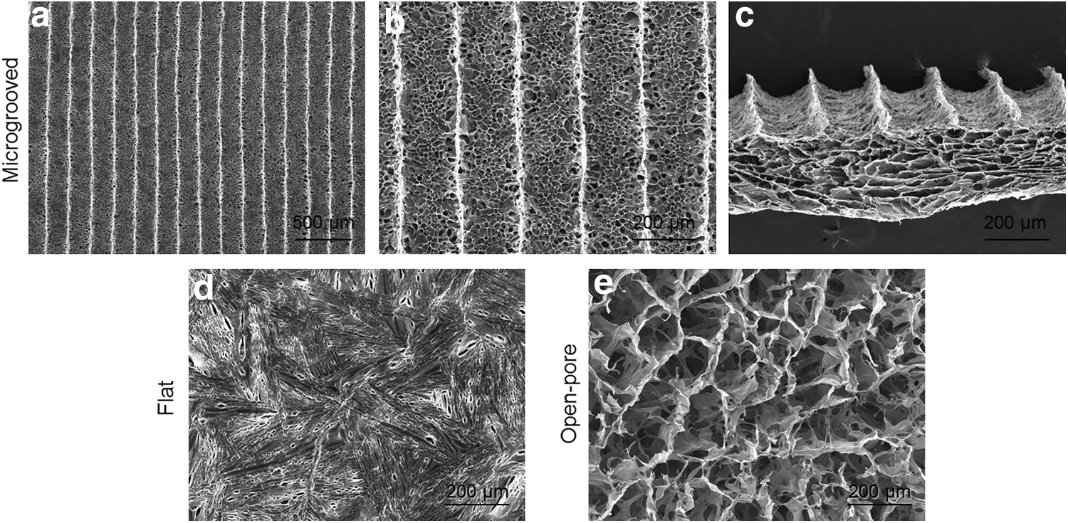
The microstructure of
Cell assembly in collagen scaffolds
Assembly of myoblasts and HUVECs was examined after coculturing the two types of cells in the three types of scaffolds for 12, 24, or 48 h (Fig. 3). After 12 h incubation, myoblasts and HUVECs adhered in the three types of collagen scaffolds. Cells randomly adhered and distributed in Flat and Open-pore scaffolds, but distributed predominantly in the microgrooves of microgrooved collagen scaffolds. After 24 h incubation, HUVECs aggregated into individual cellular islands that were surrounded by myoblasts. After 48 h incubation, myoblast flakes tended to retract and the HUVEC islands remained in Flat and Open-pore scaffolds. The myoblast retraction in Flat scaffolds was more evident than that in Open-pore scaffolds as the edge of cell flakes retracted and curled up. On the other hand, myoblasts in the microgrooved scaffolds retracted toward the central axis of microgrooves and formed cell bands in which HUVEC islands fused into tubule-like structure along the microgrooves. Width of cell bands in microgrooves decreased within 48 h postcell seeding and became stable after 48 h (Supplementary Fig. S1; Supplementary Data are available online at

The assembly of myoblasts and HUVECs in the Flat, Open-pore, and microgrooved collagen scaffolds. The ratio of myoblasts to HUVECs seeded in the scaffolds was 3:1
Effect of cell ratio and seeding concentration on cell assembly
Formation of tubule-like structure and ordered cell bundles were dependent on ratio of the two cell types and cell seeding concentration. Effects of seeding ratio and total seeding concentration on cell assembly are shown in Figure 4. When total cell seeding concentration was fixed at 4 × 10⁶ cells/mL, both monoculture (ratio of myoblasts to HUVECs was 1:0) and cocultures (ratio of myoblasts to HUVECs was 3:1 or 1:1) in microgrooved collagen scaffolds resulted in the formation of well-aligned muscle bundle tissue. However, ratio of myoblasts and HUVECs affected the formation of tubule-like structure (Fig. 4a, Supplementary Movies S1 and S2). A low ratio of HUVECs in coculture (3:1) resulted in the formation of intermittent tubule-like structure from HUVECs and some small HUVEC aggregates that did not fuse into the tubule-like structure. A high ratio of HUVECs in coculture (1:1) resulted in the formation of continuous tubule-like structure from HUVECs and a majority of HUVECs were fused into tubule-like structure. Assembly of myoblasts and HUVECs were also affected by total cell seeding concentrations (Fig. 4b). With a fixed ratio of myoblasts and HUVECs at 1:1, the coculture from an intermediate seeding concentration (4 × 10⁶ cells/mL) formed parallel muscle bundle tissue with aligned HUVEC tubules. A low cell seeding concentration (1 × 10⁶ cells/mL) resulted in cellular aggregates in the microgrooved scaffolds, whereas a high seeding concentration (6 × 10⁶ cells/mL) resulted in the formation of a HUVEC sheet lying on parallel muscle bundle tissue.

The assembly of myoblasts and HUVECs seeded at
Maturation of anisotropic muscle bundle with aligned tubule structure
After coculture for 2 weeks, assembly of the cells became more evident and matured (Fig. 5). Confocal microscopy images of the cells in the microgrooved scaffolds showed that HUVECs assembled into tubule-like structure that was incorporated within the aligned muscle bundle tissue. While cell seeding at a low ratio of HUVECs (fibroblasts:HUVECs = 3:1) resulted in intermittent tubule segments, cell seeding at a high ratio of HUVECs (fibroblasts:HUVECs = 1:1) resulted in continuous tubules from HUVECs (Fig. 5a). The length of tubules formed at a 1:1 seeding ratio was significantly greater than that formed at 3:1 seeding ratio, whereas the width of tubules showed no significant difference (Fig. 5b). HE staining of the cells cultured in the microgrooved scaffolds showed that seeding at high ratio of HUVECs (1:1) favored formation of tubule-like structure, whereas seeding at low ratio of HUVECs (3:1) resulted in much less tubule-like structure formation (Supplementary Fig. S2). Myoblasts fused into muscle bundle tissue that showed a high expression level of MHC proteins after 2-week culture (Fig. 5c,d). In addition, the muscle cells within the bundles were highly aligned as shown by the unidirectional MHC and F-actin. The central axis portion of a muscle bundle was devoid of MHC staining, which was common in cocultures formed at 1:1 seeding ratio, but less frequent in cocultures formed at 3:1 seeding ratio.

The formation of vascularized and well-ordered muscle bundle tissue in the microgrooved scaffolds after 2-week culture.
Discussion
Based on the results we proposed a mechanism for the assembly of myoblasts and HUVECs in the microgrooved scaffolds. When a homogeneous mixture of myoblasts and HUVECs was seeded in the scaffolds, the cells distributed and attached homogeneously in the scaffolds. If the seeding concentration was high enough, myoblasts could contact with each other and retract toward the central axis of microgrooves to form cell bundle tissue (Fig. 3e). During cell bundle formation, HUVEC aggregated into islands which might be because HUVECs tended to exclude the surrounding myoblasts or the ECM synthesized by myoblasts. In normal tissues, vascular endothelial cells are polarized cells that have an apical surface that excludes adhesion to ECM proteins and a basal surface that adheres to the underlying basement membrane proteins. 25 This cell polarity can make vascular endothelial cells to assemble into capillary-like networks when they are cultured within ECM matrix such as collagen gels. 26 Endothelial cells can also form individual cellular networks or aggregates after being seeded in myoblast cell sheets, which indicates that polarized endothelial cells in coculture can migrate together to minimize contact with neighboring myoblasts.5,27 Retraction of a cell band into a narrower cell bundle should make HUVEC islands of the cell band approach and fuse into tubular-like structure. The lack of MHC immunostaining in the central axis of cell bundles (Fig. 5c) and the HE staining of coculture (Supplementary Fig. S2c) confirmed the formation of tubular-like structure in cell bundle tissue. Prolonged culture of the assembled cells in the microgrooved scaffolds led to maturation of muscle tissue as shown by high expression levels of anisotropic MHC.
Microstructure of the scaffolds affected the assembly of myoblasts and HUVECs. While myoblasts in microgrooves retracted to form cell bundles, myoblasts on Flat collagen membranes or in Open-pore collagen scaffolds could retract in random directions. This could cause the curling up of cell sheet on collagen membrane or cell aggregation on the pore walls of Open-pore scaffolds and encapsulation of HUVEC islands in the aggregates (Fig. 3a,b; 24–48 h). In contrast, microgrooved collagen scaffolds induced the assembly of myoblasts and HUVECs into tubule-like structure and well-ordered muscle bundle tissue.
Apart from the scaffold microarchitecture, the seeding ratio of HUVECs and total cell seeding concentration also affected assembly of the two cell types. All seeding ratio of myoblasts to HUVECs (1:0, 3:1, and 1:1) enabled the formation of muscle bundle tissue. A low ratio of HUVECs in the coculture (3:1) resulted in the formation of intermittent tubule-like structure from HUVECs. The reason might be that less HUVECs in the coculture had smaller frequency of encountering each other and fusing together, which has been reported to cause formation of short capillary segments from HUVECs. 27 However, a high ratio of HUVECs in the coculture could enhance the frequency of HUVECs encountering each other to form continuous tubule-like structure. The results were in agreement with previous studies that have reported that coculture of human muscle progenitor cells and HUVECs, which contains 50% HUVECs, has improved network formation within muscle fibers.27,28
A proper seeding concentration was required to form muscle bundle tissue with HUVEC tubules. A low seeding concentration (1 × 10⁶ cells/mL) resulted in formation of cellular spheroids rather than cell bundles in the scaffolds, which was in agreement with previous studies.24,29 Cells seeded at a high concentration (6 × 10⁶ cells/mL) formed a layer of HUVEC covering the muscle bundle tissue, which was similar to a previous study, where HUVECs seeded at a high concentration with myoblasts can migrate onto myoblast sheet. 23 When cells were seeded at high concentration, HUVECs in one microgroove were likely to encounter and adhere to those from neighboring microgrooves, which could lead to the formation of a HUVEC layer on top of myoblast bundles.
Coculture of myoblasts with HUVECs in the microgrooved collagen scaffolds resulted in the unique cell assembly into multilayered muscle bundle tissue with well-aligned tubular structure, which mimicked the anisotropic tissues such as skeletal muscle that have well-aligned blood vessels. Coculture of vascular endothelial cells with target tissue cells in conventional biomaterials has been used to engineer vascularized tissues. Endothelial cells have been cocultured with muscle cells or fibroblasts in hydrogel or porous scaffolds to engineer vascularized tissue.30–33 However, these materials lack the topography that guides the formation of anisotropic tissues. HUVECs cultured within myoblast sheets can assemble into capillary networks, but these networks are usually random. 34 Recently, thermoresponsive micropatterns have been used to generate anisotropic myoblast sheets to guide the assembly of endothelial cells, but this method requires tedious multiple harvesting and stacking of cell sheets. 5
Microgrooved substrates can be used to generate anisotropic tissues by using contact guidance. Previous studies usually use substrates that have shallow microgrooves with height of several micrometers, which results in the formation of a thin layer of aligned myotubes.35,36 PLGA nanoribbons, with groove widths of 50 or 100 μm and height of about 4 μm, have been used to generate layers of aligned myoblasts and these myoblast layers can be stacked to get bilayered myoblasts. 37 However, these substrates cannot be used to generate multilayered anisotropic tissue and the multiple alignment and stacking of cell sheets are difficult to manipulate. In this study, micropatterned collagen scaffolds with large, concave microgrooves (200 μm) stimulated the spontaneous assembly of cells to form multilayered anisotropic muscle tissue. The forming tissue in the microgrooved scaffold can be rolled up into a cylinder with parallel muscle bundles along its central axis. Parallel stacking of the scaffolds with forming tissue can also be used for scaling up of the engineered tissues.
The scaffolds seeded with HUVECs and myoblasts maintained their original microstructures during cell culture, which could be observed from the HE staining of tissue/scaffold constructs (Supplementary Fig. S2). This could be explained by the high crosslinking degree of collagen scaffolds as achieved by using a crosslinking solution of 50 mM EDC and 20 mM NHS. Collagen scaffolds crosslinked in this way were immersed in a culture medium at 37°C for 4 weeks and the dry weight of the scaffolds only showed slight decrease. Our previous studies also showed that collagen scaffolds crosslinked in the same condition did not degrade and maintained their original microstructures after 4 weeks of cell culture in vitro. 24 These results indicated the slow in vitro degradation and robustness of the crosslinked collagen scaffolds during cell culture.
Formation of endothelial tubules by cell assembly in this study should be different from vascular network development during vasculogenesis and angiogenesis. During the vascular development, the angioblasts within the mesoderm differentiate and aggregate into cords. The endothelial cells in the cords reorganize into tubules with lumens, forming vessels of different sizes. Vascular endothelial growth factor and specific cell adhesion molecules, such as VE-cadherin, are important factors that affect cell differentiation and vascular development.38,39 In this study, cell–cell interaction of the cocultured cells and microgrooves of the microgrooved collagen scaffolds resulted in the formation of parallel endothelial tubules. These tubules with a diameter of 40–50 μm were assembled from multiple endothelial cells bridging each other on the microgroove walls. The endothelial tubules were formed within the first week of culture and were stable during the second week of culture. However, the long-term stability of endothelial tubules formed in this way remains to be investigated by using prolonged cell culture or implantation into animal bodies.
Conclusion
In summary, microgrooved collagen scaffolds with parallel, concave microgrooves were fabricated for coculture of skeletal myoblasts and vascular endothelial cells. Myoblasts and HUVECs in the microgrooved scaffolds spontaneously assembled into aligned tubule-like structure and anisotropic multilayered muscle bundle, mimicking the structure of anisotropic tissues with aligned blood vessels. Scaffold microstructure, seeding ratio of HUVECs and the total seeding concentration of myoblasts/HUVECs affected the cell assembly during cell culture. Culturing different types of cells in the microgrooved collagen scaffolds could be a useful method for engineering of anisotropic vascularized tissue and for investigation of cell–cell interaction in a 3D micropatterned material environment.
Footnotes
Acknowledgments
This work was supported by the World Premier International Research Center Initiative (WPI) on Materials Nanoarchitectonics from the Ministry of Education, Culture, Sports, Science, and Technology, Japan and JSPS KAKENHI (Grant Nos. 15H03027 and 15K12548).
Disclosure Statement
No competing financial interests exist.
References
Supplementary Material
Please find the following supplemental material available below.
For Open Access articles published under a Creative Commons License, all supplemental material carries the same license as the article it is associated with.
For non-Open Access articles published, all supplemental material carries a non-exclusive license, and permission requests for re-use of supplemental material or any part of supplemental material shall be sent directly to the copyright owner as specified in the copyright notice associated with the article.