
Abstract
The success of cardiovascular tissue engineering (TE) strategies largely depends on the mechanical environment in which cells develop a neotissue through growth and remodeling processes. This mechanical environment is defined by the local scaffold architecture to which cells adhere, that is, the microenvironment, and by external mechanical cues to which cells respond, that is, hemodynamic loading. The hemodynamic environment of early developing blood vessels consists of both shear stress (due to blood flow) and circumferential stretch (due to blood pressure). Experimental platforms that recapitulate this mechanical environment in a controlled and tunable manner are thus critical for investigating cardiovascular TE. In traditional perfusion bioreactors, however, shear stress and stretch are coupled, hampering a clear delineation of their effects on cell and tissue response. In this study, we uniquely designed a bioreactor that independently combines these two types of mechanical cues in eight parallel vascular grafts. The system is computationally and experimentally validated, through finite element analysis and culture of tissue constructs, respectively, to distinguish various levels of shear stress (up to 5 Pa) and cyclic stretch (up to 1.10). To illustrate the usefulness of the system, we investigated the relative contribution of cyclic stretch (1.05 at 0.5 Hz) and shear stress (1 Pa) to tissue development. Both types of hemodynamic loading contributed to cell alignment, but the contribution of shear stress overruled stretch-induced cell proliferation and matrix (i.e., collagen and glycosaminoglycan) production. At a macroscopic level, cyclic stretching led to the most linear stress–stretch response, which was not related to the presence of shear stress. In conclusion, we have developed a bioreactor that is particularly suited to further unravel the interplay between hemodynamics and in situ TE processes. Using the new system, this work highlights the importance of hemodynamic loading to the study of developing vascular tissues.
Impact Statement
Hemodynamic loading plays an important role in the formation, organization, and repair of cardiovascular tissues. Based on this notion, bioreactors that recapitulate the hemodynamic environment are critical to investigate cardiovascular tissue engineering. In this study, we successfully designed a bioreactor to independently apply physiological levels of shear stress and cyclic stretch in vascular constructs. This study contributes to a better understanding of the individual and combined roles of hemodynamic loads on cell-induced growth and remodeling.
Introduction
T
The mechanical environment to which cells adapt is defined by local physical characteristics, such as scaffold architecture, mechanical properties, and degradation rate, 4 and by hemodynamic loading, such as flow-induced shear stresses and pressure-induced stretch. Recapitulating this mechanical environment in a controlled and tunable manner, for example through the use of bioreactors, is therefore essential for investigating and improving cardiovascular TE.
As a result of pulsatile blood pressure and blood flow, the arterial vascular wall is continuously subjected to three types of stress: axial wall shear stress (WSS, in the range of 1–5 Pa), circumferential stress (100–150 kPa, resulting in stretches of around 1.10–1.15), and axial stress (with associated prestretches of 1.5–1.7). 6 The impact of such multiaxial biomechanical cues on tissue growth, remodeling, and homeostasis in tissue-engineered vascular grafts (TEVGs) is widely recognized, and has resulted in the development of several bioreactor systems that mimic parts of the hemodynamic environment in TEVGs. These bioreactors are used either to precondition tubular tissues to enhance their mechanical and biological properties 7 or to gain more fundamental insight in the interaction between cells, their environment, and external mechanical cues. 8
Using various types of bioreactors, it has been shown that fluid shear stress and multiaxial stretch separately affect cellular behavior, such as proliferation, differentiation, orientation, and matrix synthesis.9,10 However, due to the sparsity of methods to dissect and combine shear stress and stretch in three-dimensional (3D) constructs, new insights on the subject are currently mostly restricted to two-dimensional (2D) platforms.
In 3D platforms, shear stress and stretch are typically studied separately. For example, Smits et al. 11 designed a bioreactor that is capable of applying WSS to 3D synthetic scaffolds in the physiological target range (0–8 Pa). However, this system is not able to sustain long-term tissue growth in combination with stretch. Huang et al. 7 developed an in vitro platform to apply cyclic stretch in the axial (1.10) and circumferential (1.02) direction of TEVGs. Although their system allows investigation into the impact of long-term biaxial stretching, it does not enable simultaneous perfusion, hindering comparison to in vivo biomechanical environments. Niklason et al. 12 was one of the first to culture tissue-engineered vessels in a perfusion system. Although these systems are widely used nowadays, achieving individual control of the different mechanical stimuli remains a key technological challenge.
Fluid shear stress scales with the cube root of the vessel diameter (Supplementary Equations 1 and 2; Supplementary Data are available online at
The aim of this study was to design and validate a mesofluidics-based in vitro platform that allows independent control of circumferential stretch and axial WSS in a 3D tubular scaffold. To this end, we developed a bioreactor system where the hemodynamic conditions were thoroughly validated, both computationally and experimentally. To exemplify the usefulness of the system for vascular TE, we investigated the isolated and combined effects of cyclic stretch (∼1.05 at 0.5 Hz) and WSS (1 Pa) on ECM production and mechanical performance of human vena saphena-derived cells (HVSCs) in 3D electrospun polycaprolactone bisurea (PCL-BU) scaffolds.
Materials and Methods
Design of in vitro test platform
Culture chamber design
We designed a bioreactor to be able to independently apply predefined amounts of circumferential stretch and WSS during the in vitro growth of up to eight tubular scaffolds (Table 1; Fig. 1A). The tubular scaffold, centered in a glass tube, can be pressurized from the inside, generating circumferential stretch, and perfused through the annular channel between the scaffold and glass wall, generating WSS (Fig. 1B). The circumferential stretch,
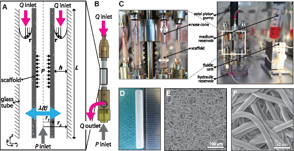
The WSS,
In this study, the pressure gradient in the axial (z) direction is assumed to be uniform between the flow inlet and flow outlet, given by the following equation:
with
Computationally driven channel dimensions
To rationally design the culture chamber, it is necessary to investigate and account for the effect of changing channel dimensions, as a result of circumferential stretch, on the WSS distribution under pressure-driven flow conditions. To this end, we performed numerical simulations of the annular flow channel using a computational fluid dynamic model. In this model, the fluid flow is governed by the unsteady Navier-Stokes equations for Newtonian and incompressible fluids. The simulations were performed using an in-house finite element package (TFEM, 16 ). Since the annular flow channel has a rotational symmetry with respect to its axial axis, pressure and velocity components can be assumed to be independent of the circumferential direction, and all circumferential velocity components can be assumed to be zero. Therefore, in the simulation, the annular flow channel was simplified to a 2D axisymmetric problem, represented by a rectangular mesh consisting of biquadratic quadrilateral Taylor-Hood elements (100 elements in axial (z) direction and 30 elements in radial (r) direction, see Supplementary Fig. S1 and Table S1). To generate low WSS (1.5 Pa) and high WSS (4.5 Pa), a constant pressure between 95 and 280 Pa was prescribed as a boundary condition at the inlet of the channel (according to Eq. (2)), and a zero-pressure boundary condition was defined at the end of the channel. To simulate the stretch, a time-dependent displacement was prescribed for the scaffold surface using a sinusoidal waveform with a frequency of 1 Hz and an amplitude in the range of 5–10% of the initial scaffold radius (i.e., 1.05–1.10 stretch). The velocity of the moving scaffold wall was used as boundary condition for the fluid. At the fixed wall of the inner glass, a no-slip condition, that is, zero velocity, was defined. The simulation allows us to compute the velocity profiles and WSS distributions at the scaffold surface, based on which we tuned the graft length L and channel height h to achieve homogenized loads within the limits of the available pumps and experimental setup (Fig. 1A).
Flow control
The culture chamber is incorporated into a flow loop to generate continuous unidirectional flow through the annular channel between the scaffold and the glass wall (Fig. 1C). The flow is controlled by an Ibidi pressure pump (Ibidi GmbH, Martinsried, Germany; 200 mbar capacity). The flow magnitude can be derived from the changing medium levels in the medium reservoirs and manually tuned by adjusting the pump pressure.
Stretch control
Cyclic circumferential stretching on the scaffolds can be applied, simultaneous to the perfusion. To this end, the tubular scaffolds (3 mm inner diameter and 200 μm wall thickness) are mounted around silicone tubing (2.8 mm outer diameter and 400 μm wall thickness), which is filled with water. By compressing the water in the silicone tube using a linear actuator (M-235.5DD; Physik Instrumente, Karlsruhe, Germany), circumferential stretch is generated on the scaffolds. The linear actuator pressurizes a hydraulic reservoir through an impermeable bellows to which eight culture chambers can be connected (Fig. 1C), ensuring equal loading conditions between samples. Silicone is known for its outstanding fatigue properties, making the system suitable for long-term (i.e., weeks) cyclic stretching regimes. In addition, the use of silicone makes it possible to apply stretch to porous (i.e., leaking) materials. To monitor the stretch during culture, time-lapse photographs of the scaffolds are captured with a high-speed camera at a frequency of 30 Hz for 6 s (i.e., three stretch cycles). The minimum and maximum outer diameter of the scaffolds were measured using a custom Matlab script (Matlab R2017; The Mathworks, Natick, MA) to calculate maximum stretches according to Equation (1).
Experimental validation
Scaffold preparation
Tubular PCL-BU (SyMO-Chem, Eindhoven, The Netherlands) scaffolds were produced using electrospinning from 15% (w/w) chloroform (Sigma; 372978) polymer solutions. The polymer solutions were electrospun at room temperature and 30% relative humidity using a flow rate of 40 μL/min, a distance to the rotating cylindrical target (Ø 3 mm, 500 rpm) of 16 cm, and an applied voltage of 16 kV on the electrospinning nozzle and −1 kV on the target. The resulting scaffolds (Fig. 1D–F), with an initial stiffness of 2.6 ± 0.7 MPa and 3.1 ± 0.6 MPa in circumferential and axial direction, respectively, were dried for 24 h at room temperature under low pressure (1 × 10⁻¹ mbar) to remove any solvent. After removal from the target, the tubular scaffolds with length of ∼25 mm were placed over the silicone tubing and mounted in the bioreactor using suture material at both ends of the scaffold, resulting in an effective scaffold length of 20 mm. Before seeding, the scaffolds were sterilized by UV exposure with wavelength of 253.7 nm (30 min/side), prewetted with water, and incubated with medium overnight (37°C).
Tissue culture
HVSCs were harvested from pieces of saphenous vein, leftover after coronary by-pass surgery, according to the Dutch guidelines for secondary use of materials. Passage-5 HVSCs were expanded in a culture medium (Dulbecco's modified Eagle's medium (DMEM) Advanced [Gibco] with 10% fetal bovine serum [Greiner, Alphen aan den Rijn, The Netherlands], 1% GlutaMax [Gibco; ref 35050], and 1% Penicillin Streptomycin [Lonza, Basel, Switzerland; DE17-602E]). The prewetted scaffolds were seeded with HVSCs using fibrin as a cell carrier.
17
In short, a suspension of bovine fibrinogen (10 mg/mL, F8630; Sigma), bovine thrombin (10 IU/mL, T4648; Sigma), and HVSCs (10 × 106 cells/mL) was carefully dripped onto the prewetted scaffold until the suspension was absorbed by the entire scaffold. Next, fibrin was allowed to polymerize in the scaffolds for 60 min (37°C, 5% CO2). Subsequently, the culture chamber was mounted on the stretch pump and connected to the flow loop. The medium reservoirs were filled with 50 mL of culture medium supplemented with 0.25 mg/mL
Experimental design
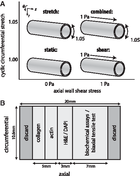
As a proof of principle, the cell-seeded electrospun scaffolds were exposed to four types of mechanical loading for 10 days: static culture (n = 6), perfusion at predefined WSS only (n = 6, 1 Pa WSS as a result of 5.3 kPa applied pressure), circumferential stretching only (n = 4, ∼1.05 stretch at 0.5 Hz frequency), and circumferential stretching and perfusion combined (n = 4) (Fig. 2A). After 10 days of culture, the constructs were analyzed on their mechanical properties and matrix formation (Fig. 2B).
Construct analysis
Histology
At day 10, the constructs were fixed in 3.7% formaldehyde (3 × 5 min) and washed in phosphate-buffered saline (PBS) (3 × 5 min). After fixing, cryosections (5 μm) were stained with 4′,6-diamidino-2-phenylindole (DAPI) to assess cell distribution, and with hematoxylin and eosin (H&E) to assess overall matrix formation. DAPI-stained cryosections were visualized (λex = 405 nm, λem = 460 nm) using an inverted epifluorescence microscope (Zeiss Axiovert 200M, 1 pixel = 0.52 μm with a 20 × /0.5NA Plan-Neofluar lens). H&E-stained cryosections were visualized using bright-field microscopy (Zeiss Axio Observer Z1, 1 pixel = 0.27 μm with a 40 × /1.3NA Plan-Apochromat lens).
Cell and matrix organization
To visualize the engineered tissue architecture and cellular distribution in the cultured constructs, the formalin-fixed samples were labeled with CNA35-OG488
18
and DAPI. A confocal laser scanning microscope (Leica TCS SP5X, 1 pixel = 1.52 μm or 0.39 μm with a 10 × /0.4 or 40 × /1.1 HCX PL Apo CS lens, respectively) was used to assess collagen architecture (λex = 488 nm, λem = 525 nm) and locate cell nuclei. By exploiting the autofluorescence properties of PCL-BU (λex = 405 nm, λem = 460 nm), the scaffold fibers could be detected without fluorescence labeling. Next, to visualize the associated cellular organization around the nuclei, samples were labeled with phalloidin-Atto 488 (1:200; Sigma, λex = 488 nm, λem = 525 nm) and propidium iodide (λex = 543 nm, λem = 617 nm), respectively. Based on the Hessian matrix, the principal direction in each pixel of the actin images was calculated and binned into a histogram (nbin = 45 between 0 rad and
Cell and matrix composition
DNA, glycosaminoglycan (GAG), and hydroxyproline (HYP) content were quantified as indicators of tissue formation during culture. Before digestion, the samples were lyophilized and weighed to determine the total tissue dry mass (i.e., scaffold mass + engineered matrix mass). Subsequently, samples were transferred to Nalgene® cryogenic vials (Sigma; V5007) containing Ø 3 mm beads, frozen in liquid nitrogen, and disrupted with a microdismembrator (Sartorius, Goettingen, Germany) twice for 30 s at 3000 rpm. After disruption, a papain-enriched digestion buffer (100 mM phosphate buffer [pH = 6.5], 5 mM
Using 10 μL of the supernatant, genomic DNA was quantified with a Qubit dsDNA BR assay kit (Life Technologies; Q32853) and a Qubit® 2.0 Fluorometer (Life Technologies) according to the manufacturer's protocol. GAG amounts were determined with an adapted dimethyl methylene blue (DMMB) assay, 19 with shark chondroitin sulfate (Sigma; C4348) as a standard. In brief, 40 μL of the supernatant or prepared standard was pipetted in duplicate into a 96-well plate, followed by 150 μL of the prepared DMMB solution. Absorbance was measured at 540 nm using a microplate reader (Synergy HTX; Biotek). HYP, a major component of mature collagen protein, was used as a measure for collagen. Digested samples were hydrolyzed using 16 M sodium hydroxide (Merck; B1438798) and HYP content was quantified with a Chloramin-T assay, 20 using trans-4-hydroxyproline as a standard (Sigma; H5534). Quantities were normalized to total tissue dry mass and to DNA content to assess overall tissue formation and tissue formation per cell, respectively.
Mechanical characterization
Biaxial tests in PBS at 37°C were performed to measure the mechanical properties of the constructs (CellScale Biomaterial Testing, Waterloo, Canada; equipped with a 1500 mN load cell). Using a scalpel, the tubular constructs were longitudinally opened and 7 × 7 mm2 samples were cut. The construct thickness was measured at three locations with a digital microscope (Keyence VHX-500FE). Before mounting the sample, graphite particles were sprayed onto the surface to facilitate optical strain analysis using digital image correlation. To measure the moduli in the circumferential and longitudinal directions, we aligned the sample's circumferential and longitudinal directions to the stretching direction of the tensile tester. After a preconditioning period of 10 cycles of 10% uniaxial strain in both directions, the samples were equibiaxially stretched at a 100% min−1 strain rate until failure. The Cauchy stress was derived from the force and displacement measurements, assuming incompressibility and plane-stress conditions. The elastic moduli were computed as the slopes at 5% and 10% strain.
Statistical analysis
Statistics were performed with IBM SPSS Statistics 22. Data were tested for normality (Shapiro-Wilk test) and equal variances (Levene's test). Depending on the normality of the data, differences between the experimental groups were detected using one-way analysis of variance with subsequent Tukey's post hoc test (assuming equal variances) or Dunnett's T3 post hoc test (unequal variances), or a nonparametric Kruskal-Wallis test. Statistical significance was assumed for p < 0.05.
Results
Computationally driven chamber design
Disturbances to the flow, therewith the WSS, are dependent on the changing dimensions of the annular flow channel, with the most stable flow for shorter scaffold lengths and larger channel heights. In practice, however, a sufficiently long scaffold is necessary to obtain enough material for analysis, and the range of possible channel heights is limited by the limits of the pressure that can be applied by the pump. A trade-off between these variables is therefore required. To find an optimal bioreactor design and working conditions, we performed numerical simulations of the annular flow channel using a computational fluid dynamics model. We found that a trade-off can be made by combining a 20 mm sample length with a 0.6 mm channel height (Fig. 3A, B).

To assess the effect of scaffold stretch and WSS using these channel dimensions, we first examined the spatial WSS profiles on the scaffold surface with the largest disturbances that can be expected (Fig. 3C). Under these extreme conditions, high WSS (3.6–4.3 Pa) can be easily distinguished from low WSS (1.2–1.4 Pa) under both stretch regimes (λ = 1.05 and 1.10). Furthermore, we also examined the temporal WSS profiles at the center of the graft (where the largest temporal variations are expected), and the profiles show similar variations (Fig. 3D). Thus, these chamber dimensions are ideally suited for systematically distinguishing different types of loading (i.e., shear stress and cyclic stretch) without inducing flow disturbances.
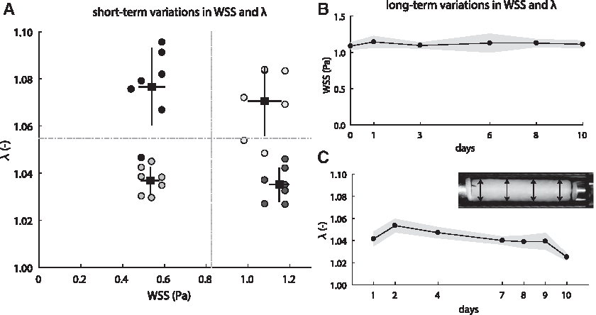
To further test the ability to experimentally apply scaffold stretch and WSS using the computationally driven chamber design, we performed a validation experiment in which seven culture chambers were simultaneously loaded under four distinct system settings (i.e., two shear stress regimes and two stretch regimes). Under each system setting, the resulting stretch and WSS were measured in each culture chamber. Although the variations in stretch become larger with higher stretches, as expected, the four different types of loading can easily be distinguished from each other (Fig. 4A). Thus, the bioreactor allows to experimentally distinguish between different loading conditions.
Flow and stretch control
Assuming a constant medium viscosity (μ = 0.7 × 10⁻³ Pa · s at 37°C), the WSS at the scaffold scales linearly with the flow rate through the culture chamber [Eqs. (2) and (3)]. Using r1 = 1.7 mm and r2 = 2.3 mm, we obtain the following:
Tissue analysis
Cells
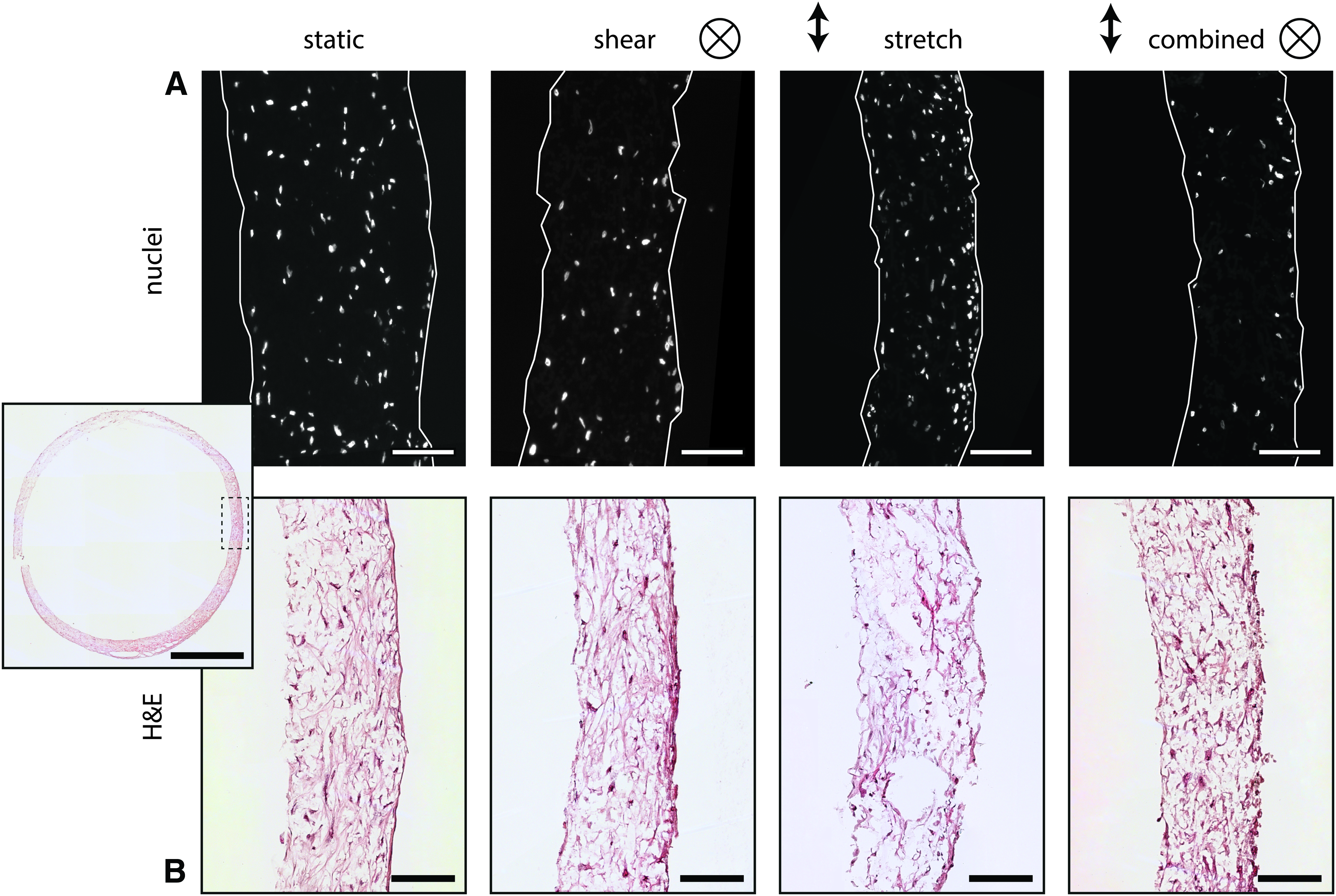
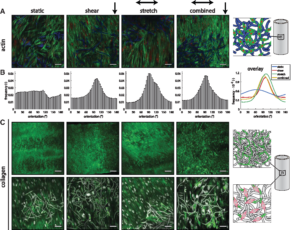
The DAPI staining (Fig. 5A) demonstrated that complete cell infiltration is achieved under all loading conditions. To better assess the in-plane organization of cells, we imaged the samples with confocal microscopy. Actin fibers were detected as a thin layer outside the scaffold and between scaffold fibers (Fig. 6A). While no preferential orientation in actin fiber direction can be observed in statically cultured samples, a clear preferred orientation in the axial direction is observed in cyclically stretched samples (Fig. 6B). This phenomenon is also observed in samples exposed to shear stress (with and without stretch).
Tissue
The H&E staining of the samples at day 10 (Fig. 5B) indicated that matrix was formed under all conditions throughout the scaffold. However, the scaffold fibers are not visible due to the xylene washing steps, resulting in apparent gaps in the tissue. To quantitatively assess the tissue formation under different hemodynamic conditions, we biochemically quantified the amount of collagen and GAG. HYP, a matrix component that helps to stabilize the collagen molecule, could not be detected after 10 days of culture. In line with this finding, with confocal microscopy, collagen bundles could only be detected in cyclically stretched or statically cultured samples (Fig. 6C). In the presence of shear stress, the green fluorescent signal was detected intracellularly, suggesting a diffusion of the collagen marker into the cell cytoplasm. In contrast, GAG, another matrix component produced by HVSCs, was sufficiently present to be detected. The amount of GAGs in the tissue was found to be the highest under cyclic stretching, being significantly different from shear stress (p = 0.010, Fig. 7B). We note that the trend of GAGs followed that of the DNA content (Fig. 7A) with a significant difference between cyclic stretch and shear stress and between cyclic stretch and static conditions (p = 0.02). Although this might indicate enhanced cell proliferation under cyclic stretch, these differences may (partly) be due to small variations in the initial amount of seeded cells. To account for this possibility, we also normalized the GAG content to the DNA content (Fig. 7C). The results show that matrix production per cell did not differ between the various loading conditions.
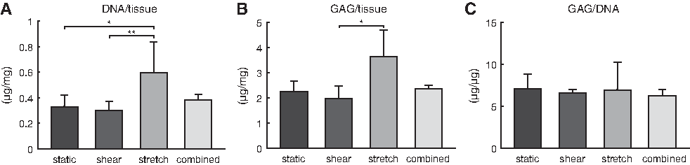
Result of the biochemical assays.
Mechanical properties
Mechanical properties are an important measure of the functional performance of load-bearing, cardiovascular tissues. Therefore, the sample's circumferential and axial moduli were quantified in a biaxial tensile testing setup (Fig. 8A). From the resulting stress–strain curves (Fig. 8B), the slopes at 5% and 10% strain were quantified. Since native tissues exhibit a typically nonlinear stress–strain response, the ratio between the slopes was computed as a measure of nonlinearity.
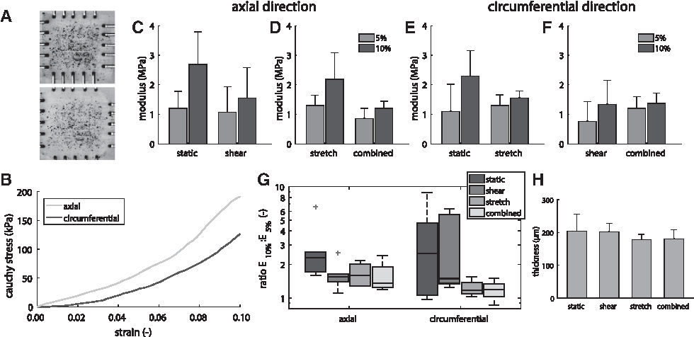
In the axial direction (i.e., the shear direction), the application of shear stress slightly decreases the slope at 10% strain, but not at 5% (Fig. 8C), whereas the application of shear stress in addition to strain decreases the slope both at 5% and 10% strain (Fig. 8D). Pairwise comparisons between E10% (slope at 10% strain) and E5% (slope at 5% strain) reflect this behavior, where static conditions result in the most nonlinear stress–strain response, as E10%/E5% ∼2.5 (Fig. 8G, axial direction).
In the circumferential direction (i.e., the cyclic stretch direction), the application of stretch (either with or without shear stress) resulted in a more linear stress–strain response, as the ratio between E10% and E5% approaches unity (Fig. 8G, circumferential direction). This can be attributed to the increased stiffness at 5% strain (Fig. 8E, F) and an additional decreased stiffness at 10% strain compared to no loading (Fig. 8E).
It is worth nothing that, in addition to the more linear stress–strain response, the application of cyclic stretch during culture also resulted in a decreased sample thickness, which might indicate a slight elongation or compression of the constructs (Fig. 8H). However, this could not be quantitatively confirmed in this study.
Discussion
In this study, we present the design and validation of a new bioreactor to culture vascular tissues. The bioreactor is developed to allow for the systematic investigation of the contributions of controlled levels of hemodynamic loads, that is, shear stress and cyclic stretch, on cell-induced matrix growth and remodeling in 3D TEVGs. Our experimental validation demonstrates the sustainability of long-term loading of cell-seeded scaffolds using the platform.
The unique feature of the bioreactor system is its independent control over shear stress and cyclic stretch, which are inherently coupled to each other in conventional setups. The decoupling of these stimuli is currently mostly limited to 2D cultures in microfluidic devices.21–23 For example, the lung-on-a-chip developed by Huh et al. generates uniaxial stretch across the microfluidic channel by applying vacuum in two side chambers that are separated from the microchannel by a thin flexible wall. 21 However, such 2D approaches do not take into account the cell's 3D microenvironment, which plays an important role not only in transmitting macroscopic stresses to the cell but also in determining cellular behavior itself. 24 Furthermore, a 2D approach is not suitable to study long-term growth and remodeling of developing tissues. Mesofluidics-based approaches offer alternative solutions to systematically investigate different levels of stretch and shear stress in 3D tissue-engineered constructs, by combining the ease of applying mechanical cues in microfluidic devices with the 3D environment of scaffolds. The first steps toward such bioreactors have been made to study the mechanobiology of engineered heart valve tissues,25,26 but bioreactors to culture blood vessels, where the mode of mechanical stimulation fundamentally differs from that in heart valves, are lacking.
In the blood vessel bioreactor presented in this study, the stimuli are decoupled through the use of two independent pumps to perfuse medium and to distend the scaffold-wrapped silicone tube in a computationally optimized culture chamber. This allows us to systematically study the contribution of various levels of hemodynamic loading on ECM properties. The effect of combined multiaxial mechanical stimulation on cell behavior, such as alignment and migration, 27 has already been shown not to be the equivalent to the superposition of the effects from the individual stimuli.28,29 Our preliminary data further suggest that both types of hemodynamic loads contribute to cell alignment, but that the contribution of shear stress overrules stretch-induced cell proliferation and collagen production (Figs. 6 and 7). Similar effects of stretch on vascular-derived cell organization and proliferation have been previously observed in cyclically stretched and constrained tissues,30,31 which are thought to be mediated by Rho signaling. 32 On the other hand, as opposed to stretch, laminar WSS has been found to reduce cell proliferation27,33 and induce perpendicular cell alignment in smooth muscle cells.27,34 Interestingly, the (myo)-fibroblasts in this study show the opposite response: they aligned in the direction of shear. This discrepancy may be due to differences in cell source, scaffold geometry, or axial constraints. The data from this study further indicate that stretch seems to strengthen the tissue at the applied stretch level of ∼1.05, but weakens the tissue at higher stretch levels of ∼1.10, leading to a more linear stress–strain response (Fig. 8). This response may be a result of elongation or compression of the cyclically stretched tissues. To confirm this relationship, the thickness and length of tissue-engineered constructs must be monitored during dynamic cultures, for example using a bioreactor that allows mechanical stimulation and testing during tissue culture. 35
Taken together, these results intriguingly suggest that cells in the scaffold tune the production and organization of the ECM in response to hemodynamic loading. These adjustments result in reduction in the nonlinearity of the construct mechanical properties. In the context of in situ TE, these insights can guide scaffold design, such as geometry, fiber anisotropy, and fiber size.
It is important to note that the experimental tests performed in this study involved a 10-day culture period during which the HVSC-seeded scaffolds were exposed to mechanical conditioning. Although this protocol is useful to test the robustness of our bioreactor and already provides interesting data on the different hemodynamic loadings, the 10-day period was not long enough to identify the effects of these mechanical stimuli in the tissue-engineered matrix and organization. Indeed, multiple weeks of culture are usually required for an engineered tissue to develop (e.g., Huang et al. 31 ). Future experiments with the bioreactor are aimed to lengthen the culture periods to at least 3 weeks, to detect all matrix components under different types of loading. Furthermore, the outside of the graft can be seeded with endothelial cells, forming the barrier between the medium and the rest of the graft.
One of the limitations of this setup is that, although the application of mechanical loading to the scaffolds is fully automated, no feedback is incorporated yet to maintain shear stresses and stretches at a constant level under changing external factors. To illustrate, cyclic stretch needs to be manually tuned by adjusting actuator displacement into a fully closed, air-tight, hydraulic reservoir to which the flow chambers are attached. As long as the hydraulic reservoir is completely leak free, the resulting stretch on the samples can be maintained over long periods of time. However, a slight leakage of air into this reservoir will result in a drop in the applied stretch. In our experiments, air bubbles tended to develop in the reservoir, requiring degassing on a daily basis to ensure constant stretch conditions during the entire culture period. At present, we are working on resolving these practical issues, for instance by using pressure-controlled rather than displacement-controlled actuators.
Conclusions and Outlook
To summarize, we have developed a novel bioreactor to quantify the individual and coupled effects of shear stress and cyclic stretch on tissue growth and remodeling. The bioreactor can successfully culture up to eight vascular constructs under various loading conditions, and our experimental validation revealed the relevance of decoupling the effects of shear stress and cyclic stretch on ECM formation. Due to its design, the bioreactor is particularly suited to investigate the interplay between hemodynamics and in situ TE processes, such as wound healing and tissue regeneration.
Footnotes
Acknowledgments
We thank Dr. Ir. M. van Turnhout for his contribution to the code for the analysis of actin fiber distributions. We thank Prof. Dr. Ir. F. Baaijens for the fruitful discussions about the concept of the bioreactor. This study (436001003) is financially supported by ZonMw and the Dutch Kidney Foundation.
Author Contributions
E.E.v.H., T.B.W., A.I.P.M.S., C.V.C.B., and N.A.K. conceptualized the idea behind the bioreactor. E.E.v.H., T.B.W., M.C.M.R., and J.A.B. were involved in the concept, design, and production of the bioreactor. E.E.v.H., M.A.J.v.K., and K.G. developed the software for the numerical simulations and the bioreactor. E.E.v.H. and T.B.W. conducted the experiments and analyzed the data. E.E.v.H. wrote the article. All authors were involved in the review and editing of the article. A.I.P.M.S., C.V.C.B., and N.A.K. supervised the project. C.V.C.B. managed the research and acquired funding to execute the project.
Disclosure Statement
No competing financial interests exist.
References
Supplementary Material
Please find the following supplemental material available below.
For Open Access articles published under a Creative Commons License, all supplemental material carries the same license as the article it is associated with.
For non-Open Access articles published, all supplemental material carries a non-exclusive license, and permission requests for re-use of supplemental material or any part of supplemental material shall be sent directly to the copyright owner as specified in the copyright notice associated with the article.