
Abstract
Peri-implant endosseous wound healing involves cascades of cellular and molecular events that lead to the integration of the implant to the recipient bone. Currently, tools are lacking to track peri-implant healing events at high spatiotemporal resolution in vivo. A cranial window chamber model (cranial implant window chamber [CIWC]), which is compatible with confocal and multiphoton intravital microscopic imaging systems, has been developed for spatiotemporal tracking of angiogenesis, and cellular dynamics in the peri-implant wound site. In this study, we describe a step-by-step procedure for implantation of the CIWC in the calvaria of fluorescent reporter mice with endogenously labeled mesenchymal progenitor cells. The specific application of this model to track angiogenesis and cell recruitment around calvarial implants is demonstrated by in vivo images. Moreover, we developed a software platform for image processing and analysis using a MATLAB graphical user interface (GUI) and have used the created GUI for image processing and quantitative analysis of changes in vascular and cellular organization.
Impact Statement
These new experimental methods allow us to image, and quantify, angiogenesis and perivascular cell dynamics in the endosseous healing compartment. As such, the method is capable of providing a new perspective on, and unique information regarding, healing that occurs around orthopedic and dental implants.
Introduction
M
Angiogenesis is considered an essential prerequisite to osteogenesis. 1 Capillaries carry oxygen and nutrients to the wound site and serve as a route for inflammatory and stromal progenitor cells to the site of injury. 2 Immunohistochemistry3–5 or ex vivo vessel perfusion 6 are the techniques used to assess peri-implant angiogenesis; however, they fail to provide spatiotemporal information regarding either the vascular or perivascular peri-implant compartments.
Intravital microscopy (IVM), defined as imaging of live animals at microscopic resolutions, 7 is a powerful tool for longitudinal biological imaging. IVM is often combined with an optically transparent window chamber to make the organ of interest accessible for long-term imaging. These tools reduce the need for repeated surgeries and, therefore, the number of animals used. Thus far, several imaging windows have been developed for deep-tissue optical imaging in mice.8,9 Cranial and femoral window chamber models have been commonly used to uncover mechanisms of bone healing.10–12 However, the information obtained from bone defect healing models is not generalizable to peri-implant healing due to the inherent variations in signaling molecules and microenvironment conditions.
Therefore, we developed a novel cranial implant window chamber (CIWC) to longitudinally track postsurgical tissue regeneration in the peri-implant wound site using IVM. This model integrates a custom-designed murine cranial titanium implant with an optically transparent window chamber compatible with both confocal and multiphoton microscopic imaging systems. The CIWC enables assessment of microvascularization rate and morphology in 3D over time, as we have recently shown. 13 However, we also show in this study that, when combined with various in vivo cell-labeling strategies,14–16 we can directly assess the migration, function, and interaction of vascular, stromal, and immune cells within the peri-implant wound site.
To quantify changes in confocal and two-photon images over time, we developed a platform for image processing and analysis using a MATLAB graphical user interface (GUI). This GUI measures the rate of angiogenesis, assesses the temporal morphometric network changes, and identifies and counts the number of fluorescently labeled cells in 3D stacks.
In this study, we explain the step-by-step surgical procedure for implantation of the CIWC in the calvaria of transgenic mice with endogenously labeled mesenchymal progenitor cells (MPCs). The CIWC functionality has been shown through imaging of FITC-dextran-labeled blood vessels and tdTomato progenitor cells in the peri-implant wound compartment. Representative images have been analyzed using the custom-coded GUI.
Materials Required
Custom-designed titanium implants (ZimmerBiomet Dental) (Fig. 1a).
Rodent anesthesia equipment
A delivery system for 70:30 O2/N2O carrier gas (Cat. No. 373; Dre Veterinary).
Isoflurane.
Ketamine (Narketan, DIN 02374994, dose: 80 mg/kg)/xylazine (Rompun, DIN 02169606, dose 13 mg/kg) mixture
Animal model
Transgenic and nontransgenic mice can be selected according to the research topic. In this study, we used a transgenic mouse line having perivascular mesenchymal cells labeled with tdTomato (kindly provided by Dr. Underhill, University of British Columbia, BC, Canada).
Reagents and surgical/imaging materials
Mouse razor (Cat. No. SKU 08685; Wahl).
10% PVP-I (betadine) solution (Cat. No. 109-08; Loris).
Isopropyl alcohol 70% (Commercial Alcohols).
Sterile gown, mask, and hair net (Kimberly-Clark Professional).
Sterile surgical gloves (Cat. No. 57850021; Ansell).
Sterile towels and drapes (Cat. No. DYNJP2405; Medline).
Tweezers (Cat. No. 12-000-132; Fisher Scientific).
Dissecting scissors (Cat. No. 08-935; Fisher Scientific).
Periosteal elevator (Cat. No. 97-0530; Sklar Corporation).
Forceps (Cat. No. S17323; Fisher Scientific).
Plastic forceps (Cat. No. 22-261-826; Fisher Scientific).
Custom-made trephine (ZimmerBiomet Dental) (Fig. 1b).
Low-speed dental handpiece (ZimmerBiomet Dental)
Standard IV soft flexible catheter (Cat. No. NPMCI2225Z; Nipro Medical).
Heating pad (Sunbeam Health).
Heat lamp (Cat. No. HL0100; Morganville Scientific).
Cotton gauze (Cat. No. PRM25444; Medline).
Cotton swabs (Cat. No. MDS202050; Medline).
Round glass coverslip. Eight millimeter in diameter, #1 thickness (Cat. No. GG-8; neuVitro).
3M™ ESPE™ Scotchbond™ Universal Adhesive Intro Kit (Cat. No. 41254; 3M™).
3M™ ESPE™ Filtek™ Supreme Ultra Flowable Restorative (Cat. No. 6032A1; 3M).
DeepCure-S LED Curing Light Machine (Cat. No. 76976; 3M).
Tear-gel eye lubricant (Cat. No. L2412369; Bausch & Lomb).
Analgesic: buprenorphine (Vetergesic, DIN 02342510); dose: 0.05 mg/kg.
Fluorescein isothiocyanate (FITC)-dextran 2 MDa (Cat. No. FD2000S; Sigma-Aldrich); dose: 0.1 mg/mouse; 100 μL injected/mouse.
Ultrafine 6 mm insulin syringe (Cat. No. 324703; BD).
Sterile saline (Cat. No. JB1323; Baxter).
Modeling clay.
Heated microscope stage.
Custom-made metallic restrainer.
Confocal/two-photon fluorescence imaging microscope (LSM 710; Carl Zeiss, Germany).
Choice of objectives:
FLURA 5 × /0.25 Plan-Apochromat 10 × /0.45 Plan-Apochromat 20 × /1.0 DIC, water immersion lens

Technical drawing of the custom-designed titanium cross implant and the dental trephine.
Image processing and analysis
Image processing software.
Zen lite (Zeiss, Jena, Germany).
MATLAB (MathWorks, R2016a).
Euthanasia and sample harvesting
CO2 euthanasia chamber.
Prefill formalin containers (Cat. No. 1202J57; Thomas Scientific).
Methodology
Implant design and fabrication
Manufacture the cruciate-shaped implants (4 mm in diameter and 500 μm thick) from grade IV commercially pure titanium. First drill a central 2 mm hole along the axis of the titanium rod stock. Machine the cutouts to create a cruciate cross section and then slice the rod to obtain individual implants. The central hole can be used to bolt together a stack of implants to facilitate surface treatment (Fig. 1a).
Note: The surface of the implant can be subjected to various modification procedures depending upon the nature of the experimental question to be addressed.
Pack the implant individually. Sterilize by gamma-irradiation (25 kGy).
Surgical procedure
Sterilization and instrumentation setup
Autoclave surgical instrumentation 24 h before commencing surgery.
Disinfect surgical table using 70% isopropyl alcohol. Furthermore, arrange the surgical stage to ensure a heating pad will keep the animal warm.
Prepare the analgesia by first weighing and marking the animal. Based on animal weight, prepare the buprenorphine 0.1 mg/kg and inject using an insulin syringe.
Anesthesia
Turn on the rodent anesthesia delivery system. Ensure that there are adequate levels of carrier gas (O2/NO2 mixture) and isoflurane available before beginning the procedure. Adjust the oxygen flowmeter to 0.5 L/min and the isoflurane vaporizer to 5%.
Place the animal in the induction chamber and start sedation. The animal should stop moving after the first couple of minutes of exposure to 5% isoflurane.
Upon loss of consciousness, gently remove the animal from the induction chamber and transfer it to the surgical stage connected to a Bain circuit carrying 2–3% isoflurane. Ensure the animal is securely fastened to the nose cone for maintenance of anesthesia.
Preoperative procedures
To administer the analgesic, carefully restrain the animal and use the insulin syringe to inject the buprenorphine subcutaneously. This should provide the animal with pain relief before, during, and after surgery. Furthermore, apply tear gel as necessary throughout the procedure to mitigate eye dryness.
Be sure to determine adequate depth of anesthesia by monitoring pedal withdrawal and palpebral reflexes before proceeding. As well, take care to consistently monitor the respiration and skin/mucous membrane color of the animal throughout the entire length of the procedure.
Once the animal is sufficiently anesthetized, shave the animal's head, specifically the area between the ears.
Disinfect the surgical site by gently cleaning the area with cotton gauze soaked in 7.5% betadine, followed by more gauze dipped in 10% betadine, and 70% isopropyl alcohol.
Operative procedures
As shown in Fig. 2a–k:
Carefully lift the skin at the midpoint between the ears using tweezers. Using sharp curved scissors cut a hole in the skin ∼8 mm in diameter and expose the periosteum.
Elevate the periosteum using jewelers forceps, cut with scissors, and reflect with a periosteal elevator to expose the calvaria. Gently scrape the surface of the calvaria to remove the remaining periosteum.
Carefully use a custom-made dental trephine connected to a low-speed dental drill to create a midline 4 mm diameter osteotomy in the skull. Take care to continuously irrigate the surgical area with sterile saline during this step of the procedure. Note: A laser-marked stop line (200 μm from the tip of the trephine) indicates maximum penetration depth.
Elevate and remove the circular bone created within the osteotomy using the periosteal elevator and ensure that the dura matter remains intact. To mitigate bleeding in injured areas, continuously drop phosphate-buffered saline in lesions and apply mild pressure to the defect with cotton swab until bleeding arrests.
Lift the implant by the central hole using tweezers and carefully place it in the circular osseous defect.
Cover the area of exposed skull around the osseous defect with Scotchbond™ dual-cure adhesive dental resin.
Once the resin is adhered, layer a ring of dental restorative material directly on top of the Scotchbond while maintaining a 1.5 mm distance from the edge of the osteotomy.
Secure the implant by positioning a small 8 mm diameter sterile glass coverslip on top of the restorative ring encasing the implant. Note: Use plastic forceps to handle the coverslip to avoid scratching the glass.
Securely fasten the glass to the implantation site by gently pressing down on the coverslip with plastic forceps.
Light cure the restorative material to the glass coverslip using a light curing machine (10 s) to create an airtight seal that prevents infection.
Next, apply another ring of restorative material in the 1.5 mm gap between the skin and Scotchbond, while manipulating the animal's skin to ensure it is adhered to the material.
Upon correct positioning, further secure the window by light curing it a second time (20 s) to ensure the implantation is properly sealed.
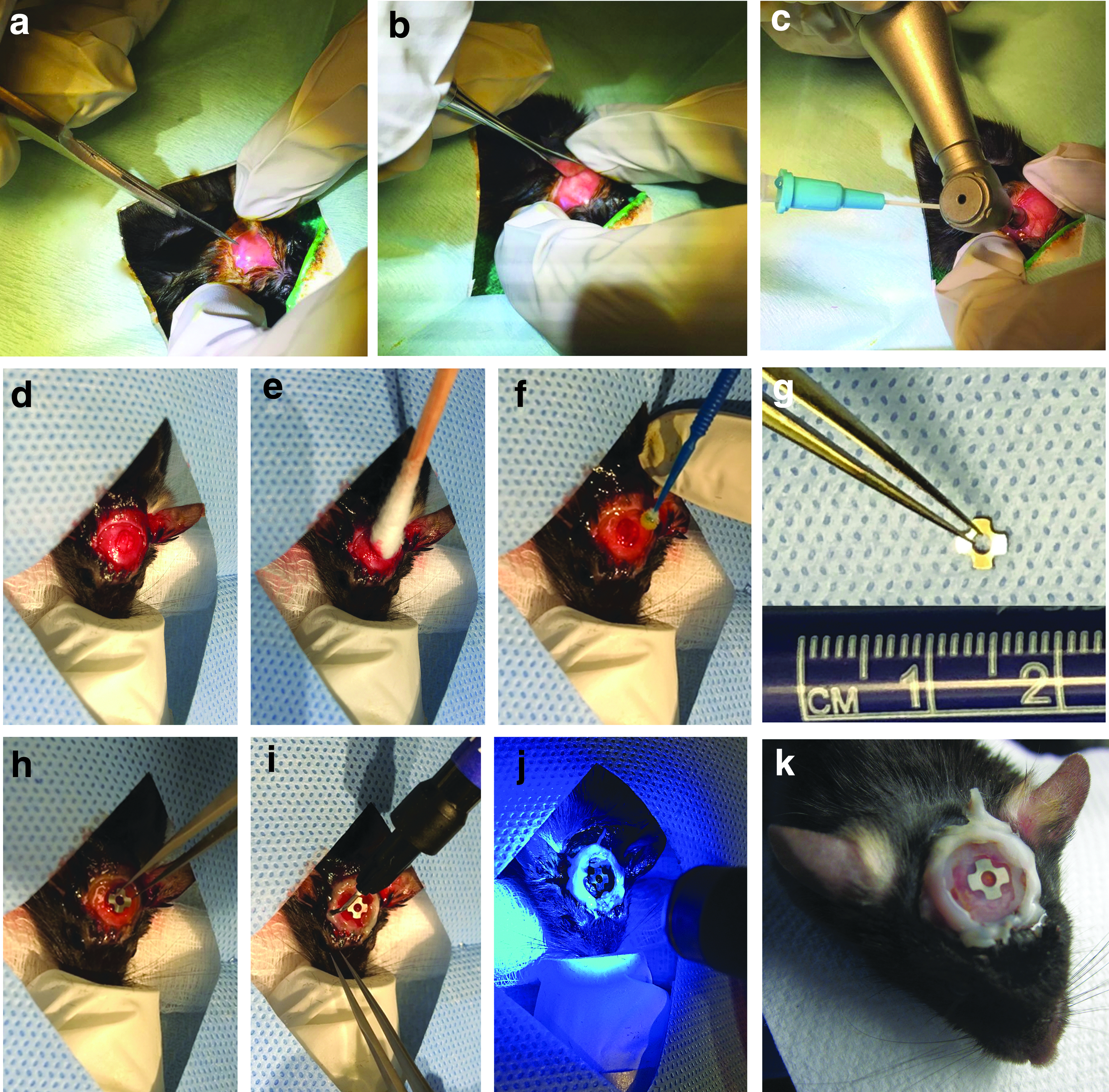
Step-by-step surgical procedure for placement of the implant and the window chamber in the calvaria of a mouse.
Postoperative procedures
After surgery, carefully remove the animal from the rodent anesthesia machine and transfer it to a heating pad overlaid with a surgical pad to maintain physiological body temperature. For extra precaution, use a heat lamp to ensure the animal is sufficiently warm.
Carefully administer analgesia (buprenorphine) to the animal by subcutaneous injection.
Monitor the animal's muscle tone and breathing and return it to the cage once it has become ambulatory.
Continue administration of buprenorphine twice a day for 3 days after surgery and monitor the animals closely to ensure they resume normal activity.
Intravital microscopy
Preimaging procedures, sterilization, and instrumentation setup
Switch on the microscopy apparatus (Fig. 3a) and allow for adequate instrument warm-up.
Make sure to disinfect any areas of the apparatus that the animal may come into contact with by wiping down the area with 70% isopropyl alcohol.
Carefully remove the animal from its cage. Gently restrain the animal and anesthetize it by injecting 350–400 μL ketamine/xylazine mixture at 80:13 mg/kg intraperitoneally (Note: This was approved by the Institutional Animal Care Committee, and we have not had any experience with adverse effects). Return the animal to its cage and monitor its behavior until the animal loses consciousness. Confirm proper anesthesia by testing for pedal reflex.
Upon loss of consciousness, remove the animal from its cage and transfer it to a sterile surgical pad overlying a heating pad to maintain its physiological body temperature. To avoid dryness of the eyes, apply tear gel as needed.
Administer FITC-dextran to the animal through tail vein injection using an ultrafine insulin syringe. To better visualize the tail vein, warm up the animal under the heat lamp 10 min before injection.
Once the agent has been administered, transfer the animal to the imaging heated stage.

Confocal microscopy setup.
Image acquisition using combined two-photon and confocal laser scanning microscopy
Stabilize the head of the animal on the stage by manipulating its position using modeling clay. Allow the rest of the body to relax idly on the stage.
To further minimize artifacts caused by respiration, fix the window chamber into place by carefully mounting a metallic restrainer above the animal's head as demonstrated in Figure 3b. Manipulate the modeling clay to further secure the restrainer.
Once the window chamber is in place and aligned with the microscope objective lense, use a cotton swab soaked in 70% isopropyl alcohol to clean the glass coverslip on the window.
To image the vasculature, adjust the light source excitation and emission wavelength settings to 488 and 500–550 nm, respectively. Ensure the image size is at least (1024 × 1024 pixels). Adjust the pixel dwell to 0.8 μs.
A second channel can be created to illuminate tdTomato progenitor cells by adjusting the excitation and emission settings to 562 and 573–615 nm, respectively.
For visualization of the implant surface, create a third channel with excitation and emission wavelength settings of 633 and 622–666 nm, respectively.
In addition to fluorescence channels, bone matrix can be imaged by two-photon microscopy through second harmonic generation (SHG). Note: All excitation and emission wavelengths are summarized in Table 1.
Use the XYZ-axis controller for spatial orientation of the implant area and to identify critical landmark locations, including the bone-implant interface.
Adjust the acquisition parameters: 2–5% laser power, pinhole: 1–2 Airy unit, and keep the gain <700.
Acquire images using 5 × , 10 × , 20 × , and 40 × water/oil immersion objectives.
For 3D imaging of the window chamber, use the XYZ-axis controller to determine the XYZ boundaries of the wound site. Record the images as a series of TIFF files with dimensions of 1024 × 1024 pixels with image Z-stack sizes of 500 μm through the tissue thickness.
Guides for setting up the excitation and emission spectra for each of the channels used in this model.
SHG, second harmonic generation.
Postimaging procedures
Once imaging is complete, remove the animal from the microscope stage and transfer it to a heating pad overlaid with a surgical pad in the recovery station to maintain physiological body temperature.
Monitor the animal's respiration and muscle tone during recovery and return it to the cage once ambulatory.
Repeat these procedures longitudinally to address the objectives of the research. Ensure that image acquisition settings are maintained consistently throughout groups and imaging intervals.
Euthanasia
Place the animal in the CO2 gas inhalation chamber. Turn on the CO2 gas release adjacent to the chamber and set the flow rate to 3.0 L/min.
Remove the animal from the chamber as soon as its breathing ceases.
Perform a secondary euthanasia by cervical dislocation to ensure the animal has been sacrificed appropriately.
Sample harvesting
Remove the head of the animal from the carcass using dissecting scissors.
Fix the specimen in 10% formalin for 24–48 h.
Remove the skin surrounding the skull using dissecting scissors
Separate the mandible from the maxilla. Cut the cranial bone, including the implant window chamber, then turn the specimen upside down and use periosteal elevators to remove the brain.
The specimen is now ready for microcomputed tomography (μCT) scanning or resin embedding for histological analysis.
Image Processing and Analysis Using a Custom-Coded MATLAB-Based GUI
A custom GUI has been specifically developed for processing and analysis of the images acquired by confocal and multiphoton microscopy using the CIWC. This analysis platform uses DIPimage toolbox 17 in MATLAB as it is a powerful tool for image segmentation and quantification. The major function of this GUI is to quantify the vascular morphometric parameters and the number of the fluorescently labeled cells in the images acquired by IVM.
Download and extract the folder “GUI.” This folder contains five files:
dipstart.m Vasculature_CellCountingv3.m Vasculature_CellCountingv3.fig Vessel_Analysis.m Cell_Count.m
Download and install DIPimage (
Start and run DIPimage toolbox in MATLAB following the instructions on DIPImage User Manual. 18
For vascular processing and measuring:
Click on “Browse image” and select the maximum projection image to be processed and analyzed.
Click on “Analyze vasculature.”
For cellular processing and measuring:
Click on “Browse 3D stack.”
The 3D stack should be provided to the GUI as separate images. Select every image in the stack individually (shift+select).
Click on “Count cells.”
Representative Results
Animals showed no signs of pain or distress after surgery. The CIWC remained optically clear for IVM up to 6 weeks and was well tolerated beyond that (8 weeks was the last timepoint), which makes it suitable for long-term tissue regeneration assessments. The CIWC stabilized the implant within the cranial defect and enabled visualization of both vascular network and progenitor cells in the peri-implant wound microenvironment.
A step-by-step procedure of the CIWC placement is shown in Figure 2. The angiogenic vascular formation around the titanium implant can be visualized by intravenous injection of fluorescent dyes such as dextran-based fluorescent probes. Since visualization of blood vessels is contingent upon sufficient blood flow in vessels, this method is a fluorescent-based assessment of vascular functionality. In addition to vasculature, progenitor cells can be visualized in endogenously labeled animals or antibody labeled nontransgenic lines.
Figure 4a represents an image acquired from one healing volume (HV) around the implant at day 11 postsurgery. The vascular network is visualized by FITC-dextran and the MPCs are labeled with tdTomato. In addition to red and green channels, the organic bone matrix, which is predominantly composed of collagen fibers, can be seen in the SHG channel. Figure 4b shows SHG+ (white) bone matrix in the same HV at two different timepoints (day 28 and 43). The surface of the titanium implant can be visualized by the collection of reflected light in any fluorescence channel (here shown in blue). The woven structure of collagen fibers is visible at day 28 postsurgery; however, this structure appears to change to a less woven denser network by day 43.
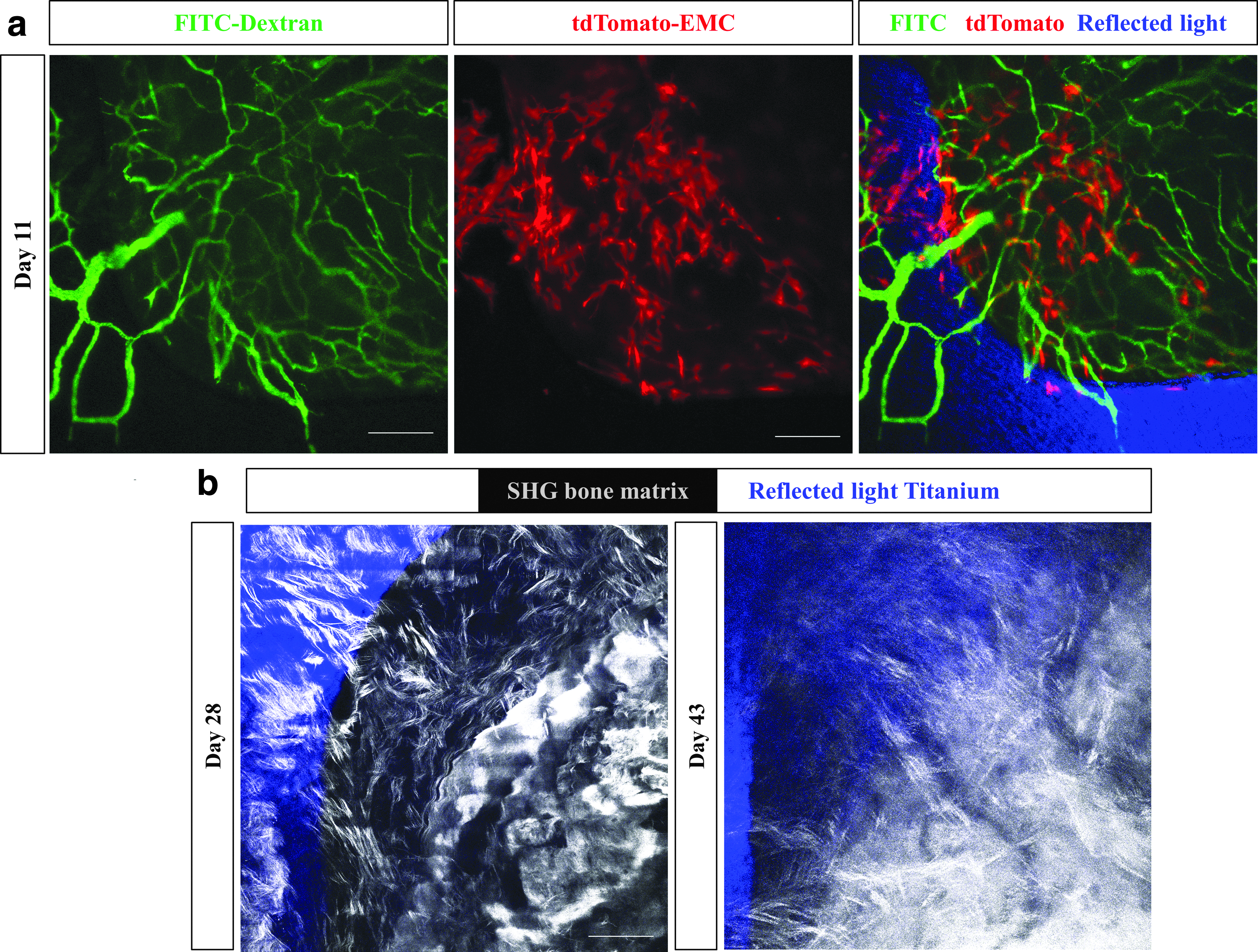
Imaging of the vascular network, mesenchymal cells, titanium implant, and bone matrix in vivo. Representative images of one healing volume 11 days postsurgery.
The GUI developed for image processing and analysis is shown in Figure 5. First, the image processing algorithm transforms RGB images into gray scale. Note: For vessel analysis, it is important to obtain a skeleton image that accurately represents the original image. To avoid excessive branching due to false segmentation of rough vessel edges, a Gaussian filter was applied to smoothen the image. The filtered image was segmented by global thresholding and a binary skeleton was obtained from the segmented image. The color mapping feature helps label detected blood vessels. The original image, the color mapped image, and the binary skeleton are shown in the GUI (Fig. 5a–c) in addition to the measured vascular morphometric parameters (Fig. 5d).
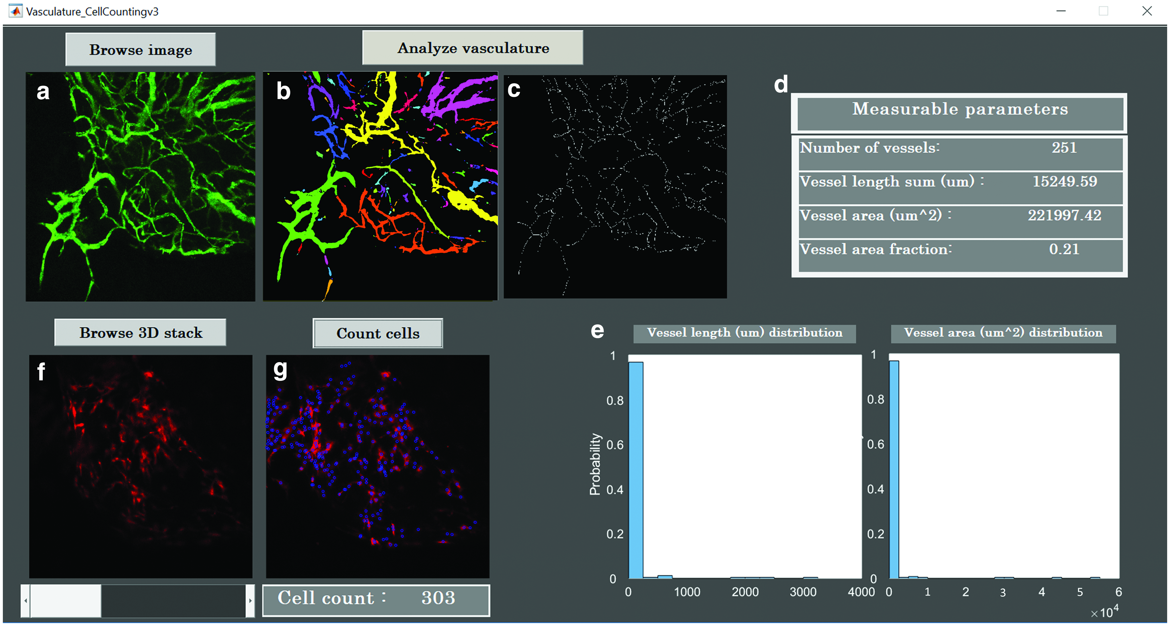
GUI for image processing and analysis. A custom-coded GUI is constructed to process and analyze confocal multichannel images.
The vessel area is the sum of the positive pixels, and the vascular area fraction is the percentage of the vascular area over the total number of the pixels in the image. Total vessel length was measured using the binarized skeleton and a vessel length histogram was obtained. The histograms of vessel length and area are both shown on the GUI (Fig. 5e).
The GUI also incorporates a feature to quantify the number of tdTomato cells, in each HV around the implant (Fig. 5f, g). This quantification was accomplished using a marker-controlled watershed segmentation (MWS) algorithm. 19 To this end, MWS segmentation was carried out individually on each 2D image in the 3D stack. Figure 6a–f show the image processing MWS steps executed on a 2D image to count cells.

Image processing steps in the red channel before cell analysis.
First, the RGB image was read and converted into a gray scale image. Next, contrast-limited adaptive histogram equalization was applied to smoothen the distribution of the intensity histogram and enhance the contrast in the image. For adaptive noise removal, the Kuwahara filter was used to ensure retention of cellular edges. Since the cell nucleus had higher intensity compared with the cytoplasm, conventional segmentation fails to provide accurate results. It was necessary to incorporate additional steps to distinguish between foreground and background. A mask was created to selectively retain the bright nuclei. The complement of the mask and the inverse of the filtered image served as an input for MWS to count closed regions. The total number of cells in each individual 2D image was calculated based on the number of connected components above a certain size threshold. The total number of cells in the 3D stack is the sum of cell counts in each individual 2D image (Fig. 6g).
To avoid duplicate cell counts, the distance between cell centroids was measured across each image slice in the 3D stack. Duplicate cells were identified by having a distance smaller than the average cell radius. The total cell count of 303 excludes duplicates. To determine the accuracy of the cell count using our platform, our results were compared with those obtained by manual counting and using Imaris 3D cell analysis. For the image shown in Figure 6 the cell counts were 303 for GUI, 306 for Imaris, and 308 for manual count. The counts were repeated with three other images at random timepoints and the maximum difference between counts in GUI and Imaris was 1.65%.
Discussion
A limited understanding of the underlying biological mechanisms and time course of peri-implant healing has impeded the development of better therapeutic strategies to control the rate and extent of healing. Although intravital imaging of bone vascularization and cellular dynamics has been previously performed during defect repair,10,20,21 until recently, 13 no high-resolution in vivo longitudinal study has been reported for peri-implant wound vascularization. In this study, we have described the cranial implant design, the detailed surgical procedure for placement of the CIWC, and provided a platform for processing and analysis of the images acquired intravitally using confocal microscopy.
There are critical steps that determine the durability, quality, and consistency of the CIWC across all samples. A fundamental step involves taking extra care not to rip or puncture the dura mater and the superior sagittal sinus while creating the midline craniotomy in the skull using a trephine. Damaging the sinus results in excessive bleeding and stimulation of an inflammatory response that affects the healing process. To preserve optical clearance for long-term imaging, superimposition of a cover glass on top of the cranial implant prevents fibrous tissue growth into the surgically exposed area.
To stabilize the window chamber and the implant, application of dental adhesive restorative material underneath and around the cover glass is crucial. Furthermore, the tight sealing of exposed bone and skin around the window chamber reduces the risk of infection. The window chamber is watertight and suitable for microscopy with water/oil immersion objectives. However, one limitation associated with this model is that the window chamber is not removable, so in case of cover glass breakage, the animal needs to be excluded from the study cohort. It is worth mentioning that we know of no reports of dental adhesive materials release leaching components that cause adverse biologic effects. However, having a control group in comparative studies, as we have previously reported, 13 will validate that the reported differences are not due to individual components of the window chamber.
Extracting numerical information requires reproducible high-quality images and tools for image segmentation and analysis. To acquire images free of motion artifacts caused by respiration and the intracranial pulse, it is important to properly immobilize the animal's head under the microscope. We used a metallic restrainer to provide a stable long-term platform on modeling clay to dampen movement. These high-quality longitudinal images were subjected to processing and analysis using the costume-coded GUI, which allows the rate of vascularization and vessel morphology to be assessed by measuring the vascular area fraction and the vessel length. The MWS algorithm quantifies the number of cells within the same region of interest across all images.
This platform is adaptable to both 2D maximum intensity projection images and 3D stacks. Our platform also provides a free open-source GUI that quantifies the number of cells in confocal and multiphoton 3D images. The 2D cell count is not as accurate as 3D count due to the undersegmentation of optical sections closer to the objective lens and oversegmentation of the sections deeper in the tissue. The accuracy of these measurements was validated by manual counting.
The CIWC provides a potential to track the migration and function of cells in the peri-implant microenvironment beyond what has been shown in this study. This intravital imaging approach can be used in various transgenic reporter mouse models, endogenously expressing fluorescent proteins to label platelets, 22 leukocytes, and endothelial cells,23,24 as examples. Alternatively, antibodies can be used for immunofluorescence labeling of the mentioned cell types.25,26 Also the surface of the implant can be modified and intravital imaging can be combined with other imaging modalities such as μCT, single-photon emission computed tomography, and micro computed tomography to study the effect of various surface modifications on the extent and rate of peri-implant wound healing. 13
The experimental protocol described in this study offers a novel approach for in vivo spatiotemporal intravital visualization of wound healing around implants in mice at cellular resolution. In addition, we have created a GUI for image processing and quantitative analysis of changes in vascular and cellular organization. Application of the CIWC in various murine strains may enable further investigation of multiple cell populations involved in the dynamic healing process around bone implants. Therefore, the described method is widely applicable to studies in the field of dental and orthopedic surgery.
Data Availability
The GUI package has been deposited in figShare with the identifier:
Footnotes
Acknowledgments
We are grateful to Zimmer-Biomet Dental, Inc. for help with the design and fabrication of the implants and the trephine. We also thank Dr. T. Michael Underhill in University of British Columbia for kindly providing the EMC-reporter mouse, the Animal Resources Center at University Health Network for veterinary assistance and postoperative care, and the Facility of Advanced Optical Microscopy (AOMF). Our special thanks to Professor Rodrigo Fernandez-Gonzalez for validating the image processing and analysis method.
Disclosure Statement
No competing financial interests exist.