
Abstract
Establishing a suitable animal model of growth plate injury is necessary to evaluate the effect of tissue engineering scaffolds on repairing the injured growth plate. However, the currently used animal models have limitations. Therefore in this study, we reported and evaluated a new modeling method termed the longitudinal disruption method, which is to make a longitudinal defect in the region of growth plate. To compare this new method with the traditional transverse disruption method, we constructed the models by both methods, respectively. To observe whether bone bridges were formed, histological sections were analyzed by hematoxylin-eosin (HE) and Masson staining at 3 weeks after modeling. The HE and Masson staining results showed the formation of bone bridges in both groups, implying that the two methods successfully injured the growth plate. However, it was unclear whether the exact injury to growth plate caused by both methods was consistent. Therefore, to evaluate the accuracy and precision of modeling method, the X-ray and micro-computed tomography (CT) were performed immediately after modeling. The percentages of accurate defect position in the longitudinal and transverse modeling groups were 88.89% and 55.56%, respectively. The micro-CT results revealed irregularly shaped defect cross sections in the transverse modeling group, whereas the defects in the longitudinal modeling group had regular shapes. The mean defect areas were 10.06 ± 0.86 and 12.30 ± 2.13 mm2 in the longitudinal and transverse modeling groups, respectively, while the difference between the actual area and the expected area were −1.94 ± 0.86 and −7.70 ± 2.13 mm2, respectively, showing the high precision of this new method. Altogether, we successfully demonstrated a new method for establishing a rabbit model of growth plate injury, which provides a simple and rapid modeling process, good modeling effect, high modeling accuracy, and convenient scaffold implantation. The new method provides an effective animal model for tissue engineering research on the repair and regeneration of injured growth plate.
Impact Statement
In recent years, an increasing number of studies have used tissue engineering scaffolds in the repair and regeneration of growth plate. However, the currently used animal models have certain limitations in the study of tissue engineering scaffold for growth plate. In this study, a new method is presented to establish a rabbit model of growth plate injury. This method is characterized by simple and rapid modeling process, good modeling effect, high modeling accuracy, and convenient scaffold implantation, which is suitable for the study of the repair effects of tissue engineering scaffolds. Altogether, this method provides an effective animal model for tissue engineering research on growth plate and facilitates the development of tissue engineering research on the repair and regeneration of injured growth plate.
Introduction
The growth plate, which is a unique type of cartilage located between the epiphysis and metaphysis at both ends of immature lone bones, controls longitudinal skeletal growth in children. The growth plate is vulnerable to injuries caused by infections, fractures, and tumors.1,2 Epidemiological data suggest that growth plate injuries account for 15–30% of all pediatric skeletal injuries.3,4 The self-repair capacity of the growth plate is inherently limited due to the lack of vasculature and nerves. As a result, injured growth plate cartilage tends to be replaced by bone tissue, which leads to the formation of a bone bridge and the loss of biological function. This process contributes to clinical manifestations such as leg length discrepancy and angular deformity of the limb.2,5
At present, the clinical treatment for the above issue involves traditional bony bridge resection followed by filling the defect with fat, muscle, and/or bone cement; limb correction or lengthening surgery can also be performed,6–8 although the surgical outcomes are not satisfactory, and the procedure may lead to secondary damage to the growth plate.1,9 Therefore, effective methods for promoting the repair of injured growth plate and improving therapeutic outcomes are urgently needed. Recently, great progress has been made in tissue engineering for the repair and regeneration of injured growth plate.1,10 In this approach, a scaffold is used as a carrier of stem cells and related growth factors. The stem cells directionally differentiate into chondrocytes, which promote cartilage regeneration to repair the injured growth plate.11–13
Several recent studies have applied tissue engineering techniques for the repair of injured growth plate.1,2,10 However, to confirm the in vivo repair ability of these tissue engineering techniques, it is necessary to construct a suitable and effective animal model of growth plate injury. At present, the commonly used animal models of growth plate injury include the mouse and rat proximal tibial central drill disruption models and the rabbit proximal tibial peripheral transverse disruption model.2,10,14 The central drill disruption model is the most widely used. Since the diameter of defect in this model is generally only 2–3 mm, this model is mainly used for pathological studies of injured growth plate or studies on the repair effects of injectable materials; it is difficult to implant tissue engineering scaffolds with high biomechanical strength in this model for repair research.
For the rabbit peripheral transverse disruption model, the growth plate cartilage of the proximal tibia is damaged parallel to the growth plate.15–17 However, the structure of the growth plate is not completely horizontal (it is actually wave shaped 10 and angled 14 ), and individual variability exists among rabbits. Although this model allows scaffold implantation, the size of the growth plate defect is difficult to control precisely and shows poor repeatability in the experiments, making it difficult to obtain stable study results. Taken together, the currently used animal models have certain limitations in the study of tissue engineering scaffold. Thus, in this study, we reported the development and evaluation of a new method for modeling growth plate injury, termed the longitudinal disruption method.
Materials and Methods
All procedures were in accordance with the “Guide for the Care and Use of Laboratory Animals” and approved by the Ethics Committee of Nanjing Children's Hospital. We purchased 26 six-week-old New Zealand white rabbits from Nanjing Medical University. The 26 rabbits were randomly divided into the longitudinal modeling group and the transverse modeling group. Rabbits in the longitudinal modeling group received a longitudinal defect (3 mm in length × 4 mm in depth × 5 mm in height; Figs. 1A–C) and the implantation of metal scaffold (Fig. 1D), while those in the transverse modeling group received a transverse defect (5 mm in length × 4 mm in depth × 3 mm in height; Fig. 1E–G) and the implantation of metal scaffold (Fig. 1H).

Schematic diagram of both modeling methods for constructing the growth plate disruption model. The growth plate longitudinal disruption model was created by longitudinal injury from the proximal part to the distal part of the growth plate
To control the individual difference of the operator, the longitudinal disruption model and transverse disruption model were established by the same operator and assistant. The time from the start of drilling to the implantation of the scaffold was recorded as the modeling time. To verify the modeling effect of both methods, four rabbits in each group 3 weeks after modeling were histologically sectioned for hematoxylin-eosin (HE) and Masson staining to observe whether bone bridges were formed. To evaluate the accuracy and precision of both methods, the other nine rabbits in each group performed X-ray and micro-computed tomography (CT) immediately after modeling, which assessed the injury of growth plate.
Experiment
Modeling procedures
The rabbits were anesthetized with 2.5% pentobarbital sodium at 1.0 mL/kg via intravenous injection at the ear margins. The surgical area from the medial malleolus to the pelvis was culled clean of fur, and the rabbit was placed supine and secured on the animal surgical table. After wiping the lower limb with alcohol cotton balls, the foot was wrapped with a sterile surgical glove. The surgical site was then sterilized with gauze soaked in povidone-iodine. Finally, the surgeon put on sterile gloves and laid a sterile surgical drape over the rabbit that allowed the lower limb to extend through the central cavity.
A longitudinal skin incision of ∼2 cm was made from the medial gap of the knee joint toward the proximal tibia, and the soft tissue was separated. The growth plate of proximal tibia was exposed, and the proximal 1 mm of growth plate served as the drilling site (Fig. 2A). The soft tissues around the drilling site (e.g., the fascia and muscle) were scraped away with a scalpel to allow for drilling. A 2-mm-wide burr was attached to the matching rotary tool, and the drilling depth was limited to 4 mm by mounting a stopper to the burr. The burr was then drilled perpendicular to the tibial shaft at 10,000 rpm at the drilling site. After the drilling depth reached 4 mm, the burr was moved along the longitudinal axis of tibial shaft across the entire layer of growth plate to the proximal tibial metaphysis. During the modeling process, the length and height of the defect were controlled to 3 and 5 mm, respectively. This method successfully established the growth plate longitudinal disruption model.
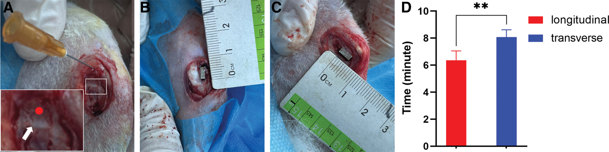
Intraoperative photographs showing model construction.
For the transverse disruption model, the transverse defect was constructed based on the modeling method of Yu et al. 10 And to have comparability between the two models, the transverse defect was set to 5 × 4 × 3 mm.
Evaluation of the modeling effect
After constructing the models, we designed and prepared metal scaffolds with dimensions of 3 × 4 × 5 mm via three-dimensional (3D) printing according to the expected defect size, which can be used to help evaluate the location of the defect and the degree of matching between the defect and scaffold. We then implanted the metal scaffolds into the defects of both models (Fig. 2B, C). The time from the start of drilling to the implantation of the scaffold was recorded as the modeling time. The scaffolds were removed from four randomly selected rabbits from each group. After washing with physiological saline and carefully suturing the periosteum, the subcutaneous tissue was continuously stitched layer by layer, and the skin was sutured. After surgery, the rabbits were kept as normal in separate cages without immobilizing the limbs.
Penicillin was intramuscularly injected daily at 20,000 units/kg for 3 day postoperatively to reduce the risk of infection. Histological sections were analyzed by HE and Masson staining at 3 weeks after surgery to determine whether bone bridges had formed in the area of the injured growth plate. The other nine rabbits in each group were assessed by X-ray immediately after surgery, and the defect locations were evaluated in the anteroposterior and lateral radiographs. The criterion for accurate defect position was as follows: in the anteroposterior and lateral radiographs, the scaffold (1) was perpendicular to the growth plate in the longitudinal modeling group or parallel to the growth plate in the transverse modeling group; and (2) affected the full-thickness growth plate. Finally, the metal scaffolds were removed, and the cross-sectional defect shape was evaluated by micro-CT. The cross-sectional area of the growth plate defect was also measured by Image J software.
Statistical methods
Quantitative data are presented as the mean ± standard deviation, and statistical differences were analyzed by analysis of variance. Qualitative data were subjected to Fisher's exact probability test to analyze statistical differences. Statistical analysis was performed using GraphPad Prism 8.0. Comparisons with *p < 0.05, **p < 0.01, and ***p < 0.001 were considered statistically significant; NS represents no significant difference.
Results
The growth plate longitudinal disruption method successfully resulted in growth plate injury followed by bone bridge formation
To compare the modeling efficiency of both methods (the new longitudinal disruption method and the traditional transverse disruption method), 26 rabbits were randomly divided into two groups and modeled using the corresponding method on the lower limb followed by scaffold implantation. During the modeling procedure, the modeling time of each group was recorded. The mean modeling time in the longitudinal modeling group was 6.35 ± 0.70 min, significantly less than that in the transverse modeling group (8.08 ± 0.54 min; p < 0.05; Fig. 2D).
To verify whether bone bridges were formed after growth plate injury in both groups, four rabbits in each group were histologically sectioned for HE and Masson staining at 3 weeks after modeling. In both groups, the medial region of the proximal tibial growth plate showed obvious bone infiltration, and the previously rounded chondrocytes disappeared and were replaced by osteocytes and osteoblasts, indicating bone bridge formation (Fig. 3A–D). In one case in the transverse modeling group, the location of injury was low, and only the lower part of the growth plate was destroyed; however, the bone bridge was still formed (Fig. 3E, F). Thus, both longitudinal disruption method and transverse disruption method could lead to the formation of bone bridge. In other words, the two methods successfully injured the growth plate cartilage followed by forming bone bridge, however, whether the exact injury to growth plate caused by both methods was consistent needed further study.

Results of hematoxylin-eosin staining and Masson staining in the longitudinal and transverse modeling groups at 3 weeks after modeling.
Compared with the transverse modeling method, the longitudinal modeling method resulted in more precise growth plate injury
The other nine rabbits in each group were used to assess the injury to growth plate by both modeling methods by taking X-ray and micro-CT immediately after modeling. The position, shape, and size of actual defect in both models were compared to evaluate the accuracy and precision of the two methods. The accurate defect position was indicated as follows: the scaffold was perpendicular or parallel to the growth plate and affected the full-thickness growth plate on the anteroposterior and lateral radiographs (Fig. 4A, B). The defect position was judged to be inaccurate when the scaffold was inclined or did not affect the full-thickness growth plate (Fig. 4C, D). The rates of accurate defect position were 88.89% (8/9) in the longitudinal modeling group and 55.56% (5/9) in the transverse modeling group. In the longitudinal modeling group, the numbers of accurate defect positions were eight and nine in the anteroposterior and lateral radiographs, respectively. In the transverse modeling group, the numbers of accurate defect positions were six and six in the anteroposterior and lateral radiographs, respectively (Table 1).

X-ray and micro-computed tomography results in the longitudinal and transverse modeling groups immediately after modeling.
Accuracy Rates of Defect Position in Both Groups
La, longitudinal modeling group; Tb, transverse modeling group.
The micro-CT results showed that the cross-sectional shapes of defects in the longitudinal modeling group were regular (Fig. 4E) and close to the expected shape (Fig. 1B) that is suitable for implanting tissue engineering scaffolds. In contrast, the cross-sectional shapes of defects in the transverse modeling group were mostly irregular (Fig. 4F).
For each rabbit, three micro-CT images of the growth plate defect were randomly chosen to measure the defect area using Image J software, and the mean value was calculated as the cross-sectional area of growth plate defect. The mean growth plate defect areas were 10.06 ± 0.86 and 12.30 ± 2.13 mm2 in the longitudinal and transverse modeling groups, respectively (p < 0.05). However, the expected area of defect were 12 and 20 mm2 in the longitudinal and transverse modeling groups, respectively. And the difference between the actual area of defect and the expected area of defect were significantly different (p < 0.05), with values of −1.94 ± 0.86 and −7.70 ± 2.13 mm2 in the longitudinal and transverse modeling groups, respectively (Fig. 4G). Thus, the area of the growth plate defect was closer to the expected defect area in the longitudinal modeling group. Above all, the evaluation results showed that the new longitudinal disruption method was more accurate and precise in injuring the growth plate than the traditional transverse disruption method.
Discussion
Tissue engineering provides a new strategy for the repair of injured growth plate cartilage. This approach involves three main components: the scaffold material, seed cells, and cell-regulated growth factors. 18 The scaffold is a critical component in cartilage tissue engineering; it acts as a carrier of seed cells and growth factors, which participate in repairing injured cartilage. 15 The scaffold should have good biocompatibility and stable physicochemical properties and not produce harmful biodegradation products. 19 The pore design of the scaffold should provide a favorable microenvironment for cell growth to facilitate cell migration, adherence, proliferation, and differentiation, thereby promoting cells to repair cartilage defects.20–22 With the rapid development of bio-3D printing technology, 3D-printed tissue engineering scaffolds have the potential to significantly improve the efficiency of cartilage defect repair based on precise microstructural control.23–25
To verify the repair effects of tissue engineering scaffolds on growth plate cartilage, many studies have established animal models of growth plate injury for in vivo studies, with the most commonly used model being the rat proximal tibial central drill disruption model.14,26 Lee et al and Xian et al studied the pathological changes after growth plate injury and clarified the involved signaling pathways using the rat proximal tibial central drilling disruption model,2,26,27 provided valuable information for the study of tissue engineering. The regeneration and repair of growth plate cartilage is based on targeting a series of cellular and molecular events after growth plate injury and blocking or even reversing their pathological changes.
However, the rat proximal tibial central drilling disruption model is limited in subsequent tissue engineering studies because it can only be applied to the study of injectable biomaterials. For example, Guan et al injected an exosome-loaded, extracellular matrix-mimicking hydrogel to promote the repair of growth plate cartilage. 28 Erickson et al injected chitosan-genipin microgels to regenerate growth plate cartilage. 29 This model is not suitable for implanting scaffolds with biomechanical properties similar to those of natural growth plate. Thus, the advantages of 3D printing technology cannot be exploited to simulate the microscopic gradient layered structure of natural growth plate. Moreover, the rat proximal tibial central drill disruption model is established by drilling from the distal tibial marrow cavity toward the proximal articular surface, preventing the direct visual observation of defect; thus, it may be easy to destroy articular cartilage or cause insufficient damage to growth plate cartilage.
As a result, micro-CT is needed to understand the modeling situation, which increases the time and cost of establishing the model. Lastly, this method of model establishment has poor repeatability, which hinders comparative studies of repair effects. The rabbit proximal tibial peripheral transverse disruption model is established by destructing the cartilage parallel to the peripheral growth plate cartilage at the proximal end of tibia, allowing for scaffold implantation.10,15,30 However, the anatomy of growth plate is wavy, not completely horizontal; 10 thus, it is not possible to use drills or other tools to destroy the growth plate cartilage exactly in accordance with its wavy structure. When drilling perpendicular to the tibial shaft, the deep growth plate cartilage may not be damaged owing to the wavy structure, resulting in a discrepancy between the actual area of defect and the expected area. Therefore, to ensure damage to the deep growth plate cartilage, we gently guided the destruction direction to the proximal or distal tibia when the drill was drilled into the tibia.
However, the results were not satisfactory; the rate of accuracy in the defect position based on anteroposterior and lateral radiographs was moderate (55.56%), and low defect position was the most common type of inaccuracy (Figs. 4C, D). In addition, because the surface of proximal tibia is irregularly shaped, the deepest part of defect made using the depth stopper is also irregularly shaped in the cross section and poorly matched with the scaffold (Fig. 1H). Results showed the cross-sectional shape of growth plate defect was indeed irregular, and the actual defect area differed from the expected defect area, demonstrating the low precision of disruption. Together, these results indicated that the transverse disruption model had some limitations in the study of tissue engineering scaffolds.
Based on the above discussion, two problems remain to be solved. The first problem is the inaccurate defect position, which prevents the full-thickness growth plate from being destroyed. This is mainly caused by a low defect position; thus, the longitudinal distance (height) of defect needs to be increased. Another problem is the low precision of disruption, as reflected by the irregularity and large variability of the defect area. Reducing the transverse distance (length) of injury could help solve this problem. In this study, we reported a new method termed the longitudinal disruption method for establishing an animal model of growth plate injury that is suitable for studies of tissue engineering scaffolds. The defect made using this new method was a cube with dimensions of 3 mm (length) × 5 mm (height) × 4 mm (depth), a regular shape, and flat edges. In addition, this new method is simple and requires significantly less modeling time compared with the transverse disruption method.
Compared to the transverse disruption model, this longitudinal disruption model changed the longitudinal distance (height) from 3 to 5 mm, ensuring damage to the full thickness of the growth plate cartilage. The anteroposterior and lateral radiographs showed that the accuracy of defect position was higher in the longitudinal modeling group (88.89%) than in the transverse modeling group (55.56%), demonstrating that increasing the width of the defect improved defect position accuracy. At the same time, the defect length in the tibia was changed from 5 to 3 mm to reduce the effect of the irregular shape of tibial surface on the defect shape at depth (near the medullary cavity). This resulted in a more precise defect area, better matching of the scaffold, and better repeatability. The micro-CT images demonstrated that the cross-sectional defect shape was regular, and that the defect shape closely matched the expected shape and scaffold.
Furthermore, the cross-sectional area of growth plate defect was more consistent and closer to the expected area, indicating the great precision of disruption. At 3 weeks after modeling, both the HE and Masson staining of histological sections confirmed the formation of bone bridges in the area of the growth plate injury, demonstrating the good modeling effect of this longitudinal disruption method. In view of the wavy structure of the growth plate, in the longitudinal disruption method, we created a longitudinal defect from the proximal to the distal end of growth plate; this defect was perpendicular to the growth plate and affected the full-thickness growth plate. This new method can (1) precisely control the shape and size of the growth plate defect; (2) ensure that the actual defect area is consistent with the expected area; and (3) destroy the full thickness of growth plate with high controllability and repeatability.
This study has the following limitations. First, the height of defect was large. Although destroying the full thickness of growth plate was achieved, the large defect height may have some adverse effects on subsequent repair. Further research is needed to determine the best defect height and optimize modeling efficiency. Second, biomechanical analysis is required to compare the biomechanical strengths of the longitudinal disruption and transverse disruption models. The biomechanical strength is also critical for subsequent tissue engineering repair. Third, more tissue engineering studies are required to obtain qualitative and quantitative data, which help validate the application value of this new method in the study of tissue engineering scaffold for growth plate.
Conclusion
In summary, we have presented a new method for establishing a rabbit growth plate disruption model. This method solves the problems of insufficient growth plate injury, irregular defect shape, poor repeatability, and difficulty in implanting scaffolds. The new method provides a simple and rapid modeling process, good modeling effect, high modeling accuracy, and convenient scaffold implantation. More importantly, it is suitable for comparative studies on the repair effects of tissue engineering scaffolds and provides an effective animal model for tissue engineering research on the repair and regeneration of injured growth plates.
Footnotes
Authors' Contributions
P.Z.: Conceptualization; writing—review and editing. M.F.: Methodology; writing—original draft. Y.W.: Methodology; writing—original draft. Y.L. and L.Q.: Methodology. R.G. and H.Z.: Formal analysis.
Disclosure Statement
No competing financial interests exist.
Funding Information
This work was funded by Jiangsu Provincial Key Research and Development Program (CN) (BE2019608), Jiangsu Health Commission Medical Research Program (2020158), Nanjing Science and Technique Development Plan Medical and Health International Joint Research and Development Program, and Nanjing Medical Science and Technology Development Key Program (ZKX18041).