
Abstract
Telemedicine is a well-accepted method providing healthcare benefits to people over long distances. However, in normal telemedicine practices, dedicated complex hardware and network backbones for data collection and communication make the system unintelligible to the common man. Centralization of telemedicine units also makes it accessible only to the immediate surrounding community. In an attempt to address these issues, a study aimed at developing a low-cost remote patient monitoring (RPM) system based on reduced platform computer technology has been carried out. The main focus of the work was to develop a real-time, universal serial bus plug-in module for a portable RPM system, specifically the XO Laptop. In addition, this system is also intended to serve as an educational tool especially for the One Laptop per Child target community. This article discusses data collection, preprocessing, and constraints such as network bandwidth and power availability prior to data transmission over a user datagram protocol (UDP)-based network.
Introduction
Over the last decade, telemedicine has blossomed into a promising technology providing timely healthcare bene-fits to people in remote areas. Studies have reported telehealth benefits with respect to continuity of patient care and coordination of clinical activities between various healthcare organizations and levels of care. 1 –4 A typical remote patient monitoring (RPM) system involves videoconferencing and monitoring real-time patient data (including vital signals) by experts located at the monitoring station. Thus, the components involved are a set of sophisticated sensors, a data acquisition (DAQ) module, a networking module for transmission to the monitoring station, and software set. 5 The purchase and maintenance cost of specialized, sophisticated instruments and related infrastructure setup is very high. This makes the RPM system localized and operator dependant. 6 –8 In developing countries such as India, telemedicine assumes a significant role in providing affordable healthcare to about 91% of the 1 billion people who are not covered in health schemes. 9 –11
Although organizations such as Indian Space Research Organization have launched health satellites for helping in rural health telemedicine schemes, 12 the fact remains that a lot more needs to be done to address the healthcare needs of majority of the population and provide cheaper infrastructure for the rural population. One of the primary hindrances toward the popularization of telemedicine in India is the escalating infrastructure cost required to build and maintain a dedicated telemedicine unit. In a simplistic case, this may involve the purchase of computing equipments and body function analyzers, which may include electrocardiogram (ECG), heart rate monitor, etc.
The current need is a system that can be made accessible to remote/rural areas and can also serve as a learning and self-monitoring tool. In today's world, general health awareness assumes primary importance, given the rapidly changing lifestyle and food habits. Awareness of functions of human body and its response to external factors such as food and climate can help children realize the importance of a healthy diet and lifestyle. Also, as there is limited accessibility of medical facilities and doctors in rural areas, there is an urgent need to meet the needy. A low-cost portable biometric kit could serve the these purposes. The biometric kit should, however, be user friendly and attractive for kids to use. Moreover, the data obtained from a single kit should be available for sharing among multiple reduced platform computers (RPCs), facilitating easier learning in the presence of a tutor. The data from a single RPC can be sent over the Internet/satellite, which can enable the doctor to quickly identify the illness from critical data that has been read using the biometrics kit.
The RPC of concern is the One Laptop per Child (OLPC) XO Laptop, 13 which is an RPC that serves as an educational tool for children. It is maintained by the OLPC community and the goal is to provide affordable computing experience to children of poorer countries. Although the biometrics kit design was tailored to the XO-1 Laptop, the design strategies discussed later are applicable to any generic RPC.
The biometrics kit included an ECG, heart rate monitor, pulse oximeter, and a body temperature sensor. All these sensors were made using low-cost materials and can also withstand extreme conditions, which includes mishandling by children and bad weather. The results presented here is that of a novel approach to patient monitoring systems on an individualized basis at a reduced cost, without the requirement of a highly sophisticated infrastructure. It utilizes the RPC technology, which relies on new-generation processors with low-power system architecture and processor subsystems that can host a fully fledged operating system at a very low initial premium and low maintenance cost. An approach utilizing a blend of software and hardware coprocessing is used for real-time data processing. The existing network backbone of the World Wide Web clubbed with measures to increase reliability of data transferred over the public domain network is utilized for data reporting.
One primary advantage of using an RPC such as OLPC is that it costs $208, but still serves our purpose of collecting biometric data as well as aiding in improving healthcare knowledge. This is opposed to using standard PCs, which may cost anything above $435. Moreover, custom-made ECG, heart rate monitor, and pulse oximeter cost much more than cost-effective designs, which would be discussed later.
Software for data processing is developed in versatile platforms supporting easy portability. This ensures adaptability of the system into existing systems. This contributes to the faster system validation process, which is crucial for monitoring systems of the proposed class. In the Architecture Description section, a detailed sketch of the architectural skeleton is discussed, and the Test Setup and Implementation Details section discusses the analysis of the test setup and implementation details. The Cost Considerations and Future Enhancements of the Biometrics Kit section discusses the results obtained.
Architecture Description
The architectural skeleton is illustrated in Figure 1. The DAQ module collects the biometric data. The data collection front end is a multimode entity to adapt to digital or biometric analog sensor input. The data are digitized and packetized at real time by the DAQ and transmitted to the RPC. The RPC hosts majority of the key functional units of the system. The use of an existing configurable platform to reduce cost and improve versatility is the key focus of this article. The DAQ Module follows a simplified architecture as illustrated in Figure 2. The design implements the DAQ Module in a resource-constrained environment with custom-isolated analog-to-digital converter (ADC) polling strategy.

System-level block diagram of the RPC-based biomedical kit. RPC, reduced platform computer; DAQ, data acquisition; USB, universal serial bus.
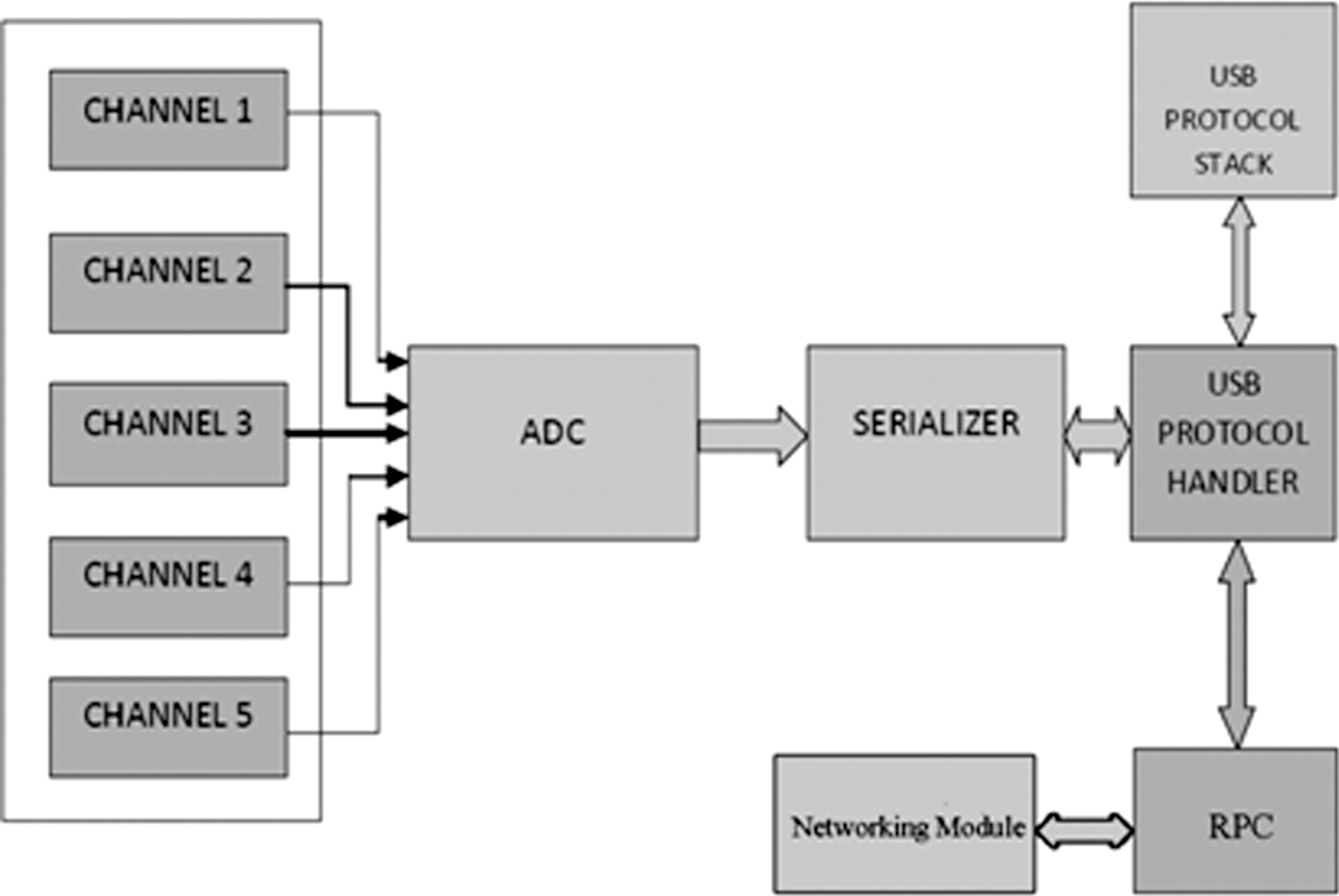
Hardware architecture block diagram of the test node. ADC, analog-to-digital converter.
Hardware Architecture
The ADC block is a multi-input, mixed signal module that sequentially polls each sensor module attached to it. The input signals are preconditioned by the sensing modules to match the input requirements of the ADC. The sensor modules considered includes a thermocouple temperature sensor, a standard analog output ECG probe with integrated noise filtering and conditioning, a standard analog output pulse oximeter, and a pair of test signal inputs to test and calibrate the sampling and also to detect transaction errors.
The DAQ prototype module as in Figure 3 was built around a 5 MHz execution cycle microcontroller with an internal 5-channel 10-bit dual-slope ADC with a conversion time of around 1.46 μs per channel and a universal serial bus (USB) 2.0 high-speed module. The DAQ input/output (I/O) system is a general purpose digital data logger that has a maximum polling rate of ∼196 samples per second per channel (see Results section). The polling strategy is based on the principle of isolated polling wherein only one ADC channel is powered up at a time.
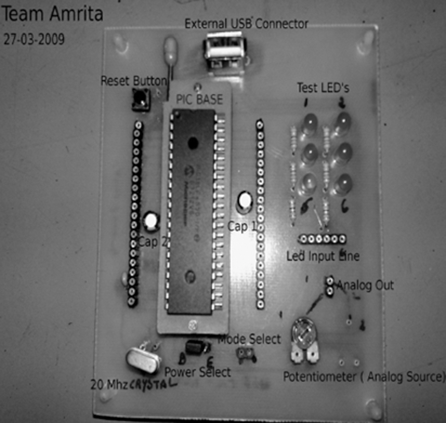
DAQ prototype (Team Amrita). PIC, peripheral interface controller; LED, light-emitting diode.
The DAQ transfers data to the RPC via a standard high-speed USB interface, which provides a maximum data transfer rate of 480 Mb/s. 14 The DAQ is configured as a human interface device (HID) digitizer class device that allows a 1 ms polling frequency. A proprietary subprotocol is implemented (as in Table 1) within the USB HID protocol to maximize the bus traffic utilization. Hence, it eliminates the need for a custom-built device driver, thus enhancing the portability of the system. The USB interface is a host polled system in which the USB root hub is connected to the south bridge of the architecture. 14,15 This results in the stalling of the DAQ, causing the polling to stop until the logged data in the serializer stack is flushed. This can cause data loss if we are to use a regular HID protocol. Estimating the extent of this data corruption and its prevention by the proprietary algorithms eliminates false triggers and thereby improves the reliability of the system. The RPC range considered here included the net-book class computing devices and the OLPC XO-1 that use mobile computing processors, which are IA-32 clones running at subgigahertz speeds. They can host popular operating systems for the×86 architecture, which include Microsoft Windows XP, Linux Distributions, and the Solaris operating system, while running at one-fifth to one-tenth the power consumption of a regular processor and providing up to one-third of its processing performance. 16 –18
Software Architecture
The software system utilizes a hierarchical four-layer approach to effectively transmit the patient data to the monitoring station, which is illustrated in Figure 4. The system layer (SL) handles the USB host protocol. It is responsible for identifying the module upon plug-in and enumerating it as a USB device, allocating communication buffers and addresses and allocating the bus bandwidth for polling in regular intervals. It is also responsible for receiving the raw, protocol-encoded packets from the DAQ and routing it into the allocated device, mapping buffers from where the lower layers can access the data for further processing and network transmission. It relies in the inbuilt driver for USB hosts that comes with all the leading operating systems. Once the device is identified as a generic HID device, the SL routes the data pipes into the allocated device buffers. The required device buffer size is communicated by the DAQ at enumeration. The data-processing layer (DPL) handles the proprietary subprotocol and extracts the channel-specific data from the data routed into the device buffers by the SL. The proprietary data transfer protocol built over the Institute of Electrical and Electronics Engineers (IEEE) standard USB protocol is served in this layer. This layer is responsible for identifying the packet markers and delimiters in the data frame in the device buffers and extracting channel-specific data from it. The data are passed on to the lower layers for further processing and network transmission.
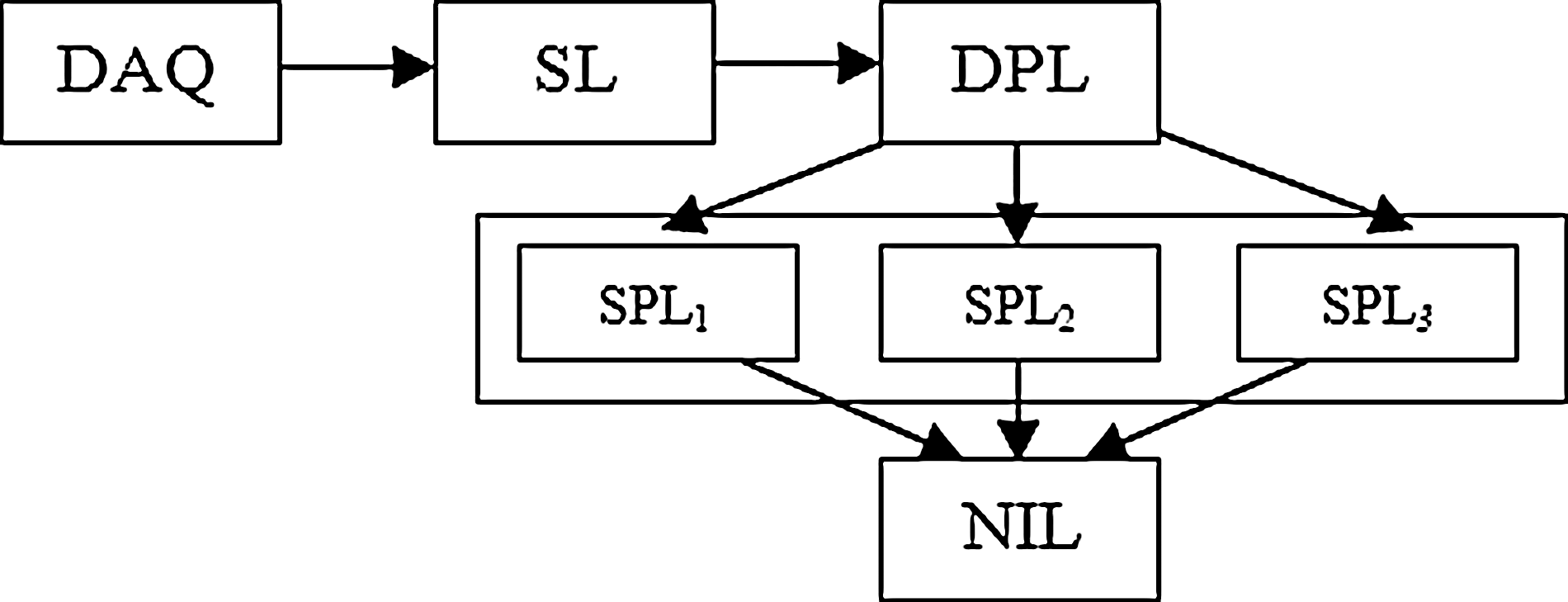
Software layer arrangement. SL, system layer; DPL, data-processing layer; SPL, signal-processing layer; NIL, networking and human interface layer.
The signal-processing layer (SPL) contains multiple scripts that operate on the data extracted by the DPL. Data specific to each channel/sensor extracted from the encoded packet requires different biomedical signal-processing algorithms to be applied onto them so as to extract meaningful and useable information. These scripts combine to form the SPL. The efficient coding of this layer is crucial to avoid bottlenecks in the dataflow path. The RPC comes with a native python v2.5, which is a scripting language. The SPL was implemented using custom python scripts and hence eliminates the need for installing a new scripting language in the RPC. The networking and human interface layer (NIL) handles the networking protocols and graphic user interface (GUI) to interconnect with the monitoring station. The result data from the SPL are communicated to the NIL via individual communication pipes. This helps control data flow rate depending on the polling rate of the sensors. For example, body temperature data can be monitored at a polling rate in the order of seconds, whereas ECG data have to be monitored at a polling rate in the order of microseconds. Adjusting the data transmission over the network based on this polling rate requirement allows a wise use of the available network bandwidth to be used for communication of data of higher priority. This logic is implemented by applying flow control in the data communication path between the SPL and the NIL. The GUI is implemented as a browser page, which doubles up as a sharing platform while locally displaying the results. It also facilitates add-on multimedia application interfaces such as videostreaming and videoconferencing, voice over IP (VoIP), online whiteboards, etc., for collaboration between the data collection center and the remote monitoring station.
Data Transfer Subprotocol
A data transfer subprotocol is implemented within the original USB HID protocol framework. Configuring the DAQ as an HID Digitizer device eliminates the need of a custom device driver, because it is available with most common operating systems. But, it also calls for a low-priority outlook for the device from the system (RPC) side. Thus, the polling priority is possible to be set aside depending on the system task load. 15,19 Hence, the expected 1 ms polling frequency is likely to be effected and a direct, linear data-logging approach cannot be used. Once the system denies the poll request from the SL, the DAQ stalls its operation until either the serialized data are flushed or the watchdog timer expires. In either case, data loss occurs, which can be countered either by using mean value approximation to patch the lost data or by relying on high-level mathematical operations such as predictive projection, 19 which calls for higher computational complexities. This is done at the SPL component level, which monitors unacceptable patches in data. This is assisted by frequent transmission of an internal synchronization clock value that indicates adjacent transfer latency. The HID device configuration permits transfer of 64×8 bits of data per data frame in the full-speed mode. 12 Each channel contributes 10 bits of digitized ADC data. Thus, sets of the new subprotocol frame defined to maximize the bus traffic utilization, carrying a channel identification number, will form the data packet of the original USB HID frame. This subprotocol allows 32 sets of channel data to be transferred every millisecond 19 from the DAQ to the SL. This allows room for oversampling that increases accuracy of the mean value approximation for prediction. Zero padding is needed, as the USB HID packets are formed in 8-bit segments, and is also necessary for the cyclic redundancy check (CRC) calculation. 14,15,19
Buffer Hierarchy
The memory subsystem follows a shared memory mapped I/O model for device as well as interlayer data communication. This allows access of the same data location by different layers simultaneously. But the layer architecture grants each layer either a read or a write access only to the central shared device data buffer. This avoids read/write clash–induced latencies and hence decreases the overall response delay of the system. The SL extracts the encoded device data from the generic USB stream.
The network interface layer hosts a separate set of scratchpad buffers to assemble transmission data packets. These buffers are fed the results of the SPL processing via flow-controlled data pipes. The need for flow control is discussed in detail in the Software Architecture section. The data assembled in the scratchpads are packetized, framed, and transmitted by the NIL.
Network Communication Model For Data
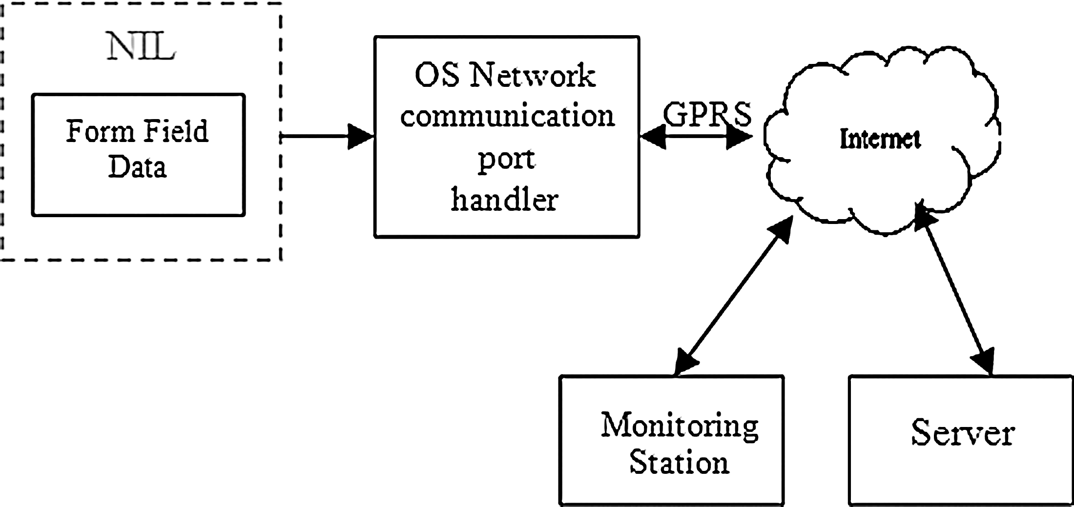
This section briefs the network communication model used by the setup as shown in Figure 5. The scratchpad buffers are periodically accessed by the frame compiler to compile the transaction data. The rest of the communication is handled by the network interface handler software and hardware subsystem of the RPC. The biometric data from an individual RPC can be shared over the network by communicating with the share host server.
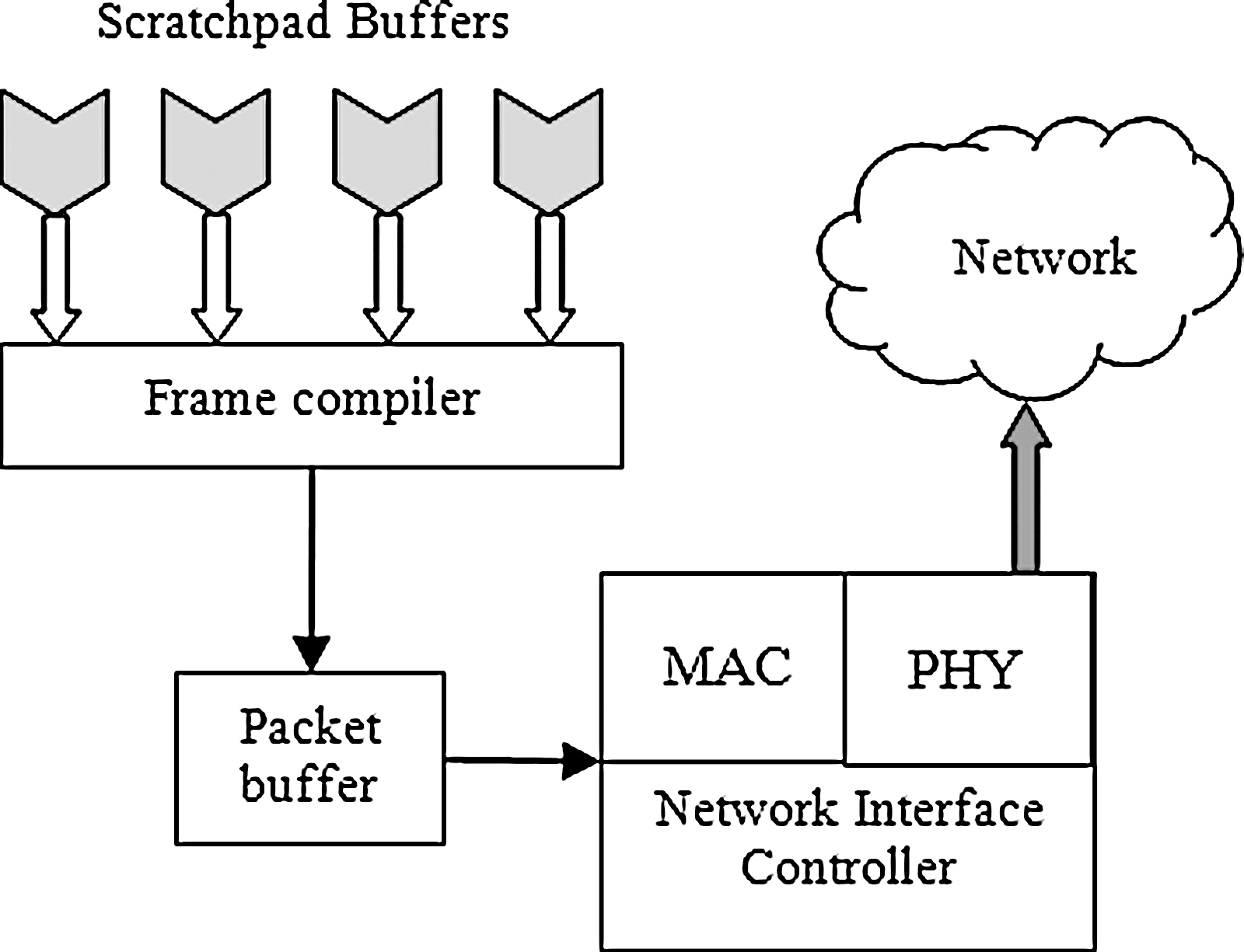
Network interface layer in RPC. MAC, media access controller; PHY, physical layer.
Test Setup and Implementation Details
The RPC for the test setup is an Acer Aspire D250 device with Intel Atom processor (1.68 GHz, 667 MHz FSB, 512 KB L2 cache) and a Mobile Intel® 945GSE Express Chipset (DDR2 400/533/667 MHz). It has a 1 GB DDR2 SDRAM memory interface design and hosts Ubuntu Linux v8.04.1. The SL comes implemented within the device driver set of the Linux kernel. The DPL and SPL components are implemented in Python v2.5. The NIL can be implemented in either Adobe Flex 3.0–based Custom GUI or a Python GTK–based GUI. The test setup and results obtained apply equally well to OLPC XO-1, which hosts an AMD LX700 CPU (433 MHz) with integrated Graphics Processing Unit, AMD CS5536 Companion chip for peripheral I/O, 256 MB DDR SDRAM system memory chip, running at 333 MHz, embedded controller for system monitoring, and 1 GB of NAND Flash memory on motherboard. The DAQ under concern is Peripheral Interface Controller (PIC) 18F4550 Microcontroller, which has support for USB read/write.
The biomedical instruments used for the OLPC biomedical kit, namely ECG, body temperature measurement, and oximeter, were built in-house using low-cost materials and tested for safety. Special care has been taken for making the ECG electrodes shock proof, to facilitate safe handling for children. This includes wooden ladles, which act as the electrodes.
ECG and Heart Rate Monitor
An ECG machine measures electrical activity generated by a heart. Our ECG subsystem used two electrodes to detect this activity. We used TD-142G Vinyl electrodes, which are sponge-gel electrodes and are replaceable. Their signal pickup is much better than the permanent dry electrodes. In addition, having replaceable electrodes is better, because they are more hygienic. To detect the ECG signal, these electrodes were placed under the user's left and right arm. The ECG waveform is obtained from Eindhoven's triangle. Eindhoven's triangle is an equilateral triangle composed of each of the electric dipole vectors, which stimulate the heart. The triangle is centered on the heart and two of its three vertices are approximately located at armpits of a human being. The third is located just below the heart on the left side of the body. Because of this geometry, the ECG signal pickup from under the armpits is very clear. The amplitude of the ECG signal as measured on the skin ranges from 0.1 to 5 mV and the frequency ranges from 0.05 to 130 Hz. 20 Sponge-gelled electrodes were used at the tips of the paddles for the end user to place under their armpits to sense the ECG signal. To make the actual signal usable by a microcontroller, we developed an analog filter circuit. The lead wires from the electrodes are connected to an instrumentation amplifier, which outputs the analog ECG signal. However, before we can use this signal, it must go through a band-pass filter to capture the range of frequencies of heart pulses and filter out high-frequency environmental noise. To eliminate the ambient 60 Hz, we added a 60 Hz notch filter. These filters ensured that the signal from the ECG gel electrodes would be clean. The data flow in our ECG circuit is illustrated in Figure 6.

ECG flow diagram. ECG, electrocardiogram.
To keep the user safe from electric shock, an isolation amplifier is used to isolate the user from the power supply. After the signal has been filtered, the output will be split. One wire from the split will go to microcontroller to calculate the heart rate and the other wire will be sent to the OLPC's GUI via DAQ module to plot the ECG signal. Figure 7 shows the ECG machine made for the biometrics kit.
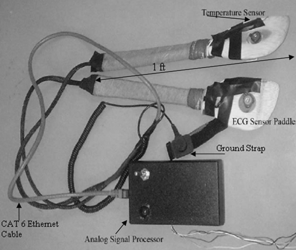
ECG sensor paddles integrated with temperature sensor (Team Austin).
For ease of use and durability, we designed the paddles with integrated ECG and body temperature sensors. These paddles are to be placed under armpits. ECG and body temperature measurements are most accurate at this location on the outside of the body. 21 We implemented the sensor paddles to comply with ethics regulations. These paddles need to be at least 1 foot in length. This was necessary so that children would be able to take measurements without removing their clothing. To achieve this length requirement, we used long, wooden cooking spoons. The spoons were carved with woodworking tools so that sensors and wiring could be placed comfortably inside their frames. ECG electrodes and thermistors were placed on the actual spoon and wires were placed in a grove cut into the spoon handle. To connect the sensors to our circuit box, we used a modified CAT-5 cable to provide a solid connection with the circuitry. This satisfies the requirements set by the physical education teacher, Lynda Levis, from Austin Independent School District, Bryker Wood Elementary (as part of a feasibility study). The paddles include comfortable ground strap. This strap is placed on the right leg. By putting it on, the user completes the Eindhoven's triangle. The sensors are connected to the system by a CAT-6 ethernet cable via an ethernet jack. We used TLC2274 operational amplifiers, which is a low-power, single-supply operational amplifier. For our instrumentation amplifier, we used AD627, which, like the TLC2274, also runs on a single-supply power source and is a very good biomedical instrumentation amplifier.
For safety, all medical equipments that are powered or attached to any device powered by a strong power supply must be isolated. Isolation essentially creates a barrier between power supplies and the users of devices. To create this barrier we used the ADUM1201 digital opto-isolation amplifier manufactured by Analog Devices. Opto-isolation is a technique that transforms an electrical signal into light and then transmits this light signal across a barrier of air. On the other side of the barrier, a photoreceptor decodes the light signal and transforms it back into an electrical signal. In this way, no current can pass the isolation barrier. The last design solution was adding a 2.5 V reference. The power supply of our amplifiers determined the max resolution we could obtain for our ECG signal. For example, using a dual-polarity±5 V supply with a reference at 0 V would allow us to amplify the ECG signal until it reached 5 V in magnitude. As we were constricted to a single 5 V supply, we needed to maximize our resolution by resetting the signal's reference to the midpoint between 0 and 5 V at 2.5 V. We isolated the ECG signal as it passed from the microcontroller to the computer using an isolated RS-232 serial cable. Using the same ADUM1201 chip, we cut RS-232 cable and fed the signal through the isolation barrier. Consequently, our device became safe for use by human beings. The cardiac simulators using function generators were necessary because of issues developing an isolated barrier between the user attached to the electrodes and the earth ground. Without this stage, they needed a method of testing the circuit without hooking themselves up to avoid the hazard.
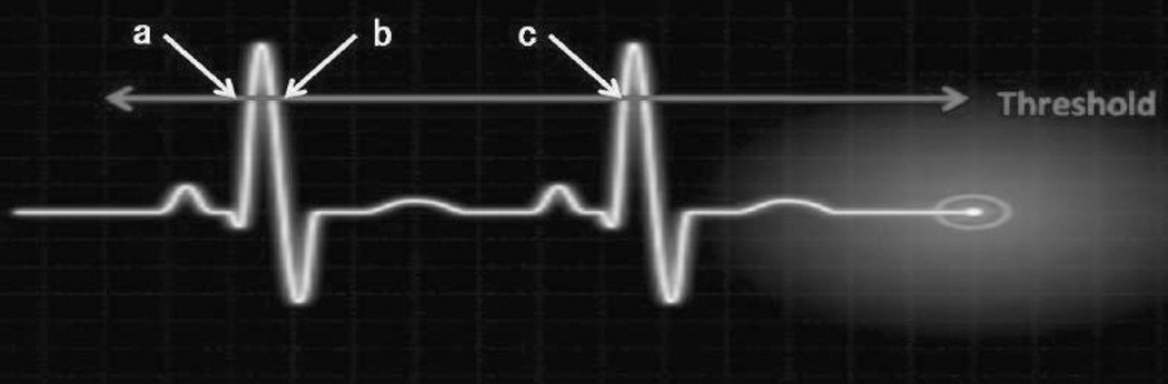
To measure the user's heart rate, we measured the time in between spikes in the ECG signal. The ECG signal is sampled by the PIC microcontroller at 400 Hz. At this frequency, the sampling rate will exceed the Nyquist criterion to avoid signal aliasing and the entire ECG signal will be captured. We programmed the microcontroller to trigger a flag when the signal crosses an ADC threshold. This threshold was placed at the midpoint of the QRS waves of ECG signal. The QRS wave is the tallest peak in the signal. If the value from the 10-bit ADC crossed the threshold during a rising edge, we would take a time stamp. We then measured the time between time stamps. Figure 8 shows the concept to measure heart rate. In this illustration, we measured the time between points (a) and (c). Point (b) is not valid, because it is on the falling edge of the ECG signal. Once the time between pulses is clocked we can calculate the beats per minute and send the calculated value to the GUI.
Heart rate algorithm.
Body Temperature Measure
The user's body temperature will be measured by a thermistor. We have used the Murata NTSA0WF104F thermistor. The thermistor was integrated into two paddles that will be placed in the user's armpits. The armpit is the most accurate location to measure body temperature while being outside the body. 21 The microcontroller will sense the voltage from the thermistor. The 10-bit ADC converts it into an ADC value, and using this ADC value as a key, our software will use a look-up table to calculate the temperature. We employ a look-up table, because the relationship between the ADC value and the temperature is not linear. To ensure accuracy and precision, we limited the range of operation for this subsection. Temperature ranging from 35°C to 40°C is suitable for the body measurements. About 35°C is too cold for body temperatures, and 40°C is too hot. If a child measures at above 39°C, he should be taken to the hospital. As a result of this range, the look-up table had a precision of 0.1°C.
Pulse Oximeter
A pulse oximeter is used to measure the amount of oxygen present in the human blood. 22 The classes of photodiode amplifiers suitable for pulse oxymetry applications are the classical resistor-feedback trans impedance amplifier and the capacitor-feedback switched integrator. This circuit is also common in use with piezoelectric sensor, which also gives out a small current with respond to stimulus. This is the first stage of our circuit. In the pulse oxymeter case, the light shining on a photodiode produces a small current that runs to the amplifier-summing junction and through the feedback resistor. Given the very large feedback resistor value we used (4.7 MΩ), this circuit is extremely sensitive to changes in light intensity. A small capacitor (390 pF) is used to control gain peaking caused by the diode capacitance. The second stage of the circuit is a differential amplifier, which is used to filter out the common noise from the input. The output voltage is in the range of 3.8–4.5 V. For the circuit construction we need a light-emitting diode (LED) excitation circuit and a trans-impedance amplification circuit. LED excitation was done by providing alternating signals from the power pins of the DAQ by using a dedicated polling algorithm for Device Channel 5 of the DAQ module. The LEDs are directly connected to the power pins (Red [R] to Power Pin 1, and Infrared [IR] to Power Pin 2). The power pins are alternatively turned on and off and corresponding readings are taken such that at any given time only one LED is on and the amplifier outputs the corresponding voltage. The data are packed by the DAQ firmware using two separate channel subframes, with channel numbers 51 and 52 for Red and IR, respectively. This is identified by the data-processing scripts and data are correspondingly extracted and fed to the signal-processing scripts as Red and IR channel data.
The ratio of R and IR (R/IR=ln [ImaxRed/IminRed]/ln [ImaxIR/IminIR]) was computed, where • ImaxRed is maximum amplitude of voltage logged from Red LED in a single heart beat pulse cycle, • IminRed is minimum amplitude of voltage logged from Red LED in a single heart beat pulse cycle, • ImaxIR is maximum amplitude of voltage logged from IR LED in a single heart beat pulse cycle, and • IminIR is minimum amplitude of voltage logged from IR LED in a single heart beat pulse cycle.
The R/IR is compared with a “look-up” table (made up of empirical formulas) that converts the ratio to an SpO2 (oxygen content in the blood) value. Typically, an R/IR ratio of 0.5 equates to ∼100% SpO2 and a ratio of 1.0 equates to ∼82% SpO2, whereas a ratio of 2.0 equates to 0% SpO2. The main circuit components required for the oximeter circuit are Red LED (660 nm), Infrared LED (910 nm), a photo detector diode, and LM311 amplifiers available in local electronics shops. Figure 9 illustrates the actual oximeter implemented in hardware for the biometrics kit.

Oximeter circuitry hardware (Team Amrita).
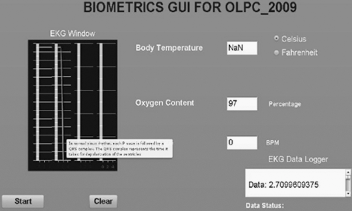
In the prototype, USB frame data are periodically logged onto the character device file local to the XO Laptop. The local SPL implemented in python reads frame data, performs data processing, and produces channel data corresponding to each ADC channel. The modified DAQ module with support for five ADC channels is shown in Figure 10. The role of the GUI is to periodically update the GUI data boxes with the new available data. The graphical user interface prototype as shown in Figure 11 was implemented using Adobe Flex 3.0, which generates a “.swf” (flash file format) on compiling that can be copied to any test machine. The prototype was later improved by implementing the same using shared memory model, thus improving the data read/write latencies as in case of text file approach.

DAQ final assembly plug-in module (Team Amrita).
GUI prototype screenshot (implemented in Adobe Flex 3.0). GUI, graphic user interface; OLPC, One Laptop per Child.
The inbuilt feature of the XO Laptop allows it to communicate to other XO Laptops in the vicinity using Wi-Fi protocol and enables sharing of test data results to multiple clients using browser mode. This serves our final goal of being able to communicate and integrate the health learning tool to a wider number of students who may not necessarily have individual biometrics kit.
As a learning tool that encourages students to explore further, we have devised the kit in such a way that any measurement devices (biometric components) developed by students in future can be integrated into the same by simply logging into administrator mode and selecting appropriate ADC channels along with application device–specific signal-processing scripts. This can be done using Windows SimpleHIDWrite 23 software. Hence, our biometrics kit serves as a learning as well as informative platform for children.
The USB can provide a maximum current of 100 mA while the PIC can source/sink a maximum of 25 mA. The extra current could be also used to drive other biometric components and hence called bus-powered components. This eliminates extra power sources for driving the biometric devices. The oximeter prototype was successfully implemented using the bus-powered scheme as shown in Figure 12.
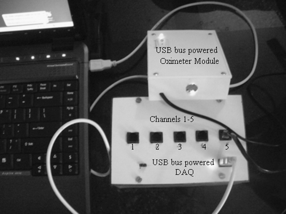
Test setup of biometrics kit (bus-powered DAQ and bus-powered oximeter).
Cost Considerations and Future Enhancements of the Biometrics Kit
We anticipated our prototype cost at $438.33 based on initial cost analysis study. This cost did not take into account the OLPC, which costs $208.00. The DAQ module consisting of the PIC 18f4550 costs $45 and the total printed circuit board (PCB) purchase and fabrication costs around $10. The ECG circuitry costs $45.49, thermistor circuitry costs $45.82, and the oximeter circuitry costs $21.5. At the conclusion of our project, we accumulated a prototype cost of $375.81 including the cost of the OLPC. In comparison to a normal biomedical setup with the same functionalities, the current cost of the kit can be anywhere around $1,000–$2,500 in market. The cost reduction has been possible mainly because of the use of an RPC, supplemented by low-cost design strategies mentioned earlier.
As the project work is done on an open source platform (Linux) and the custom software used is also an open source language (Python), the biometrics kit can be easily integrated to existing healthcare networks/organizations such as the Continua Health Alliance. The basic communication protocol used in our project is the USB, which is a global standard and hence adds to the interoperability of our biometrics kit. Moreover, the OLPC XO Laptop also supports a WIFI Connection, which can help connect the individuals directly to the doctor via similar networks.
As far as safety is concerned, there is a minimal small risk of a slight electric shock while using the OLPC biometrics kit. This only occurs if the user is not isolated from the power supply (e.g., a wall outlet) or if there is a substantial current leaking out of the electrodes. We have taken precautions to eliminate both risks. The kit is designed so that the user is only connected to isolated power and leakage current is below 10 μA, a safe limit. 20 However, our concept of the OLPC biometrics kit has a lot of room to grow in the future. This kit can be enhanced for functionality in critical medical cases. Although our overall system prototype costs roughly $370 to implement, once mass-produced the kit could be a cheap and interesting learning tool across the globe. From here, the concept can continue to grow into the medical field with a few adjustments to make our design concept even more inclined to critical medical grade. The cheap cost of the OLPC could one day provide biomedical instrumentation to the medical field throughout developing countries. If anyone were to take our concept to this level, it could produce ECG machines costing only a few hundred dollars range as opposed to a few thousand.
The current paddles are connected to the PCB box via CAT-5 ethernet cable, and the cable is providing stable and accurate data transmission. However, especially as an educational tool for children, we believe that having a wireless paddle would be convenient and free of hassle for the users. To make the paddles wireless, a wireless signal transmitter would be implemented onto the paddles themselves. The signal will go through the transmitter and deliver data to the microcontroller for signal processing. By doing so, this will also guarantee more safety for the users as they will not be connected to the external powers supply. Although we do anticipate that the wireless transmitters will generate an excess amount of noise, we believe that future technology will be able to solve the issue. We also hope that the project will be modeled toward the medical field instead of purely using it for educational purposes. To do so, our team has a few recommendations for the transition: increase system accuracy and resolution, provide hospital grade power isolation, enhance the GUI, and keep cost of system at minimum. If this transition can be made, we believe the biometric kit for the OLPC can be used to help doctors and aid workers in the third world. Currently, the GE MAC 400 is marketed to doctors as a mobile and cheap ECG machine. The GE MAC 400 costs $1,500. We believe that the biometrics for the OLPC can be manufactured for a cheaper price and provide medical-grade accuracy. We believe that the biometrics kit has a tremendous potential in the medical theater.
Results
The results obtained from the various tests proving the feasibility of the approach is elaborated in the following text.
Data Polling, Transfer Latencies, and Errors
A sine wave input is used to test and validate the system at large. As majority of the biometric signals from any sensor can be simulated by changing the frequency of the test wave, it proves useful to test all boundary cases of input data while taking care of the hassles of generating varieties of biomedical signals. The sensors are extensively tested and validated in a different platform (Windows XP; Microsoft) and proved for compliance with the system.
The sine wave structure would also help us debug the basic data integrity issues in the system because of its single frequency nature.
A sine wave is fed to one of the channels, passed through the software layers, locally collected, and tested for signal integrity at reconstruction. This will validate the impact of data quantization and information loss during digitization in the final result. The core USB traffic is kept at a maximum by connecting interrupt type and bulk devices at three other available ports and the DAQ at the fourth port. This would give the worst case scenario during an input frequency sweep to simulate varying inputs.
Sine waves of frequencies ranging from 10 to 435 Hz (practical range of normal biomedical signals) were used as input to the single-channel DAQ module. The sampled, digitized data were sent through the USB to the local XO machine. The data values were extracted from a logged text file and reconstructed in the test RPC using MATLAB 7.4v to check the integrity of the reconstructed signal with respect to the original test signal. The test results from the reconstruction validated the working of our system for normal biometric signals. The frequency content of the input sine wave was verified by using fast Fourier transform. The worst case result came out as the input frequency hit 435 Hz as shown in Figure 13. The spectral analysis of the data collected at the NIL, after the corresponding SPL component performing a mean value approximation to reconstruct data patches and a loop routine to simulate processing latency, shows noisy peaks. As a result, the envelope of the reconstructed signal starts to show distortions even after mean value prediction and also the small downward peaks show the values that cannot be approximated within accurate range. These data are collected before the network transmission and show the maximum input frequency per channel that can be effectively used for transmission via the network.
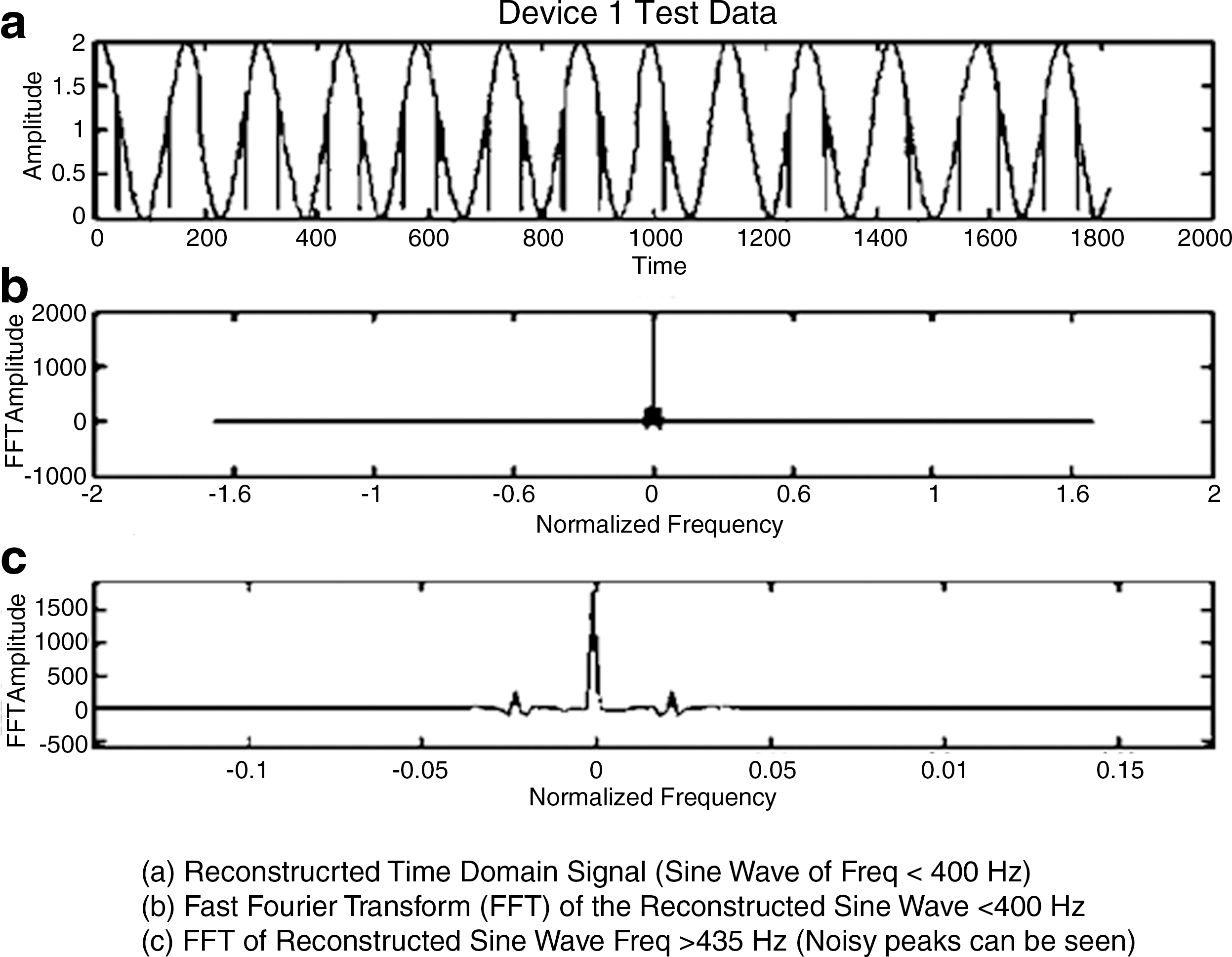
Worst case results at 435 Hz (testing done in MATLAB).
Network Transfer
The NIL hosts a GUI for displaying the results in the local center. It is a field-based Web form implemented in Adobe Flex 3.0 and displayed using standard Web browser software with added certificate-based file access and modification privileges. The data from the SPL are directly communicated to the program fields relevant to each SPL component through the flow-controlled buffer interaction pipes. This acts as local display platform for the processed data. The browser page content is shared with the monitoring station using a standard browser sharing program. Real-time nature is preserved by setting process priority flags and keeping the amount of data to be transferred at a minimum. 24 The NIL utilizes a client server model for data transfer to the monitoring station as illustrated in Figure 14.
Network interface setup.
Software Testing Results
The EKG wave running display was implemented in Adobe Flex and the waveform produced was compared and validated using MATLAB v7.4. A triangular wave was applied to Channel 1 of ADC, digitized by the DAQ, and reconstructed using the ECG wave window of XO Laptop as well as MATLAB v7.4. Another interesting result obtained was that, while a text-based approach proved to be slower in a conventional laptop (1.6 GHz) owing to the latency in read/write cycles, the OLPC (433 MHz) emerged a clear winner in terms of the amount of data that had been logged on. The former logged on a mere 30 data values in 5 s, whereas the latter logged on a staggering 450 channel values in the same time frame. This 15 times increment in data values can be attributed to the simple fact that OLPC has no secondary memory and hence the read/write approach does not hamper to a greater extent, the speed at which USB writes the data into the device file while the SPL tries to read the data written. This result is good news, given that students with lesser exposure to advanced software programming techniques such as Shared Memory Approach can write custom SPL scripts using basic text read/write approach and produce commendable results for noncritical data instruments (ECG requires more values for wave reconstruction while temperature polling can be less frequent, because variability is lesser).
Summary and Conclusions
An effective model for remote patient monitoring over the Internet using a generic RPC and a plug-in DAQ module was proposed and analyzed. The approach addresses the current trend in localization of telehealth centers due to high cost of implementation, which reduces the scope of effective use of the technology. An RPC is a low-cost clone of the personal computer functioning at reduced speed and power. On using an operating system with the “fancy features” striped off, the real-time processing efficiency of the system is increased. This is complimented by the hardware DAQ that effectively uses the IEEE USB protocol for data communication. The use of a generic USB protocol enhances the portability and versatility of the DAQ. Software for data processing and interface handling was developed and tested in open platform language python. The system has been tested and proved for data integrity and stability using standard test methodologies. The proposal to use the World Wide Web network backbone has been also validated through data analysis.
Footnotes
Acknowledgments
This work is part of a collaborative effort between the students of Amrita Vishwa Vidyapeetham Amritapuri Campus and University of Texas at Austin, carried out between September 2008 and May 2009. The authors thank UT Austin for the support and for making such collaboration possible. Special thanks to Dr. Vicki Almstrum for her support and guidance throughout this project. The authors also thank Dr. Krishnashree Achutan of Amrita University, the overall coordinator of the UT project, for making this endeavor possible. The authors also thank the Amrita E-Learning Research Labs for providing the OLPC kit for conducting the proposed work. Special thanks to Jayaraj Poroor of Amrita Research Labs as well as Chitra S. Pai and Kamal Bijlani of Amrita E-Learning Research Labs for their valuable inputs throughout the duration of the project.
Disclosure Statement
No competing financial interests exist.