
Abstract
Introduction
In the state of California, the law requires only one employee to be on duty for every 100 residents in residential care facilities caring for the elderly. Thus in a senior center, a centralized vital signs monitoring station that collects vital signs from all residents and gives warning upon abnormal activities would be very helpful.
Vital signs are measures of various physiological states that are used to assess the most basic functions of the body. The four standard vital signs that are used in most medical settings are the body temperature, heart rate (HR), blood pressure, and respiratory rate. The HR is the easiest of the four signs to measure and can give a rough idea of a patient's cardiac status. 1 Many companies, like Polar and Garmin, make HR monitors, but these are mainly for fitness use. Most such devices come with a chest harness and watch. The watch receives and analyzes the signals sent from the harness and shows the resulting HR. Some other devices have no chest harness, 2 but instead the users put their finger on a tiny metal plate on the watch to get a reading. However, the HR monitors designed for fitness use are not suitable for long-term, centralized monitoring in places like a senior center for the following reasons. First, the chest harness of a HR monitor for fitness needs to be moistened to get the reading, which is rational for fitness usage but not for the elderly in a senior center. Second, the chest harness could get loosened easily during sleep because of body pressure. Finally, the fitness HR monitors are designed for personal use and not suitable for centralized monitoring.
Design Goals
In order to address this issue, we design a centralized HR monitoring system. The main purpose is for the nurse station to be able to monitor the health condition of the residents in a senior center. The design goals for the system are as follows: 1. The system will alarm the control center of any acute abnormal cardiac events. 2. The sensor should be comfortable for continuous wearing. 3. The system should not affect the daily activity of the wearer. 4. The sensor should collect data reliably and then transmit the collected data reliably, wirelessly to the control center. 5. The battery of the sensor should last for more than 96 h. 6. The wireless radio spectrum should co-exist with existing WiFi so no network infrastructure has to be changed. 7. The sensor should be light and water resistant. 8. The design should be user-friendly to both the wearers and the managers. No complicated operating procedures are needed.
To satisfy the design goals, knowledge of body area networks, wireless sensor networks, and micro-electromechanical systems is needed, and some related previous studies are discussed below.
Related Work
Chen et al. 3 discussed how to integrate body area networks, wireless sensor networks, micro-electromechanical systems, and possible applications in their work. Chipara et al. 4 deployed a wireless sensor network system to monitor patients' HR and oxygen saturation continuously; their sensor hardware was buggy, with 12 out of 41 sensor nodes having less than 50% up time. Aminian and Naji 5 proposed a wireless body-area sensor network (WBAN) system that can monitor a patient's motion, blood pressure, and HR using different sensors. The data from these sensors are collected by a coordinator and uploaded to a database server, with the WBAN being simulated in OMNet++ in their work. Yuce 6 implemented a prototype of vital signs monitoring WBAN and proposed using the radiofrequency reserved for medical purposes. Zhu et al. 7 proposed an method for monitoring HR, respiration rhythm, and body movement during sleep. Finally, Ullah et al. 8 undertook a thorough survey of research into physical, MAC, and network layers for WBAN, whereas Singh and Jain 9 carried out a similar review on wireless sensor types, communication modules, and applications for healthcare.
However, all these prior works are implemented in either simulators or prototypes. None of them was deployed in a real-world environment for monitoring HRs continuously for a large group of users in a long period of time. On the other hand, 63 seniors in a senior center have used our system for over a year. To show that our system has met all our design goals, we ran several long-term tests on the system and then proposed some solutions to the problems that were found, as described later in this article, before deploying it in a senior center. The system has been up and running for more than a year now and has achieved both high system availability and user satisfaction.
Materials and Methods
System Structure and User Interface
The structure of our system is shown in Figure 1. The user wears a ring probe that can detect the waveform of the user's pulse. The waveform is read by the sensor, which consists of a microcontroller and a wireless radio transmission unit. The sensor takes the waveform received from the ring probe and uses it as the input to calculate the HR. The calculated HR is then sent to the receiver wirelessly using the ZigBee 10 radio protocol every 3 s. After receiving the packet, the receiver can forward it to any destination over the Internet with the onboard Ethernet port and transmission control protocol/Internet protocol–enabled chip. In our case, the HR data are forwarded to one designated database server. Our receiver can operate independently, without a computer, because the onboard Ethernet chip has socket programming ability. Managers and caregivers can thus watch the real-time HR and access the historical events and records using any computer with Internet access, using the user interface shown in Figure 2. We take the finger ring form proposed by Rhee et al. 11 as our basic design idea.

The structure of the heart rate monitoring system.
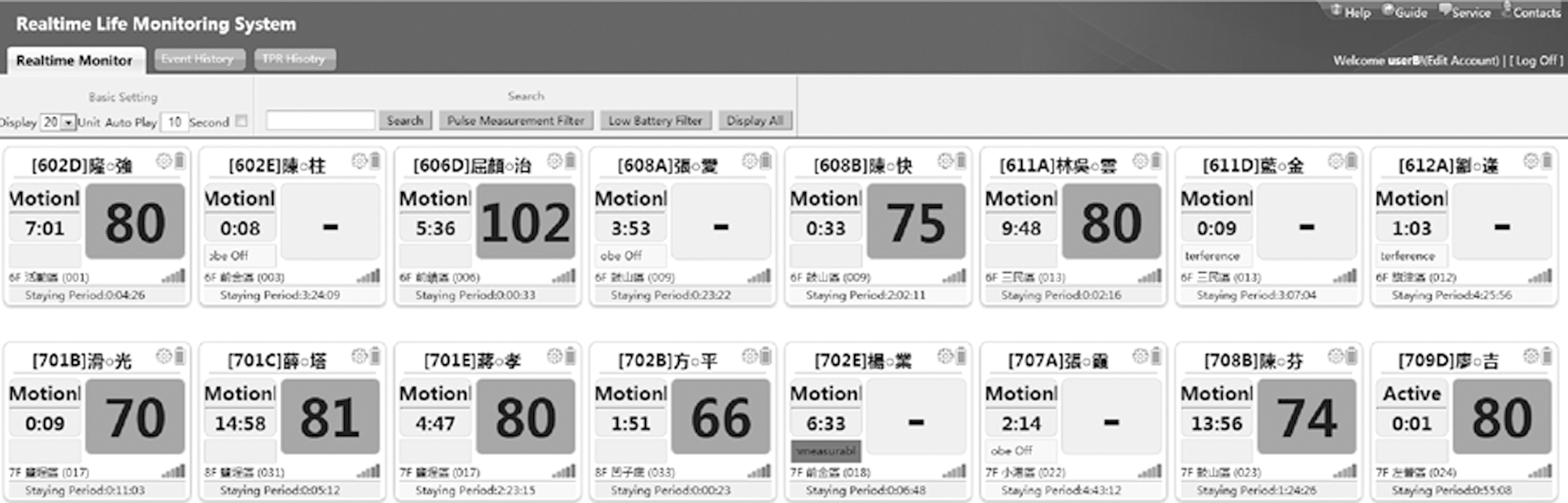
The user interface of the heart rate monitoring system.
Some physicians are involved in the design phase of the system. We decided to monitor only HR but not oxygen saturation because a doctor can decide if the wearer needs additional care or not simply by the variation of HR. Also, by not monitoring oxygen saturation, a tremendous amount of battery power is saved. To satisfy design goals 2 and 3, the finger ring–type sensor is preferred over the most commonly used fingertip probe given that the ring type does not pressure the finger as much and will affect the finger touching movement the least. A fingertip probe is bulky and makes even typing on a keyboard or grabbing a pen difficult. A well-designed finger ring probe can detect pulses accurately without these problems.
Design of the Finger Ring
As shown in Figure 3, on top we used the existing commercially available, off-the-shelf model as our first-generation ring probe. It has a thin belt that is difficult to loop through. It uses the RS-232 interface, which makes it difficult to cut down the sensor size. Most important is that the light-emitting diode and the photodiode are placed on two different surfaces and thus create different angles for different finger sizes, which results in inaccuracy in the ring probe's HR measurements. The straight cable connecting the sensor and probe bends when wearing and becomes a hook that traps things in users' daily life. It was changed to a spring type since the second generation.

The finger ring probe was made in a rounded shape in our second-generation device. It fits the finger better; thus there is no gap between the probe and the finger. In the first-generation device, when the wearer is exposed to sunlight, the photodiode reading reaches its maximum because of the strong daylight received through the ring gap, which makes it impossible to calculate HR.
We also changed the probe interface from RS-232 to micro-USB, but two problems remain to be solved. First is the direction of the micro-USB plug being parallel to the direction in which the probe will be pulled. As a result, the probe is pulled off by the wearers all the time. The second problem is the color of the buckle of the finger ring. It is solid gray in the second-generation device, which blocks the light-emitting diode light when the wearer takes it off. The device is programmed to distinguish whether the probe is worn or not by detecting how much light is received by the photodiode. The solid color buckle can block the light-emitting diode light if the wearer takes the probe off but accidentally bends the buckle. This creates an illusion that the user is still wearing the ring probe, but no HR can be measured because there is no signal received. This, in turn, will create a flat line in the measured signal, which will be calculated as HR 0 and set off the most serious alarm, just because of a bent buckle.
For the design of our third-generation ring probe, we change the buckle color to transparent. The micro-USB plug was also moved to the side of the sensor. We changed the look as well. The dissolving color with the nice small red-cross button for emergency call makes the device looks professional and reliable, which is actually a very important step in our practice to motivate the users to wear it continuously.
Design of the Sensor
Both the sensor and the receiver are based on the Berkeley TelosB mote platform 12 and run our own embedded software. However, the sensor is modified to work with the ring probe, whereas the USB port on the receiver is changed to an Ethernet port. The hardware architecture for the sensor and receiver is shown in Figure 4. The probe first detects the strength of the pulse signal and then sends the signal to the sensor. The signal is a very small current, so it is run through a power amplifier before being passed to an A/D converter. Note that the range of the amplifier has to be large. This is because when used in the real world, the lighting may range from pitch darkness during the night to strong sunlight when the user is outdoors. In addition, the condition of the users' skin could vary a lot, from thick and coarse to thin and smooth. We adjust the power amplifier dynamically through embedded software, so that the amplified signal suits the range of the A/D converter. The A/D converter converts the analog signal it receives into a digital one at 64 Hz.
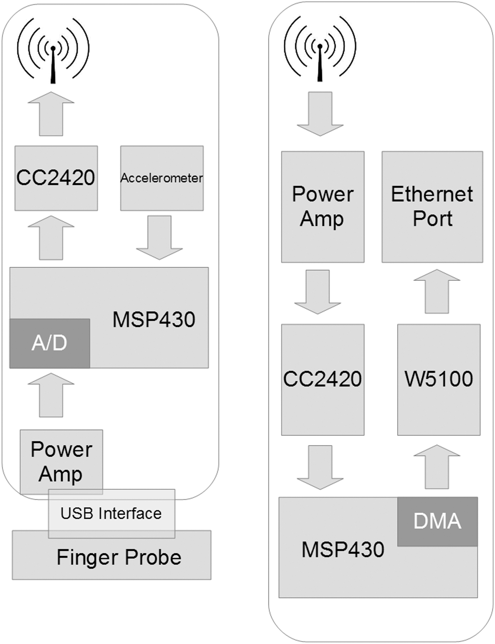
The hardware architecture of
Several prior studies have discussed the pros and cons of different wireless modules, 13 such as Bluetooth 4.0, 14 WiFi, and ZigBee. We decided to use ZigBee because of its roaming ability when the user moves from one receiver to another, as well as battery life. Our sensor averages 5 days of battery life using a 550-mAh rechargeable battery with the ring probe. An accelerometer is added to the circuit board to monitor the motions of the user. An warning will be sent when too much motion is detected, making the HR measuring impossible. The sensor is worn like a watch on the user's wrist, as shown in Figure 5. The ring probe is usually put on the little or ring finger, as the users reported that these are the most comfortable positions.
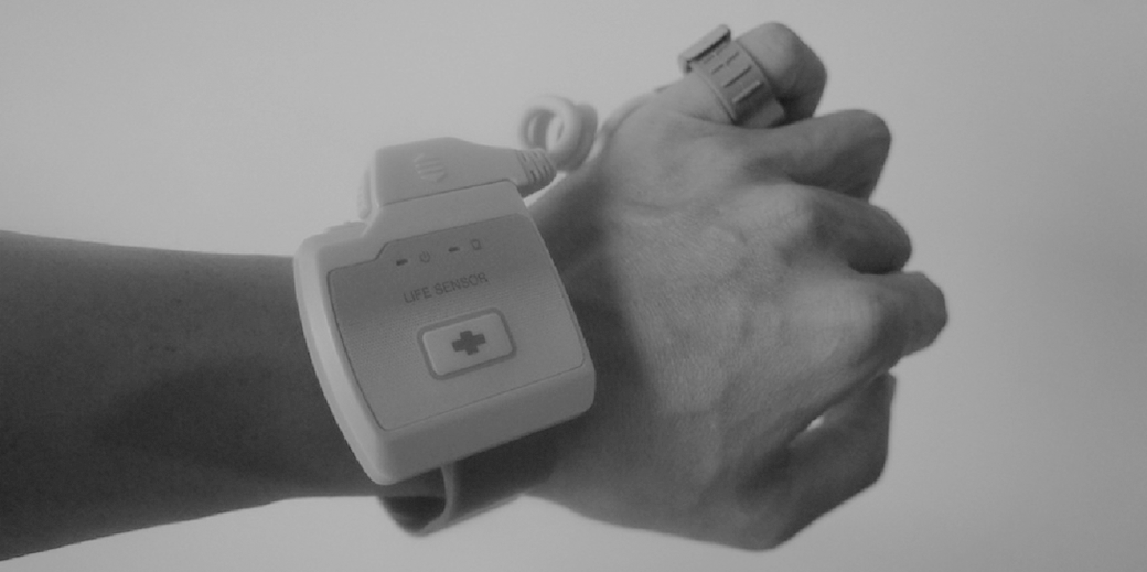
The vital sign motoring sensor in action. The green light-emitting diode on the left blinks every 3 s to indicate the power is on and a packet is transmitted. The orange light-emitting diode is turned on when the battery is low. The button with the red cross symbol is for the emergency call.
The Receiver with an Ethernet Port and Power Over Ethernet
The receiver receives data packets from sensors wirelessly and forwards them to the data sink, which is our database server. Although it is common to run multihop routing protocols to forward packets to the sink for outdoor deployments, 15,16 we found in practice that a ZigBee-based ad hoc network is not stable enough to achieve the reliability we need. We thus use an Ethernet link to forward the data from the wireless receiver to a sink. Finally, to avoid the difficulty of finding a power outlet for the receiver, we use a power over Ethernet chip (TPS23750 from Texas Instruments 17 ) and WIZnet W5100 18 for Ethernet operations. A 64-Hz timer triggers the photodiode reading event on the sensor, as shown in the Appendix (Fig. A1) for Function 1. The Send-Packet() function is called every 3 s to send the HR calculated, as shown in the Appendix (Fig. A2) for Function 2. Any receiver hearing the HR packet will pick it up and forward it to the database server.
Results
The Calculated HR Validation
Our HR calculation algorithm is based on the Pan–Tompkins algorithm for QRS detection. 19 We collected waveforms generated by the finger ring probe from patients in a hospital with different ages, sexes, and diseases for 3 months before using it in the senior center. Several adjustments were made to the original algorithm to be able to generate reliable and accurate HR readings. We validated our results by comparing them (from different fingers) with the waveforms captured by a high-end commercial electrocardiogram sensor (Nellcor NPB-40 20 ). Ten subjects were chosen for this validation process, and the differences between the Nellcor NPB-40 and our device are on average within ±3 beats/min (BPM).
We also tested our device using a pulse simulator, which generates stable pulses between 30 and 240 BPM. Our device is able to correctly calculate the simulated HRs within this range with 100% accuracy. Figure 6 shows the verification process of calculating the simulated HR of a cardiac arrhythmia HR patient because this type of waveform is generally the most difficult to calculate correctly. The diamond-shaped dots (STD) are the pulses generated by the simulator, whereas the square dots (PKT) are the results computed by our sensor device. The diamond-shaped and square dots mostly overlap for the simulated HRs between 30 and 240 BPM, which suggests our calculated HRs are either identical or very close to the generated ones. The triangle-shaped dots (PNT) are the adjusted results after filtering the signal noise and the final HR readings shown on the monitor station's user interface (as shown in Fig. 2). Most existing HR oximeters also adopt similar adjustment algorithms to prevent noise from triggering false alarms.
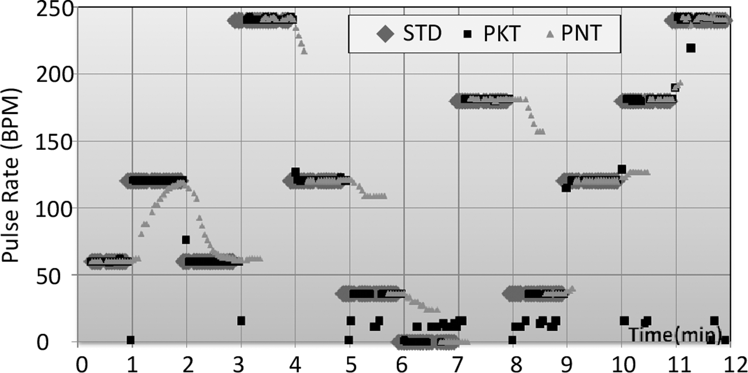
The verification process of simulating cardiac arrhythmias. Diamond-shaped dots (STD) are the signal heart rate. Triangle-shaped dots (PNT) are the heart rate shown in our user interface. Square dots (PKT) are the results computed by our sensor device. BPM, beats per minute.
The System Reliability
We calculate the System Availability as the probability the system is operational at any given time. This is important because the manager can know the wearer's status based on the packet received. Chipara et al. 4 suggested System Reliability should be calculated in two parts: Network Reliability and Sensing Reliability. However, they have relatively low Sensing Reliability, at 80.55%. In our system, the sensor is not able to calculate the HR under some situations (e.g., when the sensor is being shaken). Different types of messages will be sent according to the status of the sensor, listed in Table 1. If the packet received is not of HR type, the manager can dispatch a caregiver to solve the issue. Our system availability averages 99.48% in a year-long deployment. In total, 32 seniors are wearing the sensors at the time of writing, 24 of whom have suffered from a stroke or have Parkinson's disease.
Packet Types of the Messages Sensors Send to Receivers
Discussion
Unfortunately, during the year-long deployment of the system, one senior passed away, while wearing the ring probe, in January 2013. Although our system did catch the event of irregular HR activity and set off the alarm, this occurred in the middle of the night while all the task force were off duty, and so the nurse station only dispatched assistance 10 min after the alarm was set off.
The system has run smoothly throughout its deployment, and 17 seniors have worn the sensors from May 2013 until early February 2014, at the time of writing. We spent 27 days, 2 h per day, in the senior center to verify whether or not the system was able to detect the events it was designed for. During the 54 h we spent there, 10 alarms were set off. Seven of these were true alarms, indicating irregular HR activity, two were due to the ring probe being too loose, and one was because the caregiver had turned the senior over in bed.
Although they were initially skeptical of the system, the caregivers changed their attitudes after the death reported above, coming to see it was an effective and important tool that can alert them whenever an HR-related emergency occurs. The nurses and managers at the senior center were very enthusiastic about the system right from its initial deployment because they felt that it was easy to use and provided valuable information. Because the system involves no complicated settings or wiring, nurses only need to enter/delete the names of incoming/leaving residents and click on alarm dialogs to confirm that such events have been taken care of. The system overhead is also minimal for users and managers because it is entirely plug-and-play. As Davis et al. 21 have suggested, we fit the technology within the primary care workflow.
Conclusions
The results of the year-long deployment show that the wireless group-monitoring system developed in this work is viable for use within a designated area. Compared with previous studies that carried out similar investigations, 22,23 our deployment was longer in length and larger in scale. The usage patterns we collected are thus close to the actual patterns of the patients' daily lives, and thus the lessons learned in this work are more valuable than would be possible with a more limited deployment. Our system is still up and running and achieves an average system availability of 99.48%. In the future, we plan to use the waveform data collected by the finger ring probe to detect potential diseases. Figure 7 shows the mean HR variations in March of 2013 for two users. Subject 711E generally had a lower HR variation throughout the month, and we later found that this person had previously been diagnosed with heart disease. One important lesson we learned during this deployment was that, like any other technology, the design of mobile medical devices should be user-centered. Such devices should thus be comfortable to wear, be convenient to walk around with, have a long battery life, and be able to automatically upload the data that are collected. If these design criteria are met, then it is more likely that users will be willing to use the technology, and even grow to love it.

The mean heart rate variations (HRVs) in March 2013 for two senior subjects. The solid line is the mean HRV of patient number 710A; the dotted line is the mean HRV of patient number 711E.
Footnotes
Disclosure Statement
T.-Y.S. is an employee of Taiwan Telemedical Device Company. J.-H.H., P.R., and K.-c.L. declare no competing financial interests exist.