




Abstract
Objective:
This study focuses on developing bioactive piezoelectric scaffolds that could deliver bioelectrical cues to potentially treat injuries to soft tissues such as skeletal muscles and promote active regeneration.
Approach:
To address the underexplored aspect of bioelectrical cues in skeletal muscle tissue engineering (SMTE), we developed piezoelectric bioink based on natural bioactive materials such as sodium alginate, gelatin, and chitosan. Extrusion-based 3D bioprinting was utilized to develop scaffolds that mimic muscle stiffness and generate electrical stimulation (E-stim) when subjected to forces. The biocompatibility of these scaffolds was tested with the C2C12 muscle cell line.
Results:
The bioink demonstrated suitable rheological properties for 3D bioprinting, resulting in high-resolution composite sodium alginate–gelatin–chitosan scaffolds with good structural fidelity. The scaffolds exhibited a 42–60 kPa stiffness, similar to muscle. When a controlled force of 5N was applied to the scaffolds at a constant frequency of 4 Hz, they generated electrical fields and impulses (charge), indicating their suitability as a stand-alone scaffold to generate E-stim and instill bioelectrical cues in the wound region. The cell viability and proliferation test results confirm the scaffold’s biocompatibility with C2C12s and the benefit of piezoelectricity in promoting muscle cell growth kinetics. Our study indicates that our piezoelectric bioink and scaffolds offer promise as autonomous E-stim-generating regenerative therapy for SMTE.
Innovation:
A novel approach for treating skeletal muscle wounds was introduced by developing a bioactive electroactive scaffold capable of autonomously generating E-stim without stimulators and electrodes. This scaffold offers a unique approach to enhancing skeletal muscle regeneration through bioelectric cues, addressing a major gap in the SMTE, that is, fibrotic tissue formation due to delayed muscle regeneration.
Conclusion:
A piezoelectric scaffold was developed, providing a promising solution for promoting skeletal muscle regeneration. This development can potentially address skeletal muscle injuries and offers a unique approach to facilitating skeletal muscle wound healing.

INTRODUCTION
According to the Global Burden of Disease 2019 report, musculoskeletal injuries affect 1.7 billion individuals globally, representing nearly one-quarter of the world’s population. 1,2 These conditions account for about 17% of global disability-adjusted life years lost, translating to a vast economic burden estimated at around $1 trillion annually. 1,2 In the United States alone, over 57 million people experience disability due to musculoskeletal injuries, contributing to 20% of all disability claims. The resulting economic impact in the United States exceeds $213 billion annually, encompassing direct medical costs, lost productivity, and potential disability payments. 3
Skeletal muscle possesses an innate ability to repair itself in response to minor injuries, thereby preserving its critical functions. However, in major muscle injuries such as volumetric muscle loss (VML), where a significant portion of the muscle tissue is lost, the body’s innate regenerative potential is significantly compromised. 4 Such major injuries lead to excruciating pain, poor muscle recovery, and permanent functional impairments, considerably impacting patient mobility and quality of life. 5 The most current surgical technique is muscle flap transfer, where muscle tissue is harvested from a healthy site and transplanted to the injured site. 6 Even though this technique can significantly help reduce early complications, the therapeutic efficacy in the long term is challenged. For instance, a lack of host–tissue integration and donor-site morbidity leads to poor functional recovery or even amputation. 7 Acellular scaffolds have been developed to address some limitations, but only decellularized extracellular matrix-based scaffolds are currently used. 8 Unfortunately, these scaffolds have clinically shown a lack of reinnervation and poor functional recovery in the restored muscle. 9 Moreover, the major disadvantage is forming fibrotic tissue instead of functional muscle due to delayed muscle formation (in the case of acellular scaffolds). Cellular therapies, such as myoblast transfer and scaffold repopulation with cells, have emerged as promising strategies for repairing and muscle regeneration. 10 These approaches involve transplantation or introducing muscle precursor cells into damaged muscle tissue to facilitate tissue restoration. 11 However, cellular therapies face challenges, such as immune rejection, poor cell viability, and limited integration into host tissue. 12 Despite being promising, scaffold repopulation with cells has limitations, including challenges related to scaffold design, cell seeding efficiency, and maintenance of cell viability and functionality within the scaffold microenvironment. 13 In addition, scalability and reproducibility issues need to be addressed for cellular therapies to be widely used in clinical settings. 14
Ongoing research explores tissue-engineered-based strategies that include biophysical and biochemical signaling cues to stimulate the body’s innate regenerative potential for healing injured muscles. 15 However, just biophysical and biochemical cues might not be sufficient to promote functional muscle regeneration. Frequently, fibrosis occurs when scar tissue replaces functional muscle tissue, impairing function and limiting mobility. 16,17 It can lead to reduced strength and suboptimal recovery after an injury. Despite attempts at regeneration, fibrosis often hinders significant improvements in strength and functionality, resulting in modest levels of recovery. 18
It is well known that the body’s innate wound electrical fields (EFs) play a major role in wound healing and tissue regeneration. However, in major skeletal muscle injuries with significant tissue loss, the innate wound-related bioelectrical cues get disrupted, thus failing to promote wound healing. 9,15 This disruption may hinder the body’s ability to initiate the regeneration process in skeletal muscle tissue. A scaffold capable of reintroducing the bioelectrical cues can be noteworthy in stimulating skeletal muscle regeneration toward wound healing. Unfortunately, very few studies focused on reestablishing bioelectrical cues to promote skeletal muscle regeneration. 19 Reintroducing bioelectrical cues to promote tissue regeneration is not new; clinically applied electrical stimulation (E-stim) has been used to promote the healing of open surface wounds. 20 However, clinically applied E-stim modalities require a power-generating stimulator and wire-laden bioinert electrodes. Even though these are effective in providing E-stim owing to the bioinertness of the electrodes, they can cause muscle fibrosis or other complications, such as infections at the wound site. 21 Moreover, patients can also feel discomfort to have wire-laden electrodes and stimulators attached to their wounds.
Piezoelectric materials generate electrical signals through mechanical deformations without stimulation devices or electrodes. 22,23 They are useful in tissue engineering, especially for bone 24 and nerve regeneration, 25 but rarely explored for skeletal muscle tissue engineering. 22,26 –28 Moreover, no study has used additive manufacturing-based techniques to develop defect-specific piezoelectric scaffolds that can effectively generate in situ E-stim at the wound site. 29 –31
INNOVATION
The acellular-based tissue engineering strategies explored to date are ineffective in forming functional muscle, especially after VML. For the first time, we developed an electroactive, specifically a piezoelectric design-specific scaffold that can autonomously deliver electrical impulses at the injury site to enhance skeletal muscle regeneration. Moreover, the scaffolds are bioactive, engineered from natural bioactive and biocompatible materials, making it the first bioactive piezoelectric scaffold for skeletal muscle tissue engineering (SMTE). Figure 1A represents the schematic of bioink preparation, 3D bioprinting of scaffolds, and their characterization.

CLINICAL PROBLEM ADDRESSED
Acellular-based tissue engineering strategies exhibit limited efficacy in forming functional muscles after critical VML injuries. Specifically, the acellular scaffolds cannot stimulate innate regeneration enough, thus resulting in fibrosis rather than functional muscle formation. We engineer an electroactive and bioactive design-specific scaffold that may promote the innate muscle regeneration cascade and help expedite functional muscle formation.
MATERIALS AND METHODS
Sodium alginate, gelatin (with Gel Strength 300, Type A, sourced from porcine skin), and calcium chloride (CaCl2) were from Sigma-Aldrich (St. Louis, MO, USA) and chitosan (85% deacetylated powder) was from Thermo Fisher Scientific (Waltham, MA, USA). Sodium alginate, chitosan, and gelatin are all natural biomaterials. Chitosan was chosen because of its piezoelectric properties; sodium alginate was chosen because it can be attuned to exhibit stiffness close to muscles; gelatin was chosen because it is bioactive. Furthermore, the rationale for choosing this material is detailed in Supplementary Data S1. One percent acetic acid (v/v aqueous solution), phosphate-buffered saline (1× PBS), and Dulbecco’s modified Eagle’s medium (DMEM) were also obtained from Thermo Fisher Scientific. An electronic laboratory notebook platform was not used.
Bioink development
To prepare the composite sodium alginate–gelatin–chitosan bioink, first, sodium alginate (8% w/v) was dissolved at 80°C in 1× PBS containing 1% CaCl2 at a 7:2 volume ratio. Gelatin powder (6% w/v) was mixed in 1× PBS at a fixed rate for 30 min at 60°C separately. To establish homogeneity, the gelatin solution was slowly poured into the sodium alginate solution at a 1:1 (v/v) ratio and stirred for 1 h at 60°C. Then, chitosan (varied at 0%, 0.5%, 1%, and 1.5% w/v) was dissolved at 40°C in 1% v/v acetic acid and added dropwise to the sodium alginate–gelatin mixture while stirring vigorously. For bioinks containing 0% chitosan, acetic acid solution was added to the sodium alginate–gelatin solution in equal volume. The composite bioinks (mentioned in Table 1) were warmed to 37°C before printing.
Formulations and respective nomenclature for the bioink
Rheological analysis
The bioinks were analyzed using a Physica MCR 301 Rheometer (Anton Paar, Ashland, VA, USA) using a parallel plate fixture (PP50, 50 mm diameter, 0.2 mm gap), with all experiments conducted at 37 ± 0.1°C. The linear viscoelastic region (LVR) was determined by amplitude sweep tests using elastic (storage; G′) and viscous (loss; G″) moduli versus strain (γ) plots at a constant angular frequency (ω = 10 rad/s) with 0.1–1000% strain. In the LVR, frequency sweeps were acquired at a constant 1% strain amplitude over a frequency range of 0.1–100 rad/s. A concentric cylinder measuring system (CC27, 26.66 mm diameter) was used to determine the flow properties of samples. The viscosity (η, Pa.s) was obtained by setting the shear rate (
Extrusion-based 3D bioprinting of the scaffolds
The scaffolds were fabricated using a CELLINK BioX extrusion-based 3D bioprinter (CELLINK, Gothenburg, Sweden) with a 22G conical nozzle. Representative digital images of the scaffold in its printed, stretched, and bent states are presented in Fig. 1B. The print resolution was optimized by adjusting extrusion printing parameters such as print pressure (10 − 27 kPa), printing speed (8 − 20 mm/s), and layer height (0.1 − 0.2 mm). After printing, the scaffolds were crosslinked in a 500 mM CaCl2 solution for 15 min and then washed with deionized water. The scaffold printing process was standardized to maintain consistency in scaffold shape, size (20 × 20 × 3 mm3), grid pattern, 25% infill density, 0.10 mm layer height, and 65% first layer height. During the printing process, the print bed temperature was kept at 25°C, whereas the nozzle temperature was maintained at a fixed temperature of 37°C. The print bed temperature acted as a thermal crosslinker for the gelatin in the sodium alginate–gelatin–chitosan scaffolds.
Print resolution
Each scaffold was qualitatively rated on a scale of 1 to 5, with 1 being the lowest and 5 being the highest. Those scaffolds that scored below 3.5 were deemed not suitable for further quantitative analysis of print accuracy. In the quantitative phase, various composite bioinks were used to 3D bioprint scaffolds measuring 20 × 20 × 3 mm3. It is important to mention that the ratings of the scaffolds were carried out in a blinded manner. Their images were captured with a digital camera and then analyzed using ImageJ (National Institutes of Health, Bethesda, Maryland, USA). The print accuracy (P) was determined using the formula P = 1 −
Measurement of scaffold stiffness using atomic force microscopy
An MFP-3D-Bio atomic force microscope (AFM; Oxford Instruments, Santa Barbara, CA, USA) was used to perform the mechanical characterization of the scaffolds. To determine the stiffness of each scaffold, tip-less contact-mode AFM cantilevers (TL-CONT, Nanosensors, NanoAndMore USA Corp, Watsonville, CA, USA) with a nominal spring constant of 0.02 − 0.77 N/m were modified by fixing a 50-μm polystyrene bead as we described earlier. 33 The spring constant of beaded cantilevers was obtained using the thermal calibration method. Force–distance curves were obtained up to a set point of 5N at a constant scan rate of 0.1 Hz. At least 25 indentation curves were obtained over a 20 µm × 20 µm scan area for each scaffold, and the Hertzian model was used to calculate Young’s modulus (EY ).
Swelling analysis
After crosslinking, the scaffolds were weighed as (Wi
) and immersed in DMEM at 37°C for 3, 7, 11, or 14 days.
34
At the end of each time interval, the samples were retrieved, gently patted-dried using kimwipes, and weighed as (Wf
). To calculate the swelling extent (S), the equation used was:
Degradation analysis
After crosslinking, scaffolds were dried in a desiccator and lyophilized for 24 h. Their initial dry weights (Wd
) were recorded and then immersed in DMEM at 37°C for 3, 7, 11, or 14 days. At the end of each time point, the samples were removed, desiccated, and freeze-dried for 24 h. Following freeze-drying, the scaffolds were weighed as (Wf
). The degradation percentage (D) was calculated using the equation:
Measurement of piezoelectric coefficient (d33) and voltage
As hydrogel-based scaffolds cannot be analyzed for piezoelectric properties in a commercially available d
33 meter, we developed a custom in-house-built setup, as shown in Fig. 2. We used this setup to apply controlled loads and used suitable connections to determine the scaffold’s piezoelectric coefficient (d
33). The setup consists of a DC motor, a piston for the scaffold’s compression, a function generator, and MATLAB software. We utilized a direct method by exerting force onto a scaffold and measured the generated voltage in the z-direction using electrodes on these faces. Subsequently, we calculated the piezoelectric coefficient using the following equation
35
:

Setup for measurement of piezoelectric coefficient (d 33).
Cell viability and proliferation
Mouse C2C12 myoblasts (ATCC CRL-1772) were cultured in T-75 culture flasks using DMEM (1×, Gibco) supplemented with 10% fetal bovine serum (FBS, F4135, Sigma-Aldrich) and 1% penicillin–streptomycin (15140-122, Gibco). The cells were maintained in a humidified incubator at 37°C with 5% CO2. After passaging (P4), the cells were seeded on the scaffolds (10 × 10 mm × 2 mm) at a density of 0.2 × 10⁶ cells per well in 12-well culture plates and cultured for 48 h. The viability of such C2C12 cells on the scaffolds was evaluated using a LIVE/DEAD cell toxicity kit (Thermo Fisher, Invitrogen, L3491). Four different scaffold compositions (A8G6Ch0, A8G6Ch0.5, A8G6Ch1, and A8G6Ch1.5) were tested, with a sample size of n = 3 for each condition, placing the replicates in separate wells. Calcein-AM (green fluorescence) was used for detecting viable cells and propidium iodide (red fluorescence) for dead cells. The stained samples were imaged using an inverted fluorescence microscope (ZEISS AxioVert.A1), with at least 3 random images taken in each well.
C2C12 cells were seeded on the scaffolds (10 × 10 × 2 mm) at a density of 40,000 cells per well in 48-well plates and cultured for 2, 4, or 7 days at 37°C with 95% relative humidity and 5% CO2. MTT (3-(4, 5-dimethylthiazolyl-2)-2, 5-diphenyltetrazolium bromide) cell proliferation assay (ATCC) was performed for two culture conditions: on cells receiving ultrasound stimulation (Sun Medisys Inc.) using Intensity (I)—1 W/cm2, Time (T)—2 min, and Frequency (F)—1 Mhz and on cells receiving no ultrasound stimulation. The piezoelectric nature of the scaffolds was expected to generate an EF in response to the stimulation provided by the ultrasound, potentially enhancing cell proliferation. 36 After specific culture times, 50 µL of MTT reagent was added to each well and incubated for 1 h. Once a visible purple precipitate appeared, 100 µL of detergent reagent was added to each well. The plates were then incubated overnight at room temperature in dark, and the absorbance was measured, including controls for complete media (blank) and C2C12 cells cultured directly on a blank well (without a scaffold), at a wavelength of 570 nm using a spectrophotometer microplate reader (Epoch, BioTek Instruments, Winooski, VT, USA). The results are expressed as fold change with respect to the culture on blank wells at a 2-day time point for both ultrasound and no ultrasound stimulation conditions.
Statistical analysis
All experiments were carried out in triplicates (n = 3 for each composition) unless noted otherwise. The data were analyzed using one-way analysis of variance and the post hoc Tukey’s test using GraphPad Prism 10 software.
RESULTS AND DISCUSSION
Extrudability of the bioink
Manual dispensing is a reliable and straightforward method that helps determine whether the ink can form fibers instead of droplets. 37 If the bioink produces homogeneous and cylindrical fibers, it can be assumed that the bioink has good extrusion properties. 37 Furthermore, we used a porous scaffold design to test the ink’s ability to create high-resolution pores. Results of the manual dispensing of various ink concentrations and printed scaffolds are shown in Fig. 3. All the bioink dispensed from the bioprinting nozzle formed continuous fibers, indicating that these inks were suitable for extrusion-based bioprinting. The A8G6Ch0 ink exhibited a low viscosity compared with other concentrations; hence, it could print predefined structures and outlines, but the pores were clogged.
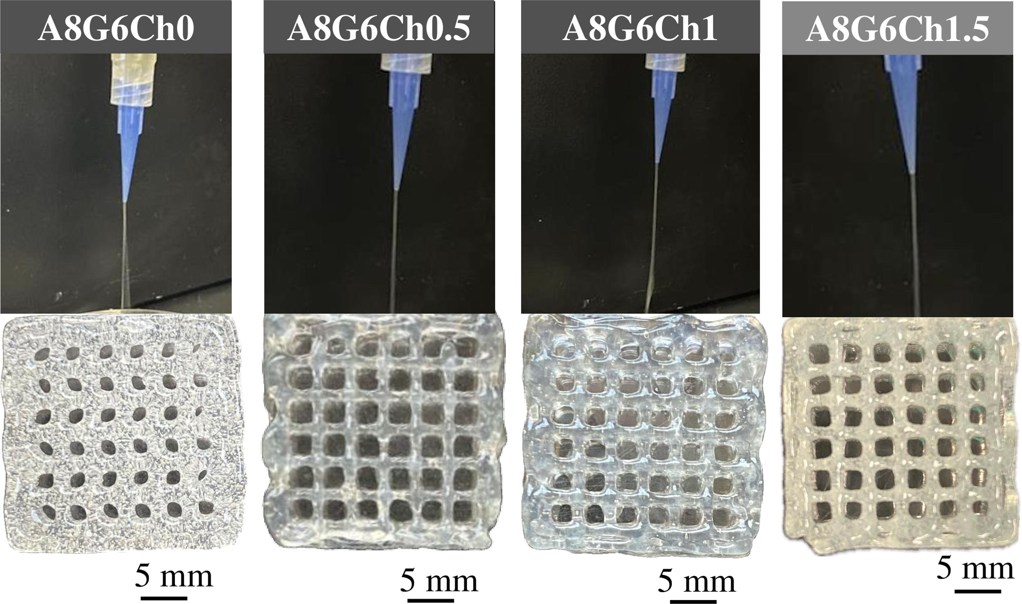
Representative images from manual dispensing of various bioink formulations.
In contrast, all other inks incorporated with chitosan formed coherent fibers, indicating that these inks are suitable for printing structures with good shape, structural fidelity, and high resolution. 37 The digital pictures illustrate the structures’ high print resolution, with clear pore outlines, well-defined structural borders, and continuous pores. We also explored different printing parameters to utilize these bioinks for printing the scaffolds with acceptable print resolution and structural fidelity during the minimum window required to apply the crosslinking agent. In the present study, sodium alginate precrosslinking further helped in forming continuous fibers when manually dispensed via the nozzle. Overall, preliminary analysis indicated that the sodium alginate–gelatin–chitosan bioinks were suitable for extrusion bioprinting.
Rheological properties of the inks
The molecular structure and formulation of polymer-based composites contribute to their viscoelastic behavior. To assess the correlation between molecular structure of the bioinks and viscoelastic behavior, rheological measurements must be performed in the LVR. The viscoelastic properties of inks were obtained through amplitude sweep and frequency sweep tests. Figure 4A displays representative amplitude sweeps (LVR) of four inks with varying concentrations of chitosan. Notably, both G′ and G′′ increased as chitosan content increased (p < 0.05). The inks used were elastic, with G′ > G′′, possibly due to the strong entangled network between the sodium alginate, gelatin, and chitosan biopolymers that offered elastic resistance. Representative frequency sweeps of the inks are shown in Fig. 4B. Notably, G′ was always significantly higher than G′′ (p < 0.05) for each ink type, and both increased linearly with increasing ω (p < 0.05). The inks exhibited elastic behavior similar to previous reports. 38,39

Rheological analysis of the inks.
The viscosity of the gel increased as the chitosan concentration increased from 0% to 1.5% (Fig. 4C). This increase in viscosity is likely due to a more robust network structure and higher resistance to flow. The viscosity was the highest at
Parameters m and n from a power–law model fit to the flow curves of various gels, prepared with increasing chitosan content
The model fitted the experimental data very well (p < 0.01 in each case), with all the model parameters also being significant (p < 0.01).
Figure 4D shows that the shear stress increased with increasing shear rate as well as chitosan concentration. The Herschel–Bulkley model
Bioprinting parameters
In extrusion-based 3D bioprinting, printing speed and pneumatic pressure critically affect print quality. Ink viscosity is critical to produce structural scaffolds with high fidelity. However, the accuracy and resolution of the printed scaffold are influenced by airflow pressure and speed. All these factors are essential for producing high-quality extrusion-based 3D bioprinted scaffolds. Our results showed that the ideal printing pressure and speed vary depending on the type of bioink utilized (Table 3). For scaffolds containing less than 1% w/v of chitosan, we observed that lower printing pressure and high speed were beneficial.
Observations of the bioprinted scaffold quality based on different printing parameters
The scaffolds’ quality (print resolution) was rated on a scale from 1 to 5—1 being the worst resolution and 5 being the highest resolution.
On the contrary, for A8G6Ch1.5 scaffolds, the best parameters include higher printing pressure (around 18 − 27 kPa) and lower printing speed (ranging 8 − 15 mm/s). The significance of printing pressure is particularly emphasized in extrusion bioprinting, where excessive pressures can introduce high shear forces, potentially compromising the integrity of the encapsulated cells. Therefore, fine-tuning the print (extrusion) pressure is recommended to ensure a smooth ink flow from the nozzle, facilitating the creation of intricate strands and ultimately resulting in high-resolution scaffolds without compromising cell viability. In addition, using narrow extrusion nozzles (250 μm Ø) and elevated extrusion pressure (60 kPa) proves that crafting scaffolds with specific orientations encourages muscle cells to align and form well-defined myotubes. 43
The resolution of scaffolds in extrusion-based 3D bioprinting depends on the printing speed. Studies have shown that 60 mm/s and 50 mm/s printing speeds improve resolution accuracy. 44,45 However, the choice of printing speed is influenced by the viscosity of the ink. 46 In this study, the printing pressure and speed for A8G6Ch0 were set lower due to the lower viscosity of inks with less than 1% w/v chitosan, making them easy to extrude. On the contrary, inks with the composition A8G6Ch1.5 have the highest viscosity and require more force for extrusion. Maintaining an optimal printing speed is essential to accurately deposit thin filaments around 1.5 mm in size. 47 This precision is necessary to achieve a high resolution in the scaffolds produced. Overall, the bioprinted composite scaffolds developed in this study retained their structure and flexibility, which are essential for guided skeletal muscle regeneration. 48
Quantitative assessment of bioprinted scaffolds
It is important to evaluate the quality of extrusion-based 3D bioprinted scaffolds by analyzing their outcomes using different inks. This can be done by quantitatively analyzing the printed parts and qualitatively assessing scaffold characteristics. The print accuracy test was executed to examine the resolution of the printed scaffolds across various chitosan concentrations (Fig. 5). Increasing chitosan concentration significantly impacted (p < 0.05) the quality of the printed scaffolds, resulting in improved resolution and print accuracy. Conversely, lower concentrations of chitosan used in scaffolds resulted in lower print accuracy and resolution. Although quantitative print accuracy assessments provide insights into the shape and structural accuracy, it is necessary to consider the qualitative aspects for a comprehensive analysis.
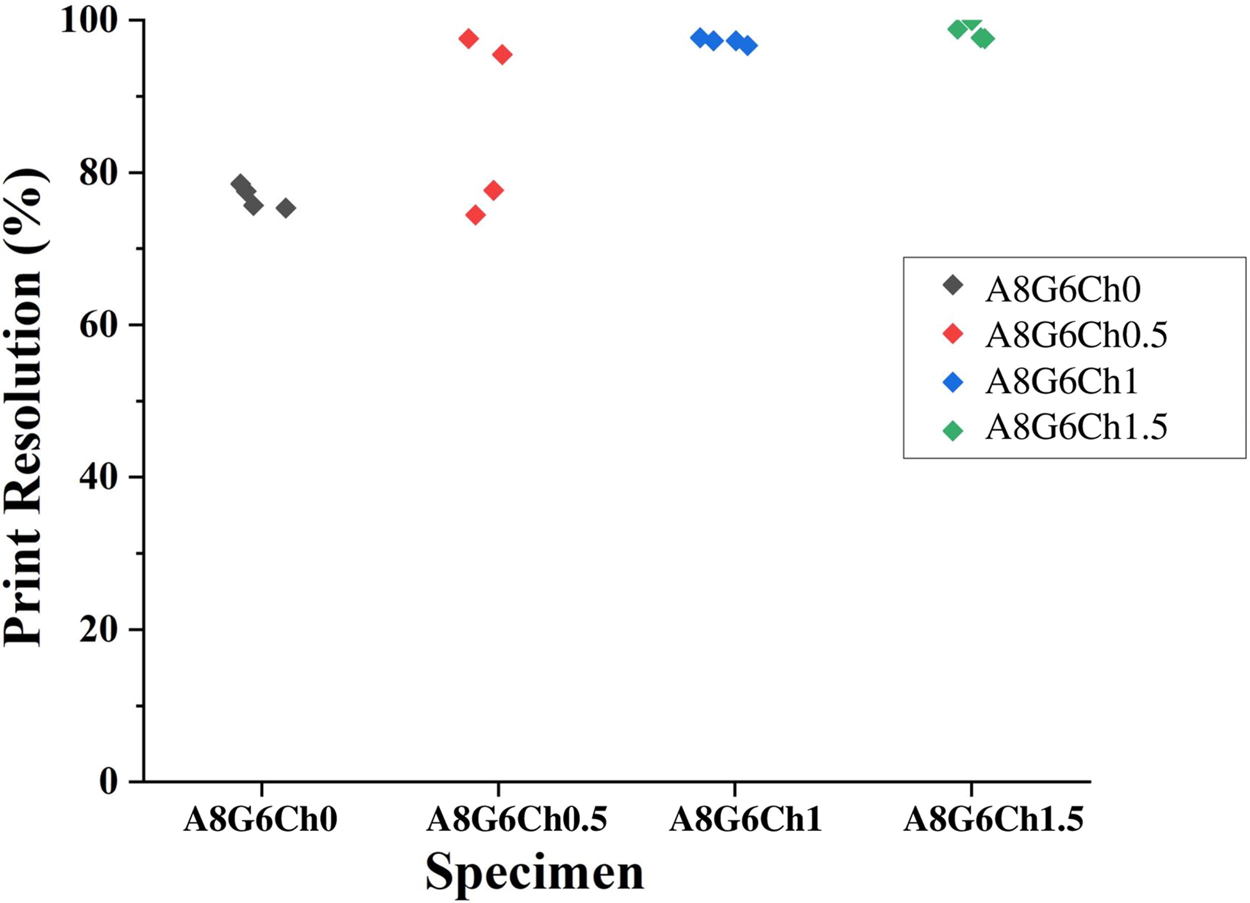
Print resolution of the various printed constructs.
Based on the manual dispensing and qualitative analysis, it was found that the use of A8G6Ch1.5 resulted in scaffolds with the highest print accuracy of 98%. These scaffolds maintained their shape and structural fidelity for at least 15 min or until the crosslinking solution was applied. The uniformity of the hydrogel structure is crucial for achieving an even distribution of cells within the scaffold. Scaffolds with superior structural fidelity exhibit uniform mechanical properties (stiffness) and controlled degradation kinetics, which is important for their practical applications. Sodium alginate-based inks have low viscosity, which makes printing scaffolds with exceptional structural fidelity challenging. However, this study successfully addressed this challenge by using 8% w/v sodium alginate, 6%w/v gelatin, and chitosan concentrations of 0.5%, 1%, and 1.5% w/v, respectively, resulting in scaffolds with superior print accuracy, resolution, and structural fidelity.
Mechanical properties of the scaffolds
The Young’s modulus of the scaffolds (Fig. 6), as measured using AFM, indicates that the sodium alginate–gelatin scaffolds with no chitosan had average EY around 42.76 ± 3.3 kPa. Expectedly, with increasing chitosan concentration, the average EY increased linearly and ranged between 42.76 kPa and 60 kPa. Previously, the tensile strength of such scaffolds has been reported to be in the range of 386 kPa to 693 kPa. 48 Others noted the stiffness of sodium alginate–chitosan–gelatin gels to be around 283 kPa to 383 kPa using AFM compression testing, 38 which is significantly higher than what we observed. However, the gels in that study were crosslinked using oxidized sodium alginate and carboxymethyl chitosan and fortified with polyethylene glycol, which contributed to the differences in EY . Feng et al. utilized shear wave ultrasound elastography to determine EY values representing the stiffness of the gastrocnemius muscle belly in healthy subjects. The mean EY value was 23.56 ± 4.08 kPa for the lateral gastrocnemius muscle. 49 The EY of the scaffolds we developed in the current study is notably higher than that reported for skeletal muscle in Feng et al. The variance in results could be partially attributed to the difference in techniques utilized to obtain the results. Nevertheless, while the scaffolds in this study have high EY values, they can still provide suitable mechanical support when utilized in skeletal muscle applications. The EY values may also differ depending on the location of the skeletal muscle, as well as the size of the load being applied to the muscle. Through ultrasonography, Isogai et al. found EY of the gluteus maximus to be 62.2 kPa under a 5N load. 50 This value falls within EY values reported in the current study. The stiffness of the scaffolds plays an essential role in providing a favorable biomechanical environment for cell infiltration from neighboring tissues and promoting skeletal muscle regeneration.
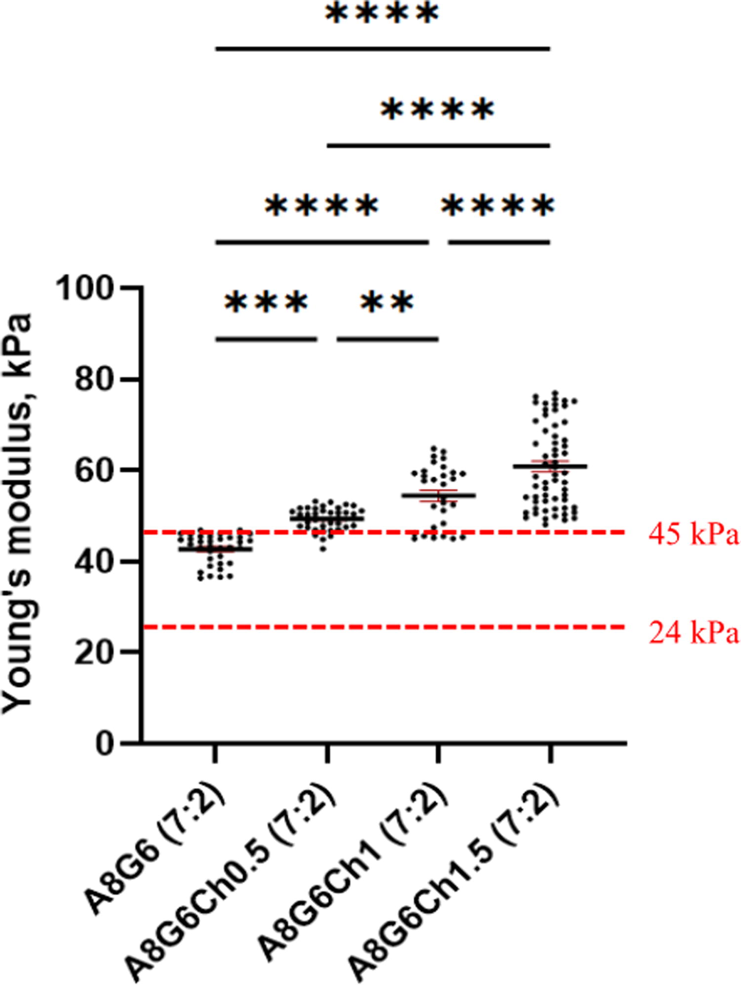
The Young’s modulus (EY ) of composite bioinks as measured using AFM and the red dotted line indicates the range of EY of healthy skeletal muscle. *Indicates p < 0.05 compared with A8G6Ch0. AFM, atomic force microscopy.
Swelling of the scaffolds
The swelling nature of the composite scaffolds is shown in Fig. 7A–C. For every composition, the scaffold weight increased significantly (p < 0.05) from initial to final weight (after 3, 7, 11, or 14 days). Specifically, the weights increased steadily for 11 days and decreased by day 14 due to sodium alginate and gelatin breakdown in the presence of DMEM. Although the samples containing the highest chitosan concentration (A8G6Ch1.5) exhibited the lowest weight before incubation, they exhibited the steepest weight increase (p = 0.0205) at day 3. The weights of these samples remained the highest compared with the other compositions for the preceding days. The A8G6Ch1 samples followed a similar trend, demonstrating a significant (p = 0.0135) increase in weight from day 0 to day 14 and continuously exhibited the second-highest weight at each time point. On day 0 and day 3, the A8G6Ch0 samples’ weights were higher than that of the A8G6Ch1 samples; however, the weights of the A8G6Ch0 were the lowest on day 7 and for the remainder of the incubation time frame. The A8G6Ch1.5 samples consistently showed the highest swelling percentage compared with all other samples. Interestingly, the swelling rate of all the scaffolds with chitosan increased for the first 11 days before decreasing.
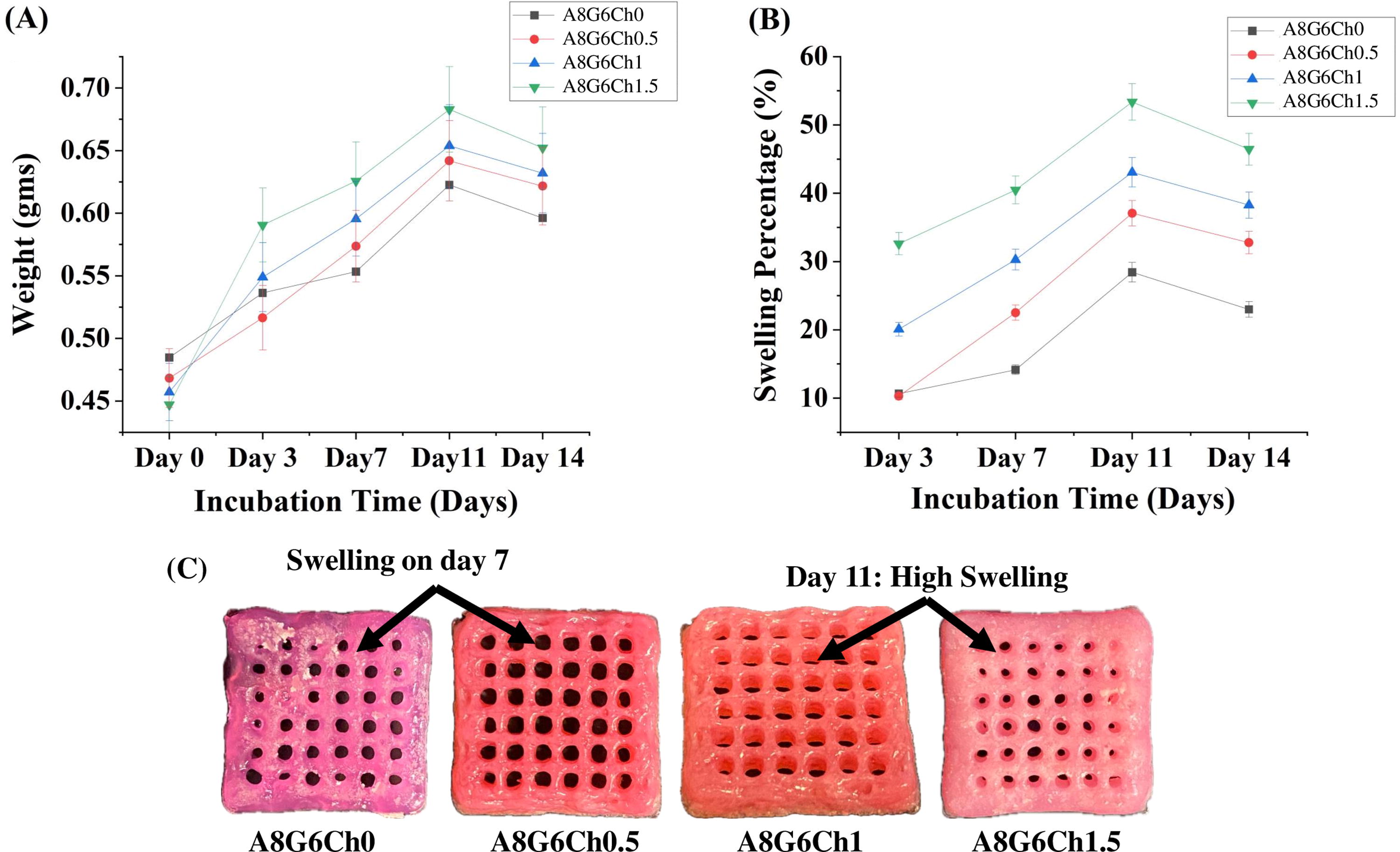
Moreover, increasing the chitosan concentration in the samples enhanced the swelling percentages. Except for day 3, the swelling percentage increased linearly with the chitosan concentration, indicating that higher concentrations of chitosan enhance the samples’ swelling capacity. This highlights the scaffold’s hydrophilic nature, essential for fluid absorption, nutrient diffusion, and tissue engineering applications. However, in a prior study, 46 a chitosan–gelatin–sodium alginate scaffold showed 1030% swelling within 60 min, which is quite higher than the current study. A sudden increase in swelling can be detrimental to the structural fidelity of the scaffolds.
Degradation of the scaffolds
The degradation behavior of scaffolds is shown in Fig. 8A–C. Each scaffold showed a significant weight loss (p < 0.05) over time, specifically experiencing a notable weight decline from day 0 to day 3. The weights of the samples, at all the time points tested, in decreasing order, were noted as follows: A8G6Ch1.5 > A8G6Ch1 > A8G6Ch0.5 > A8G6Ch0. On day 3, the sample containing no chitosan (A8G6Ch0) displayed the highest degradation, whereas the A8G6Ch0.5 sample had the lowest degradation. On day 7, the degradation of A8G6Ch0 and A8G6Ch1.5 remained unchanged, whereas A8G6Ch1 increased slightly, and A8G6Ch0.5 showed a significant increase (p < 0.05).
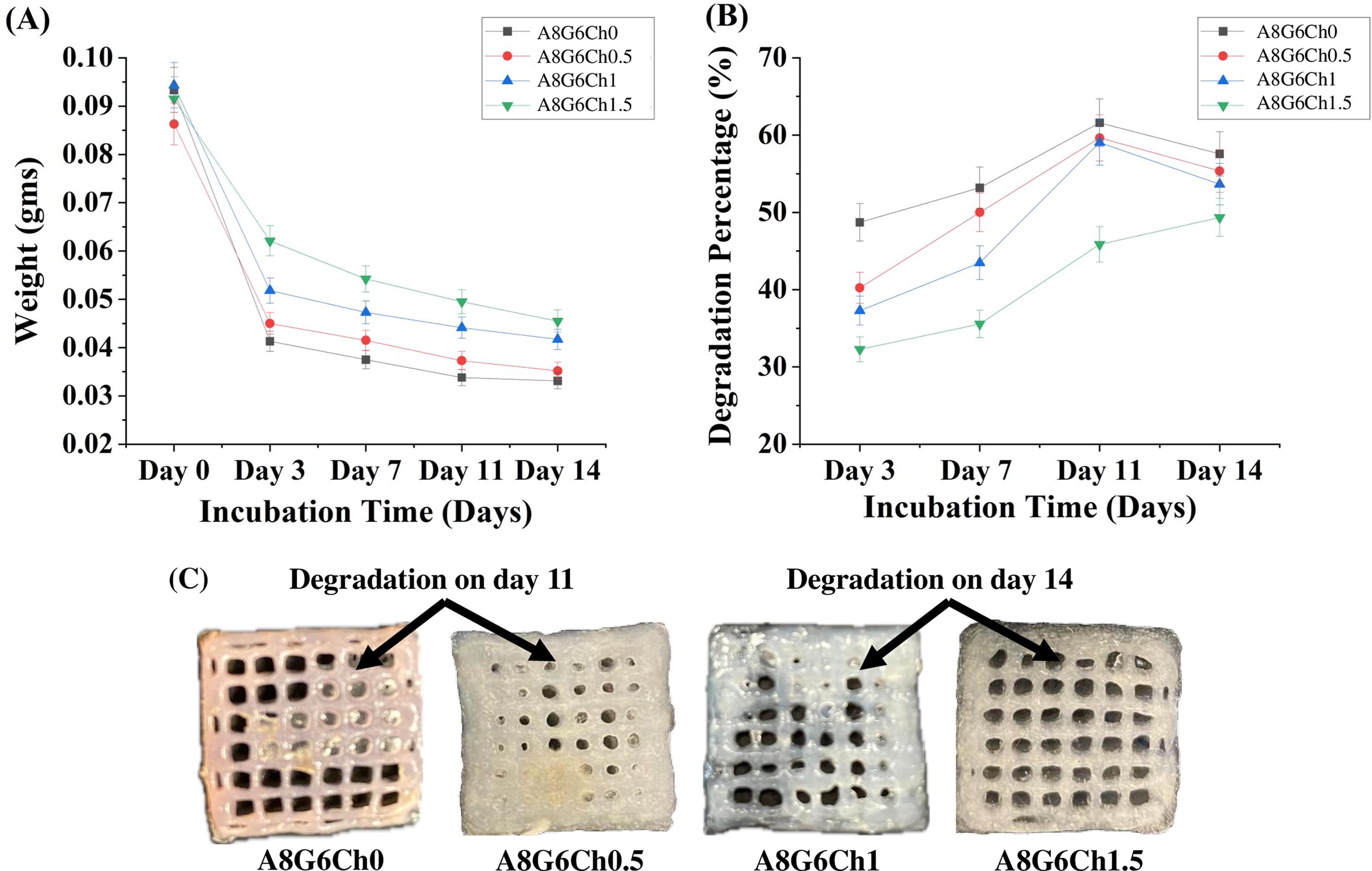
All samples degraded to 55–60% after day 11, except A8G6Ch1.5, which remained at 45%. By day 14, the degradation of the A8G6Ch0 sample decreased slightly, while the A8G6Ch0.5 and A8G6Ch1.5 samples’ degradation increased, and the A8G6Ch1 sample’s degradation remained the same. It is clear that the chitosan concentration influenced the scaffolds’ degradation rates. Specifically, A8G6Ch1.5 had the highest chitosan concentration and lowest degradation, making it useful for more extended stability in SMTE. Other studies have reported that the chitosan–gelatin–sodium alginate composite scaffolds demonstrate a degradation rate of ∼70% within 21 days. 39,51,52
The piezoelectric coefficient (d33) and voltage generated in the scaffolds
The effect of chitosan concentration on the piezoelectric coefficient of sodium alginate–gelatin–chitosan scaffolds was studied. The voltages produced by each sample were recorded before a load was applied and after various loads were applied. All replicate samples showed consistent patterns in voltage output. The voltage measured before the load was applied was the smallest output voltage for each sample. As the displacement was increased in increments of ∼2 mm, which consequently heightened the load on the samples, the resulting voltages also increased. The output voltage decreased significantly as the applied frequencies increased but remained within the same range (30 − 800 mV) for each sample. There were observable variations in the voltage changes between the chitosan concentrations at each displacement. Increasing the chitosan concentration from 0% to 0.5% corresponded to increased output voltage for each displacement, while further increasing the concentration to 1.5% decreased the voltage output, except for the fourth displacement. Despite some variation, the deviations were small. The applied frequencies and corresponding voltages for scaffold A8G6Ch0 are shown in Table 4. Figure 9A demonstrates that piezoelectric coefficients increase as the chitosan concentration increases from 0% to 1.5%, with the highest coefficient of 21.244 pC/N obtained at 1.5%.
Frequencies applied and corresponding voltages for the scaffold A8G6Ch0

The relationship between the chitosan concentration and the piezoelectric coefficient of a sample is not linear and can be influenced by the material’s properties at varying concentrations. Several studies have been conducted to investigate d 33 coefficient and potential applications of chitosan base composite. Prokhorov et al. 52 investigated the properties of chitosan-zinc oxide nanoparticle (CS-ZnO NP) films and found that the films had optimal properties at a weight percentage of 15% ZnO NPs, which included a piezoelectric coefficient (d 33) of 65.9 pC/N. These results highlight the potential for developing biocompatible sensors, actuators, and nanogenerators with specific performance metrics for flexible electronics and biomedical applications. In a recent study, Hänninen et al. 53 explored whether nanocellulose and chitosan could be a cheaper and renewable alternative to polyvinylidene fluoride (PVDF) films for sensors and energy harvesting. They found that films made of nanocellulose and chitosan exhibited piezoelectric responses ranging from 2 to 8 pC/N. Blending chitosan with nanocellulose could be a potential strategy to tailor the characteristics of eco-friendly piezoelectric films. Another study examining the piezoelectric properties of chitosan 54 revealed a d 33 coefficient of 18.4 pC/N at 330K under a 5-ton load, demonstrating chitosan’s potential as a piezoelectric element. 55
The piezoelectric properties of scaffolds can be activated through ultrasound. 56 We used ultrasound stimulation at an intensity of 1W/cm2 and a frequency of 1 MHz for 2 min every 24 h. As the ultrasound waves passed through the scaffold, they caused cyclic mechanical stresses that interacted with the piezoelectric material (chitosan), generating an EF. We measured the voltage (in mV) produced during ultrasound stimulation over a period of 14 days (Fig. 9B). We observed that a higher chitosan concentration (A8G6Ch1.5) generated a higher voltage, ranging from 6.5 to 7.3 mV. Also, the capacity for voltage generation remained consistent over the 14-day period. This indicates that increasing the concentration of piezoelectric chitosan enhances voltage generation within the scaffold, highlighting its potential for skeletal muscle tissue regeneration.
Cell viability and proliferation
The C2C12 myoblast cell line was utilized as a model for muscle cells to study how the scaffold affects cell viability and proliferation. Representative immunofluorescence labeled images (Fig. 10A) show cell attachment and growth on the scaffold surface with very few dead cells, indicating no toxicity. Quantitative analysis of live/dead assay data (Fig. 10B) revealed that the cell survival on every sample over a 2-day period is similar to that in the control cultures, that is, C2C12 cells cultured on a blank well without a scaffold. Our results agree with similar reports on the biocompatibility of sodium alginate-, gelatin-, and chitosan-based scaffolds. 57 –59 Moreover, significant increases in cell proliferation over a 7-day culture were noted in all the specimens (Fig. 10C). The results are expressed as fold change with respect to the culture on blank wells at a 2-day time point. Note that the cohort in Fig. 10C received no ultrasound. We observed that the cells cultured on A8G6Ch0 (no chitosan) proliferated 1.66-fold by day 4, whereas those cultured on scaffolds containing chitosan proliferated 2.9 to 3.4-fold (p < 0.01). This result indicates that the chitosan played an integral role in enhancing the biocompatibility and bioactivity of the scaffolds. However, no significant differences in cell proliferation were noted between the cultures for days 4 and 7.
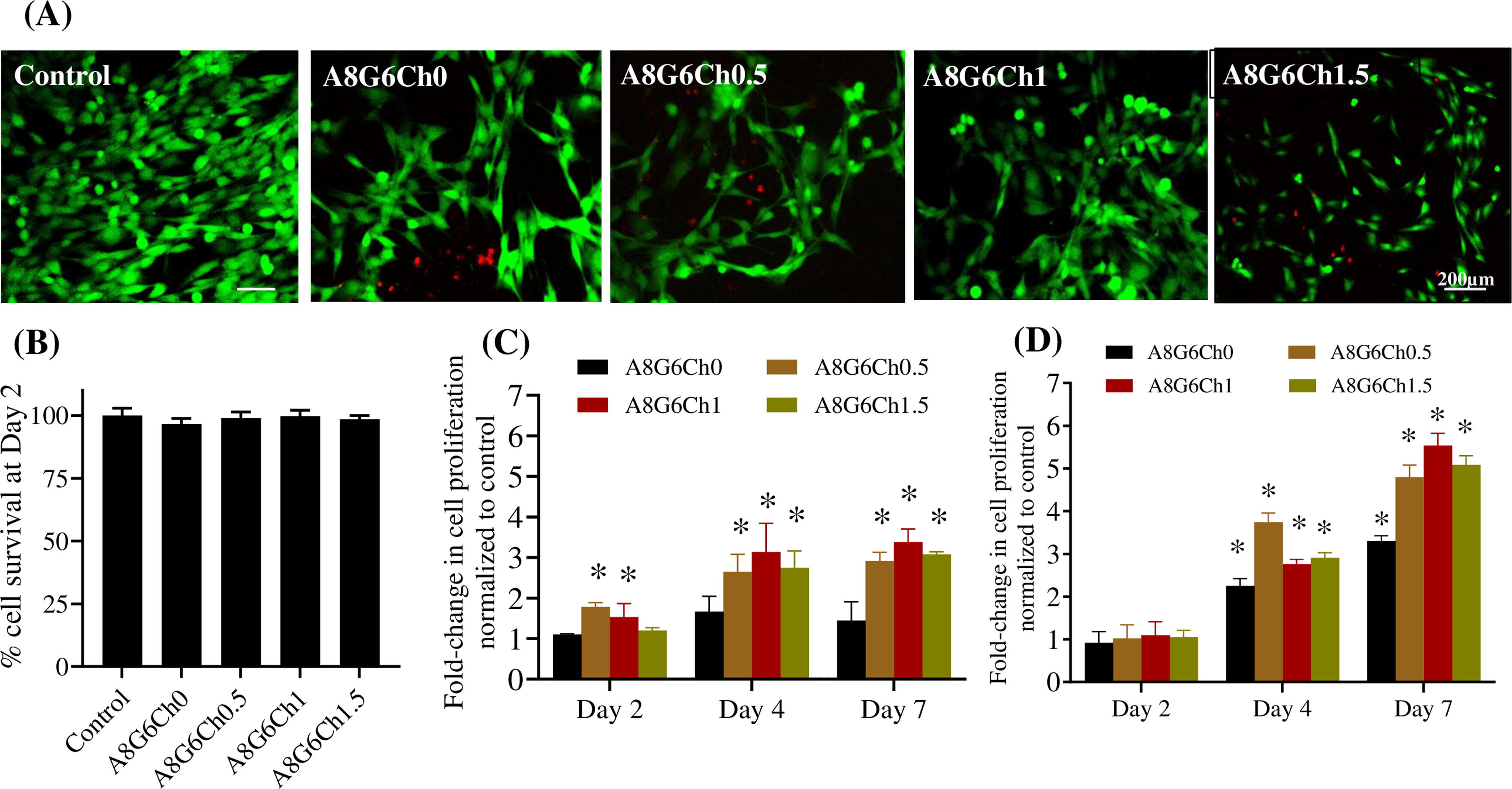
Importantly, in the presence of ultrasound (Fig. 10D), cells cultured on A8G6Ch0 scaffolds proliferated 2.23-fold by day 4 and 3.31-fold by day 7 (p < 0.05 vs. day 2 in both cases; p < 0.05 for day 4 vs. day 7). Similar to Fig. 10C, the results are expressed as fold change with respect to the cells cultured in blank wells at 2-day time points with ultrasound. For the chitosan-containing scaffolds, the cell proliferation increased in the range of 2.75–3.74-fold change by day 4 (p < 0.05) and in the range of 4.8–5.54-fold change by day 7 (p < 0.05) (Fig. 10D). Moreover, the fold change in the case of the chitosan-containing scaffolds on day 7 was significantly more than on day 4 (p < 0.05). This result indicates that with ultrasound application, the piezoelectric scaffolds containing chitosan have a prominent effect in promoting cell proliferation over time. We think the ultrasound stimulation results in molecular-level deformation in the chitosan-containing hydrogel scaffolds, activating their piezoelectricity, which upregulates cellular activities such as growth kinetics and proliferation over time. Of note, A8G6Ch1 exhibited the highest fold change at the end of day 7, indicating that the voltage generation in the range of 4.5–5.8 mV (Fig. 9B) is helpful for cell proliferation. In future studies, we will attune the voltage generation within this range to observe a more pronounced cell proliferation effect.
These observations are consistent with prior similar studies. Previously, we showed that the addition of piezoelectric material barium titanate (BaTiO3, BT) with polycaprolactone significantly enhanced the proliferation of preosteoblast MC3T3 mouse cells compared with controls without ultrasound stimulation. 24 In yet another study, adhesive piezoelectric antibacterial hydrogels containing carboxymethyl chitosan, tannic acid, carbomer, and FeWO4 nanorods enhanced reactive oxygen species generation, exhibited superior antibacterial efficiency, and accelerated full-thickness skin wound healing in bacteria-infected mice, when activated by ultrasound stimulation. 60 Our findings suggest that scaffolds containing higher amounts of chitosan significantly enhance cell proliferation, attachment, and viability, especially in the presence of ultrasound stimulation. This result is noteworthy as the piezoelectricity generated by the chitosan in the scaffolds helps promote muscle cell proliferation, thus offering promise in regenerating muscle after an injury
Footnotes
ACKNOWLEDGMENTS AND FUNDING SOURCES
The authors gratefully acknowledge the start-up funds from the
AUTHORS’ CONTRIBUTIONS
S.Y.S.: Investigation (lead); methodology (lead); software; data curation (lead); writing—original draft (supporting); and editing (supporting). S.B.: Investigation (lead); software; data curation (lead); writing—original draft (supporting); and editing (supporting). B.L.W.: Methodology (supporting); software; investigation (supporting); and data curation (supporting). E.G.E.: Methodology (supporting); software; investigation (supporting); and data curation (supporting). C.R.K.: Conceptualization (supporting); resources; validation; formal analysis; supervision (equal); and writing—review and editing (equal). H.R.: Conceptualization (supporting); resources; validation; formal analysis; and supervision (equal). K.G.: Formal analysis; review and editing (equal); and validation. P.S.: Conceptualization (lead); visualization; supervision; validation; writing—review and editing (equal); and project administration. All the authors mentioned in this article have reviewed and approved the final version submitted for publication. They have all agreed to be responsible for every aspect of the work and ensure its accuracy and integrity.
AUTHOR DISCLOSURE AND GHOSTWRITING
This article is an original work authored solely by the listed authors. No ghostwriters were involved in its preparation, and they take full responsibility for the content presented.
ABOUT THE AUTHORS
SUPPLEMENTARY MATERIAL
Supplementary Data S1
Abbreviations and Acronyms
References
Supplementary Material
Please find the following supplemental material available below.
For Open Access articles published under a Creative Commons License, all supplemental material carries the same license as the article it is associated with.
For non-Open Access articles published, all supplemental material carries a non-exclusive license, and permission requests for re-use of supplemental material or any part of supplemental material shall be sent directly to the copyright owner as specified in the copyright notice associated with the article.
