
Abstract
Abstract
Zebrafish, an established model organism in developmental biology, is also a valuable tool for imaging wound healing in space and time with cellular resolution. However, long-term imaging of wound healing poses technical challenges as wound healing occurs over multiple temporal scales. The traditional strategy of larval encapsulation in agarose successfully limits sample movement but impedes larval development and tissue regrowth and is therefore not amenable to long-term imaging of wound healing. To overcome this challenge, we engineered a functionally compartmentalized device, the zebrafish Wounding and Entrapment Device for Growth and Imaging (zWEDGI), to orient larvae for high-resolution microscopy, including confocal and second harmonic generation (SHG), while allowing unrestrained tail development and regrowth. In this device, larval viability was maintained and tail regrowth was improved over embedding in agarose. The quality of tail fiber SHG images collected from larvae in the device was similar to fixed samples but provided the benefit of time lapse data collection. Furthermore, we show that this device was amenable to long-term (>24 h) confocal microscopy of the caudal fin. Finally, the zWEDGI was designed and fabricated using readily available techniques so that it can be easily modified for diverse experimental imaging protocols.
Introduction
W
The regenerative capacity and functional innate immune system of zebrafish larvae make them ideally suited for examining both the early events in the wound response and the later events of healing and regrowth.7,10,11 Tail transection of the larval zebrafish provides an accessible regeneration model with a variety of genetic variants to mimic immune deficiencies 12 ; mutations and morpholino knockdown methodologies permit the assessment of various cellular components in the wound signaling, healing and regrowth response, 7 while fluorescently labeled proteins allow for imaging cellular responses. 13 However, to maximally utilize the genetic and optical advantages of the zebrafish to study the relationship between events occurring early in the wound response processes with later events important for healing and regrowth, devices that permit both the wounding and the healing to occur unhindered during the acquisition of high-resolution fluorescence images are required.
Light microscopy is an essential tool for capturing and analyzing changes occurring during wound healing. Although collecting cellular resolution images in an intact animal provides biologically relevant information that is virtually unobtainable in an in vitro setting, it comes with its own set of challenges, particularly due to the three-dimensional (3D) complexity of the tissues being imaged. Fortunately, a variety of microscopy techniques, such as confocal microscopy and multiphoton microscopy, permit optical sectioning and allow for high-resolution single sections to be reconstructed to reflect the entire 3D structure. The lower energy wavelengths utilized by multiphoton microscopy, which also provides optical sectioning capabilities, enables deeper optical sectioning and supports specimen viability.14,15
Furthermore, multiphoton microscopy can extract endogenous optical properties, such as second harmonic generation (SHG) to identify noncentrosymmetric biological structures, including collagen fibers, 16 or the fluorescence properties of metabolites, such as NADH. 17 Our recent studies using SHG to study the reorganization of fibers during wound healing in the zebrafish larval tail 4 illustrate the value of exploiting cellular contrast in this whole animal model. In addition, many of these endogenous contrast methods for noninvasive imaging, such as SHG, can be imaged in the live animal, and thus, the dynamics of the biological process of interest can be examined and manipulated. However, to fully take advantage of these exciting imaging opportunities, it is essential to develop experimental methods compatible with microscopy, thereby harnessing both the power of advanced imaging technology and the optical and genetic power of the zebrafish model.
Several methods are available for live imaging of zebrafish larvae. The common practice makes use of low-melting point (LMP) agarose for immobilizing the larvae in the correct orientation for microscopy. However, for the purpose of long-term imaging, the encapsulating agarose can impede growth and development. Other methods, such as placement of larvae in optically corrected tubing for rotational imaging, 10 microfluidics, 18 or wells (muwells; www.muwells.com/), allow for uninhibited growth but limit the options for the larval environment to be manipulated (i.e., wounding and chemical treatments). Although each of these solutions works for specific experimental and imaging procedure, we found that none was conducive for our application of high-resolution multiphoton imaging of the wound healing processes.
Therefore, we established a set of criteria for a device to meet our live imaging needs. The design of the device must (1) allow fabrication with readily available techniques and materials, (2) give consistent orientation of the larvae, (3) permit wounding within the device, (4) maintain larval viability over long periods with unrestrained wound healing and regrowth, and (5) provide high-resolution, 3D light microscopy data collection. The zebrafish Wounding and Entrapment Device for Growth and Imaging (zWEDGI) was developed to satisfy these design specifications, allowing the larvae to be loaded, wounded, and immediately imaged, thereby overcoming several of the limitations of current immobilization techniques. The zWEDGI device allows for the capture of high-resolution images over a range of imaging periods as the wound progresses through various stages of healing and regrowth. In this study, we detail the design used to satisfy the criteria listed above and validate how the device is an improvement over agarose embedding for tail transection wounding experiments. Furthermore, the functionally modular design of the zWEDGI device, along with the use of standard design and fabrication technologies, makes it readily modifiable as a restraining device that could be tailored for different development stages and a variety of experimental protocols.
Materials and Methods
Device design and fabrication
Device design was modeled using SolidWorks (Dassault Systems) to create a mold based on 3 days postfertilization (dpf) zebrafish larvae anatomic dimensions (Fig. 1). The molds for the device were 3D printed on a VIPERsi2 SLA System (3D Systems, Inc.) in Hi-Res mode, 0.075 mm beam diameter and 0.05 mm layer thickness, using Accura 60 photopolymer resin (3D Systems, Inc.). The molds were cleaned using a toothbrush, denatured alcohol, and compressed air to rid the mold of remaining uncured resin and postcured in a ProCure 350 UV Chamber (3D Systems, Inc.). To produce flush sealing surfaces, molds were sanded by rubbing the mold, geometry side down, across 320, 400, and 600 grit sand paper, progressively, on a surface plate that provided a very flat surface on which to place the sand paper.

Design and implementation of zWEDGI.
Sylgard 184 silicone elastomer polydimethylsiloxane (PDMS; Dow Corning Corp.) was mixed at a ratio of 5:1 to provide the increased cure-strength necessary for thin regions on the device. Approximately 0.75 mL of PDMS was poured into each mold cavity using a syringe and degassed in a vacuum desiccator for 45 min. A piece of 1″–3/4″ diameter × ¼″ thick borosilicate glass (McMaster-Carr Supply Company) was clamped on the PDMS-filled mold, expelling extra material. Molds were placed into a 100°C oven for 60 min to cure. Although a bar clamp can be used to hold the acrylic to the molds, to increase the number of molds that can be poured and cured at one time, we designed a five clamp mechanism.
After the molds were removed from the oven, the PDMS devices were removed from the molds with tweezers, beginning at the pull tab. The PDMS device was gently hand washed with denatured alcohol. The No. 1.5 glass bottom dish (60 mm dish, 30 mm glass well; In Vitro Scientific) and the zWEDGI PDMS device were placed into the PDC-001 Plasma Cleaner (Harrick Plasma). The PDMS was oriented upside-down, allowing the plasma electrons to modify the surface of the PDMS that will stick to the glass coverslip. The chamber was evacuated until pressure breached the threshold of 500 mTorr before the fine-tune valve was used to bleed room air into the chamber. The radio frequency generator was powered on to polarize the chamber gas to create the plasma. The zWEDGI PDMS and glass coverslip were exposed for ∼2 min after which the zWEDGI PDMS was flipped over to the correct orientation and placed on the center well of the glass bottom dish. The plasma bonding process sterilized the materials and formed a permanent bond between the PDMS device and glass coverslip.
Sample preparation
All protocols using zebrafish were approved by the University of Wisconsin-Madison Research Animals Resource Center. Adult zebrafish and embryos were maintained as described previously. 7 Strains used were wild type (AB), Tg(mpeg1:dendra2), 19 or Tg(-3.1ngn1:gfp-caax). 20 To prevent pigment formation, some larvae were maintained in E3 containing 0.2 mM N-phenylthiourea (Sigma-Aldrich). For wounding and imaging, larvae were anesthetized in E3 buffer containing 0.2 mg tricaine (ethyl 3-aminobenzoate; Sigma-Aldrich). 21 To minimize adherence of larvae to the glass coverslip, channels were filled with 1% skim milk for 10 min, gently submerged several times in reverse osmosis (RO) water to rinse, and air-dried before use.
A single larva was loaded into the loading chamber with a large orifice pipette tip (Fisherbrand) and manipulated with a gel loading pipette tip or a whisker tool such that the dorsal side faced the straighter edge of the loading chamber with the tail oriented toward the restraining tunnel. Fluid was withdrawn from the wounding chamber, causing the larva to flow into the restraining tunnel, ultimately removing the majority of the liquid while maintaining moisture around the larva. LMP agarose (1%) (Sigma-Aldrich) in tricaine/E3 (∼38°C) was placed over the larva's head, filling the loading chamber and then allowed to solidify with the larva in the proper position. Additional tricaine/E3 was added to the wounding chamber as needed. This process was repeated for the remaining two device channels. Additional tricaine/E3 was added either over the agarose (for wounding or short-term imaging) or filling the culture dish (for long-term imaging). Larvae can be imaged at this point (unwounded) or wounded. Wounding was performed as previously described, 21 using a sterile scalpel blade to transect the tail fin posterior to the notochord, in the wounding chamber (Supplementary Movie S1; Supplementary Data are available online at www.liebertpub.com/zeb). Following wounding, additional tricaine/E3 can be added. The culture dish lid was replaced to minimize evaporation.
Stereo microscopy
To assess for growth and viability, larvae were imaged using an Olympus SZ40 dissecting microscope, zoom 3 or 3.5. Videos (20 s) were captured using an OptixCam Summit Series color camera and TSView 7 (ver 7.3.1.7; Xintu Photonics) software.
Confocal microscopy
Immunofluorescence images were acquired with a confocal microscope (FluoView FV1000; Olympus) using an NA 0.75/20 × objective. Z series were acquired using 180 μm pinhole and 5 μm step size with z-stacks collected every 15 min. Maximum intensity projections of the z-stacks for each time point were generated using FIJI software (http://fiji.sc/Fiji). 22 Each maximum intensity projection was then connected into a time series. To account for growth and movement of the fin, multiple time series were collected to create a single movie. Each individual time series was registered, using the FIJI StackReg plugin, 23 to stabilize the image for drift and growth before combining time series with Quicktime Pro (Apple) into a single continuous movie.
SHG multiphoton microscopy
Tails were imaged at the Laboratory for Optical and Computational Instrumentation on a custom-built multiphoton microscope. 24 Briefly, the microscope consists of a tunable titanium sapphire laser (Mira–Coherent, Inc.) with a Nikon inverted microscope (TE2000; Nikon) driven by open source software (http://loci.wisc.edu/software/wiscscan). A 40 × water immersion lens (1.25 NA; Nikon) was used with the laser tuned to 890 nm. Backward SHG was collected through a 445/20 emission filter (Semrock) and detected on a H7422 Photomultiplier Tube (PMT; Hamamatsu). Images were collected as z-stacks with optical sections 3 μm apart, at 512 × 512 resolution, at the wound site every 4 min for more than 2 h. Transmission images (Bio-Rad) were simultaneously collected. Images were processed as sum z-projection using FIJI.
Viability and wound regrowth assessment
Wild-type larvae (2 dpf) were divided into three treatment conditions: unrestrained (“E3/tricaine”)—wounded and maintained in tricaine/E3 (in 35 mm dish, five larvae in 2 mL tricaine/E3); fully restrained (“1% agar”)—wounded in tricaine/E3, then mounted in a pad of 1% LMP agarose, and covered with tricaine/E3 (glass-bottomed 60 mm dish, three larvae per dish); partially restrained (“zWEDGI”)—loaded into zWEDGI and wounded as described above (glass-bottomed 60 mm dish, three larvae per dish). Videos (20 s) were collected on 0 days post-wound (within 30 min of wounding), 1 and 2 dpw using TSView7 software (Tucsen Photonics) controlling an OptixCam Summit Series camera (Tucsen Photonics) mounted on a dissecting microscope (Olympus CZ-CTV).
Presence of heartbeat was also noted at time of video collection. Regenerate length (length of tail from end of notochord to wound edge) and body length (length of straight line from center of eye to end of tail) were measured from the videos using FIJI. Data were collected from three independent replicates, each with 9–12 larvae per treatment. Statistical analyses for body and regenerate length were performed in R (www.r-project.org) comparing between experimental conditions using analysis of variance with Tukey method for multiple comparisons. 25 Graphs and survival analysis (log-rank test) were performed using Prism 6 software (GraphPad). For all tests, p-value <0.05 was considered statistically significant.
Dye diffusion
Fixed 3 dpf larvae were loaded into zWEDGI channel, with 1% LMP agarose in loading chamber. Rhodamine 6G (1 mg/mL; Sigma-Aldrich) was used to fill wounding chamber. Imaged z-stacks, 20 μm intervals of multiple regions of interest to collect full length of the larvae, were collected every 10–15 min for 2 h using a multiphoton microscope, with a 10 × 0.5 NA lens (Nikon, Mehlville NY) and 830 nm laser excitation and a 580 LP filter (Chroma, Burlington, VT) for emission.
Results
Final design geometries and device fabrication
The final design and specific geometries of the zWEDGI presented here resulted from initial conceptual design considerations followed by iterative testing using fixed larvae to assess loading, orienting, and wounding. The basic channel design consisted of four functional areas—a rectangular loading chamber, a wedge-shaped funnel for x and y orientation of the larva, a wedge-shaped restraining tunnel for further z-axis orientation, and a semicircular wounding chamber. A single device consisted of three channels (Fig. 1A).
Because we wanted this device to be readily accessible to the community, we established our first criterion, namely that we utilize a straightforward workflow consisting of standard, available techniques that can be readily modified for experiment-specific needs. The SolidWorks design (Fig. 1B; available at https://morgridge.org/designs/) was used to generate a 3D printed mold that was then filled with liquid PDMS (Fig. 1C). To generate the open chambers, a piece of acrylic was clamped on the mold, making direct contact with the top of the loading and wounding chamber portions of the mold, forcing out excess PDMS. Following curing, the PDMS was carefully removed from the mold and plasma bonded to the glass of a 60 mm imaging dish, creating the final device (Fig. 1D). The final device design and manufacturing were subjected to assessments for viability and imaging, as described below.
Loading and wounding larvae in the zWEDGI device
The second criterion for our design was to permit the consistent orientation of the larva such that the larva lies on its side with tail as flat as possible against the cover glass, with sufficient space in the loading chamber to permit manipulation of the larva into the proper location. Zebrafish larvae were loaded into the zWEDGI channel (Fig. 2A) such that the tail was oriented toward the restraining tunnel and the dorsal side of the fish was toward the flatter edge of the wedge while the yolk is nestled into the angled portion of the wedge. The loading chamber is open, rectangular, and larger than the larvae, allowing the larva to be rotated and oriented in the loading chamber as needed so that the larger yolk sac will “wedge” the larva into place at the narrow restraining tunnel. Furthermore, the thickness of the PDMS did not exceed 1 mm in thickness, which would have impeded manipulation of the larva. Serendipitously, the volume ratios of the wounding and loading chambers exhibited fluidic mechanics allowing the larva to be easily drawn into the restraining tunnel, facilitated by the funnel structure of the loading chamber.
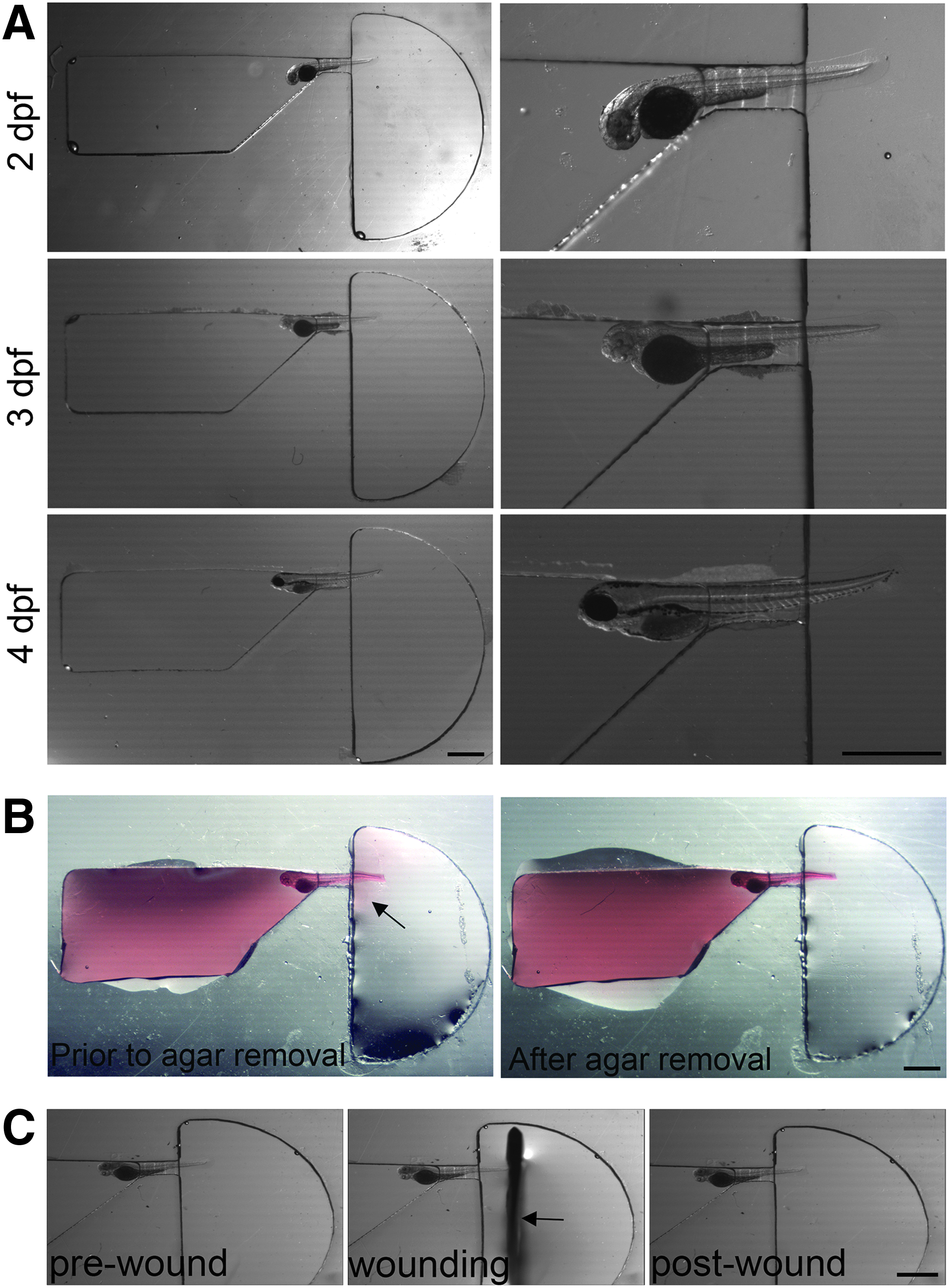
Positioning of larva in channel.
The wedge shape of the loading chamber leading into the restraining tunnel can accommodate a variety of the early larval stages, from 2 to 4 dpf. In addition, the easily modifiable SolidWorks design permits the size and angle of the wedge to be adjusted to accommodate different sizes and shapes of larvae for additional experimental applications. The tunnel width (450 μm) was dimensioned just large enough for the tail to enter undamaged yet small enough to inhibit the yolk sac from entering the tunnel, effectively wedging the larva in place. In addition, the wedge nature of the tunnel itself (entry height of 500 μm, exit of 300 μm; Fig. 1B) further assisted the orientation the tail in the z-axis. To prevent movement of the larva once properly positioned in the channel, most of the buffer was removed from the loading chamber and replaced with 1% LMP agarose (Fig. 2B). A small amount of agarose travels through the restraining tunnel into the wounding chamber, but this was easily removed, leaving the tail unrestrained and suspended in buffer in the wounding chamber.
Because our interest is in imaging a variety of wound healing and regrowth processes in the zebrafish caudal fin transection model, this ability to isolate the restraining agarose in the loading chamber from buffer only in the wounding chamber, thereby leaving the tail free, contributes to satisfying our third requirement, namely that the larval tail should be exposed in a manner that permits both ease of wounding and subsequent imaging. However, in addition to having the tail unrestrained by agarose, the wounding chamber had to be designed to permit the use of a scalpel blade for tail transection. This required a chamber with a long axis parallel to the orientation of the wound to accommodate the blade, while the chamber axis perpendicular to the wound did not need to be wide, and a half circle satisfied this requirement. Having the half circle off center with respect to the restraining tunnel accommodated the motion of the blade across the tail (Fig. 2C and Supplementary Movie S1).
Assessment of viability and postwound regrowth
Wound healing and tissue regrowth occur over a range of time scales, on the order of minutes, hours, and days. Thus, it was important that the zWEDGI has not only the capability for wounding and imaging in the same device, to accommodate the imaging of pre- and immediately postwound events, but also to support viability and regrowth over multiple days. This meant that the device must accommodate a reasonable volume of buffer for larval survival, and materials used in device manufacture must be nontoxic in aqueous environments.
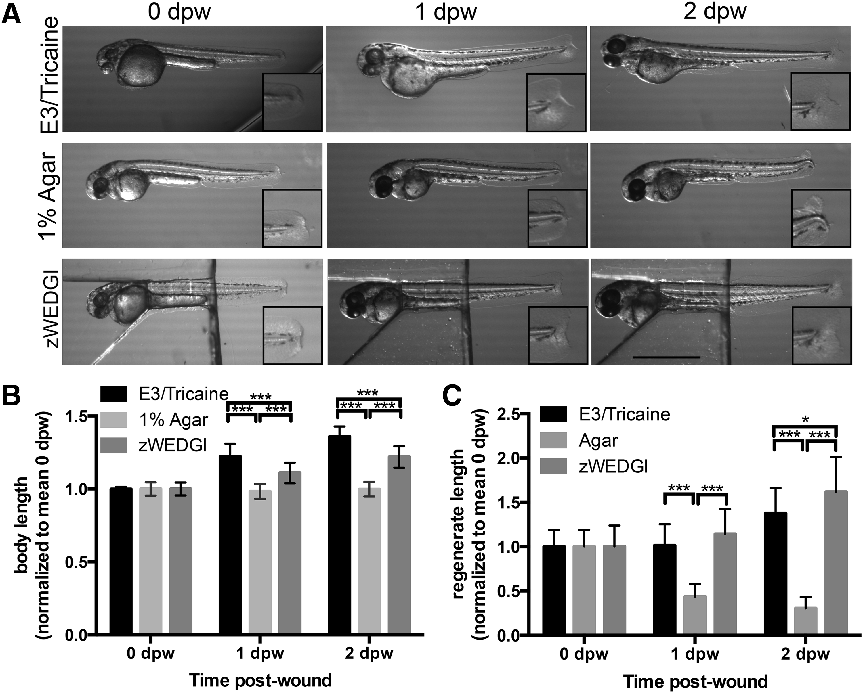
To address our fourth criterion, namely that specimen viability must be maintained over long periods of time, on the order of hours and even days, and permit unrestrained wound healing and regrowth, we conducted an experiment to assess both survival and caudal fin wound regrowth. To assess survival, we noted the presence or absence of a heart beat in anesthetized, wounded larvae either unrestrained in E3/tricaine, mounted in standard 1% LMP agarose or mounted in zWEDGI channels. The presence of the heartbeat was noted within 30 min of the wound (0 dpw), at 1 and at 2 dpw. Larvae in all treatments showed high survival rates (100% in all treatments on 0 and 1 dpw), with only minor reductions in survival in agarose and zWEDGI treatments compared to unrestrained control larva at 2 dpw (E3/tricaine = 100%, n = 30 larvae; agarose = 86.7%, n = 30 larvae; zWEDGI = 96.4%, n = 28 larvae; p = 0.0643), indicating that neither material used, the design restraint nor the partial agarose restraint used in the zWEDGI impacted viability.
In addition to survival, the sample must be able to grow and develop within the restraining device. To assess body growth, we compared the normalized body length (from middle of eye to tip of notochord) of unrestrained larvae in buffer to those in agarose or the zWEDGI (Fig. 3A). The body length of unrestrained larvae increased significantly compared to those in agarose (p < 0.001) or the zWEDGI (p < 0.001), although the body length of those larvae in the zWEDGI more closely approximated that of the unrestrained larvae (Fig. 3B). These data suggest that the unrestrained caudal region in the zWEDGI permits growth more similar to the unrestrained condition than complete agarose enclosure, although the agarose maintaining the head position may impede overall body growth.
Growth and caudal fin regrowth are maintained in the zWEDGI.
For our studies, it is essential that the wound be able to heal and regrow unimpaired. We found that complete agarose encapsulation dramatically inhibited caudal fin regrowth following wounding (Fig. 3A). To assess the effect of mounting conditions on tail regrowth following wounding, we measured the length of the tail fin from the end of the notochord to the edge of the fin (regenerate length) (Fig. 3C). Because the exact location of the tail fin transection can vary, the measurements were normalized to the mean value of the regenerate length shortly after wounding (0 dpw). The regenerate length of larvae embedded in agarose was much smaller than that of either the zWEDGI (p < 0.0001) or buffer (p < 0.0001) at 1 or 2 dpw, while the regenerate length was not different between larvae in the zWEDGI and buffer (p = 0.072) at 1 dpw but was slightly greater in the zWEDGI than the buffer at 2 dpw (p = 0.0043). While the regenerate length increased over time in both unrestrained and zWEDGI treatment, the regenerate length of the larvae in agarose actually decreased over time. This appeared to result from the continued growth of the notochord, while the fin regrowth was inhibited by the agarose (Fig. 3A), resulting in some bent notochord tips at later time points. These results indicate that wound healing cannot progress when the larva is embedded in agarose, whereas the absence of agarose around the tail in the zWEDGI allowed postwound regrowth similar to the completely unrestrained condition, providing a substantial improvement over the standard agarose embedding method for wound healing studies.
Light microscopy of larval tails in the zWEDGI device
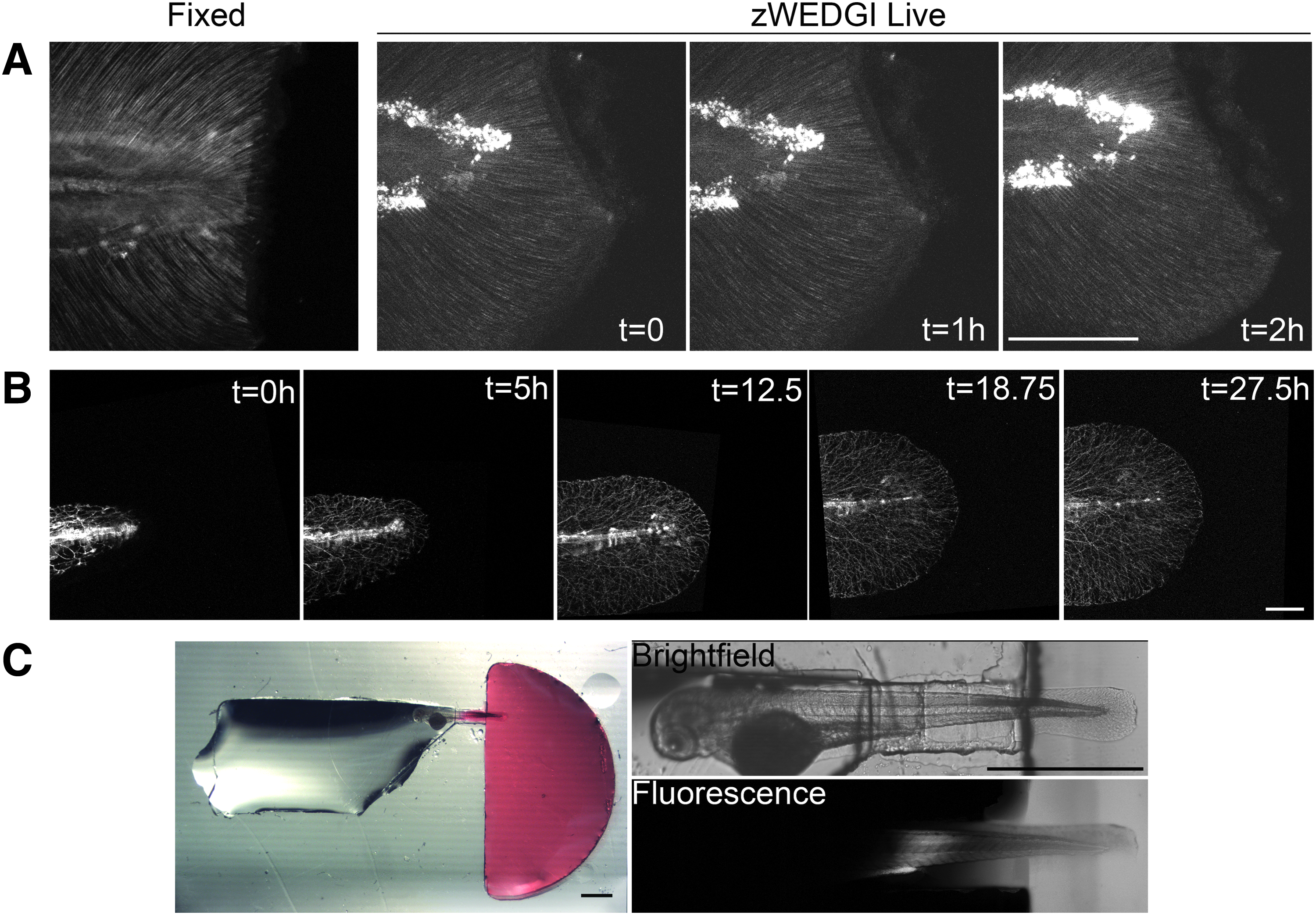
To assess the capability of collecting high-resolution images of larval tails in the zWEDGI, we collected SHG images of wounded tails using microscope imaging parameters similar to those utilized for our previous work imaging fixed tails.4,21 SHG microscopy can be used to detect certain organized molecules, including some collagens. 16 Using SHG in the larval tail, we detect fibers extending out through the caudal fin that are likely to be collagen-rich actinotrichia.26,27 These fibers appear to be important for proper wound healing, 4 thus live imaging using SHG will likely provide valuable insight into their role during caudal fin regrowth.
We found that images collected with the zWEDGI provided quality comparable to those obtained with fixed samples (Fig. 4A and Supplementary Movie S2). Furthermore, with the zWEDGI, because the wounding can occur within the device, data can be collected both before the wounding and immediately following wounding, which cannot be done as quickly when the wounding has to occur before agarose embedding. This image sequence shows the wound contraction and relaxation that occur following tail transection.
High-resolution light microscopy of larval tails in zWEDGI.
The live SHG imaging illustrates the utility of the zWEDGI for rapidly imaging events immediately following wounding. However, we are also interested in wound healing and regrowth processes that occur over a range of time scales, and thus, it was important to establish that the zWEDGI could be used over a longer time window, more than 24 h. To demonstrate such long-term imaging, as well as the versatility of the zWEDGI for different imaging modalities, we collected confocal microscopy data of peripheral axon branching in the developing larva expressing green fluorescent protein (GFP)-labeled primary sensory neurons driven under the neurogenin1 promoter [Tg(-3.1ngn:gfp-caax)]. For more than 24 h, z-stacks of the caudal fin were collected every 15 min (Fig. 4B and Supplementary Movie S3). Although the x, y location had to be adjusted during data collection to compensate for tail growth, larval viability and image quality were maintained. Thus, the zWEDGI can be used for imaging both early and late wound healing events using different optical microscopy modalities, providing important versatility for wound healing investigations.
Semi-isolation of head and tail region
Although not one of our device design criteria, we found that the zWEDGI generated a situation where the head, in agarose, and tail, free in buffer, experience environments with different diffusion properties. We further investigated the extent of this differential by adding rhodamine 6G to the wounding chamber after the 1% agarose in the head region had solidified. We chose rhodamine 6G as a fluorescent molecule of similar molecular weight (MW = 479.01) to small molecules of interest to our wound healing studies, namely ATP (MW = 507.18) or fMLP (MW = 437.55). We found that over a 2-h time frame, diffusion of the rhodamine 6G was essentially confined to the wounding chamber and the restraining tunnel (Fig. 4C), leaving the head unexposed to the compound. At least for limited time windows, our device could be used for localized applications of drugs or infectious agents to the wound area to study how they affect regeneration, thereby enabling novel applications to the study of wound healing.
Discussion
The zWEDGI design presented here has met, and even exceeded, our functional design specifications. In terms of our established criteria, the larval survival was similar to that of unrestrained larvae, confirming that PDMS does not adversely affect zebrafish larvae and that the mechanical restraint of the device supports larval survival. With respect to wound healing criteria, the device excels in comparison to other imaging methods as it allows the caudal fin to be transected within the device and immediately imaged. More importantly, we demonstrated that caudal fin regrowth in the zWEDGI approximated that of unrestrained larvae in comparison to agarose embedding, in which larvae wound regeneration was dramatically inhibited.
Agarose embedding in which a region of agarose around the tail can be removed following solidification can relieve the inhibition of the tail regrowth but requires that the user rapidly line up and orient all of the larvae before the gelling of the agarose. The zWEDGI not only provides consistency to the x, y location (because the channels are in fixed locations) but the wedge-shaped design of the restraining tunnel assists in orienting the caudal fin parallel to the imaging surface. Furthermore, unlike the agarose embedding method, the orientation of larvae in the zWEDGI can be adjusted individually, while they are in buffer rather than in agarose, negating the requirement for rapid manipulation at this step. The zWEDGI met our imaging requirements as it orients the larvae within the 1 mm working distance limitation of the lenses we are using and yields images with quality similar to that of fixed samples.
In addition to these established criteria, the zWEDGI exhibited added benefits applicable to a variety of imaging experiments and methods. First, the larvae seem to create a temporary isolation between the loading chamber and the wounding chamber as it plugs the tunnel (Fig. 2B). This created a semi-isolation situation where the diffusion characteristics of the head region are different from the tail, limiting the diffusion of small aqueous molecules from the wound region to the head, at least over a 2-h time window. This characteristic may be useful for drug or treatment testing scenarios during which the user may want to expose only the wound region to a substituent such as inhibitors, infective agents, 28 hormones, 29 or growth factors. 30
Furthermore, the fact that the channels isolate the larvae from one another provides benefits, based on the ability to keep track of specimens across time points. Handling larvae embedded in agarose within a glass bottom dish is difficult and makes maintaining individual larval identity challenging. In contrast, the isolating nature of the zWEDGI structure allows for easy identification of the individual larvae after long periods of growth or imaging. Thus, larvae of different genotypes or with different pretreatments can be loaded into different channels but imaged within the same dish, improving consistency of imaging and handling across experimental conditions. Also, the ability to keep track of respective larvae would allow for postimaging assessments (e.g., genotyping, subsequent antibody labeling). Finally, the ability to isolate each larva within its own channel provides the potential for manipulating an individual larva's environment.
The standard manufacturing techniques and modular design of the zWEDGI make it easily amenable to modification. Perhaps the most valuable aspect of the zWEDGI is the potential for geometric changes to suit other uses. For example, the geometries of the various functional regions of the channel can be modified to accommodate later developmental stages or imaging studies of other regions of the larvae. For example, geometric modifications of the restraining tunnel could accommodate a wider spectrum of developmental stages as well as other orientations of the larvae with respect to the microscope lens. Such orientation changes could allow for dorsal or ventral perspectives for imaging other regions such as the brain, heart, or liver. We are particularly interested in reducing the size of the wounding chamber to allow space for more channels on one dish, permitting more specimens to be imaged in a single experiment.
The applicability of this device to a variety of experimental protocols is further strengthened due to the increasing access to 3D printing. Not only has the price of 3D printers reduced significantly in the past 3 years but also the software has greatly improved, and the array of materials used for printing is increasing. 31 Although our devices are printed with expensive and high-resolution machinery, it soon may be possible to print these molds on less expensive printers using a variety of materials. Therefore, if biocompatible 3D printing materials are established, it may be possible to 3D print the actual zWEDGI device directly, in place of pouring the PDMS.
The zWEDGI provides an accessible solution for wounding and immobilizing zebrafish larvae for the purpose of high-resolution live imaging. It was created using standard, readily available materials and methodologies, aids in proper larval orientation, permits wounding, maintains larval viability, allows the collection of high-resolution images over rapid or long-term time windows, and allows for environmental manipulation and identification of individual larva. The intension of this work was not necessarily to generate a stand-alone product but rather to provide a new modular design and accessible concept for larval restraint for live imaging. Therefore, in the spirit of this open access, the SolidWorks design for the current zWEDGI is available for direct download at https://morgridge.org/designs/. The modular geometries of the zWEDGI design, along with growing access and in reduction in cost of 3D printing, allows the fabrication of experiment-specific zWEDGI varients. These characteristics make the zWEDGI a powerful tool for live imaging of wound healing processes.
Footnotes
Acknowledgments
We thank the members of the Huttenlocher lab and the Morgridge Medical Engineering group for useful input on this project. We thank Dr. Mary Halloran for providing the tg-ngn:gfp-caax zebrafish line. We also thank Guille Minitti for assistance with image measurements. This work was supported by the Morgridge Institute for Research Medical Engineering Group, the Laboratory for Optical and Computational Instrumentation (LOCI), and the NIH grant R01GM102924.
Disclosure Statement
No competing financial interests exist.
References
Supplementary Material
Please find the following supplemental material available below.
For Open Access articles published under a Creative Commons License, all supplemental material carries the same license as the article it is associated with.
For non-Open Access articles published, all supplemental material carries a non-exclusive license, and permission requests for re-use of supplemental material or any part of supplemental material shall be sent directly to the copyright owner as specified in the copyright notice associated with the article.