
Abstract
Instrument localization is widely used in computer-assisted surgery. Most existing navigation systems monitor the position of the surgical instrument’s stylus-tip in non-visible surgical areas. However, a gap still exists in meeting the surgeons’ requirements for instrument monitoring. It is difficult for them to monitor the instrument’s working direction and its contact with the lesion area without an intuitive silhouette or additional feature points on the instrument. This paper introduces a full-tool surgical navigation for enhancing instrument localization and visualization in surgery, providing silhouette monitoring and directional indications. The key to overcoming these challenges lies in reconstructing the surgical instrument, as well as calibrating the stylus-tip and direction of the key part on the instrument. Our method achieves this through a silhouette carving reconstruction method with a feature-dense position-sensing marker. In the experiment, the fiducial registration error of our method reaches 0.496 mm, and the relative orientation error is 1.401°. These localization and orientation accuracies demonstrate the potential of full-tool navigation system in surgeries.
Keywords
Introduction
Surgical navigation is a key component of the computer-assisted surgery (CAS), and can be categorized into electromagnetic navigation (Figure 1(a)),1,2 optical navigation (Figure 1(b)),3,4 and visual navigation (Figure 1(c) and (d)).5–7 Enhancing accuracy, robustness, and visibility of surgical localization facilitates surgeons, especially inexperienced ones, in performing highly precise surgery. It can reduce the error and risk of surgery, and improve the efficiency of operation and therapeutic effect.
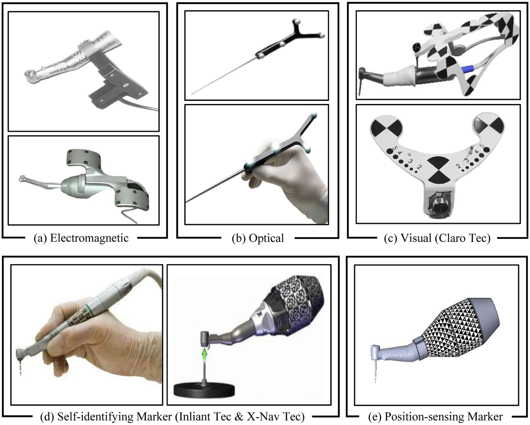
Computer-aided technologies in surgical navigation: (a) electromagnetic navigation, (b) optical navigation, (c) visual navigation using feature array patterns (Claro Technology), (d) visual navigation using self-identifying markers (Inliant Technology and X-Nav Technology), and (e) visual navigation using position-sensing markers (HydraMarker).
Most existing navigation systems provide surgeons with precise localization of the surgical instrument’s stylus-tip in non-visible surgical areas.8–10 Surgeons can monitor the real-time position of the stylus-tip on a screen and perform surgical procedures accordingly.11,12 However, a gap still exists in meeting the requirements of instrument monitoring. In non-visible lesion area, surgeon’s spatial perception of instrument relies on the projected silhouette of instrument in the medical images. 13 Thus, they require an intuitive silhouette of the instrument, or more feature points on instrument, to help them accurately monitor the instrument’s working direction and its contact with the lesion area. 14
Outline-based localization methods enable contour monitoring and localization. However, they fail under conditions of large-area or complete occlusion, often leading to inaccurate position sensing of the surgical instrument. 15 In contrast, marker-based localization methods provide high localization accuracy but offer limited capability for structural or shape monitoring. 16 It should also include directional indications for the key part of the instrument, such as vectors. It is termed the full-tool navigation. With directional indication, surgeons can adjust the instrument’s pose in real-time and align it with the surgical path planned during preoperative planing. By monitoring the silhouette, surgeons can avoid nerves and tissues in the lesion area, reducing surgical errors and risks.
Presenting the silhouette and directional indications relies on a complete model of the surgical instrument. However, in practice, instrument models are usually not provided by the manufacturer, and instruments are sometimes modified to meet the requirement of surgeons and existing navigation systems. This results in navigation systems lacking effective models. Therefore, it is necessary to add the reconstruction of instrument to the preoperative registration, which is termed full-tool registration. Structured light-based and texture-based reconstruction methods cannot effectively reconstruct models because the instrument’s metallic surface reflects light and lacks texture.17,18 Silhouette-based reconstruction method uses multi-view silhouettes of the object as boundary constraints to reconstruct the model, 19 meeting the requirements of silhouette projection in full-tool navigation system. In addition, silhouette-based reconstruction process is simple to operate, suitable for surgeons.
However, state-of-the-art navigation systems lack the ability to achieve full-tool registration. The reconstruction process requires multiple viewpoints of observation and localization simultaneously. Ordinary marker-based navigation systems use optical spheres or a common checkerboard array marker, both of which have numerous observational blind spots.20,21 Inliant Dental Technology and X-Nav Dental Technology design self-identifying markers to solve the problem of occlusion and achieve the multiple viewpoint observation.22–26 However, they still have a low position-sensing ability in observation freedom. Therefore, a position-sensing marker is needed to cooperate with silhouette-based reconstruction method, and to address the observation incompleteness in registration and localization.
In this article, we propose a full-tool surgical navigation, including a full-tool registration method of the surgical instrument. Surgeons can complete the surgical instrument reconstruction by holding and swing it, and calibrate the key points and directions. This novel surgical navigation provides an easy-to-learn full-tool registration method and a position-sensing marker-based method in registration and localization. The major contributions of this paper are as follow:
1) Full-tool registration. The registration process is decomposed into the full-tool reconstruction and the full-tool calibration. A silhouette carving reconstruction method assists surgeons in reconstructing the complete model of the surgical instrument. In the full-tool calibration, the instrument’s stylus-tip and directional indication are calibrated based on instrument’s reconstruction model, achieving precise localization.
2) Marker-based localization. A feature-dense position-sensing marker can improve the accuracy and robustness of localization, and solve the problem of the incomplete observation. A trigonal checkerboard marker is affixed to the curved surface of the localization block (Figure 1(e)), reducing observational blind spots and enhancing robust observation from multi-viewpoints. In addition, a self-identifying marker-based spatial reconstruction method is proposed, which provides surgeons with an easy-to-learn marker registration method.
The rest of this paper is arranged as follows: Section Materials and Methods proposes full-tool navigation system and introduces a feature-dense position-sensing marker. Section Results presents the experiments to evaluate the accuracy. Section Discussion discusses the accuracy of the reconstruction, calibration, and localization. Section Conclusion gives conclusions.
Materials and methods
The hardware of the proposed reconstruction method includes two monocular color industrial cameras, a localization block with the fiducial marker, a workstation for data processing, and a display for visualization. The flow chart of full-tool registration method is shown in Figure 2. The method is divided into three main steps: (1)

Full-tool registration method flow chart.
In addition, in our proposed method, the fiducial marker is generated using the HydraMarker toolkit provided by Zhu et al. 27 HydraMarker provides dense features and seamlessly overlapping self-identification units within a limited area, providing redundancy for pose estimation, as shown in Figure 3(a) and (b). Moreover, these patterns exhibit a certain resistance to splitting and bending, allowing them to be divided into multiple subpatterns and attached to any regular curved surface, as shown in Figure 3(c). Therefore, in this paper, these characteristics are used to address challenges associated with line-of-sight occlusion and multi-viewpoints pose estimation.
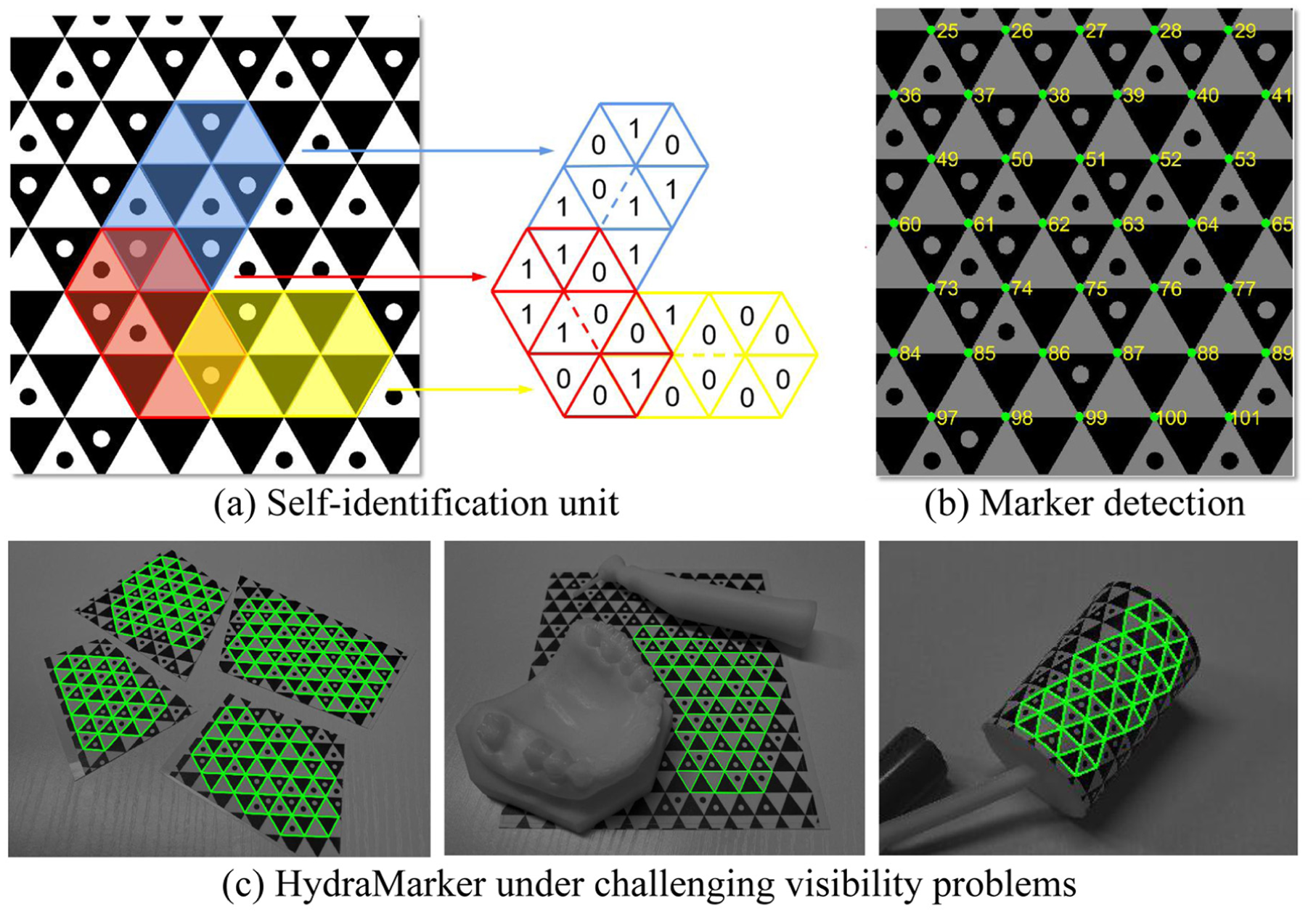
Position-sensing marker: (a) HydraMarker has seamlessly overlapping self-identification units, (b) HydraMarker is detected with individual label on its every cross point, and (c) HydraMarker facing visibility problems: cutting, occlusion, and deformation.
Incremental marker point-cloud reconstruction
A complete feature point model of the marker is key to the marker-based localization method. Simultaneously, it simplifies the pose estimation of the silhouettes in reconstruction from different viewpoints. When a marker is attached to curved surfaces, it is necessary to identify and stitch feature points from multiple views. This paper proposes an adaptive incremental marker reconstruction method, including feature matching, reconstruction, incremental matching of new images, and iterative reconstruction, as shown in Figure 4.
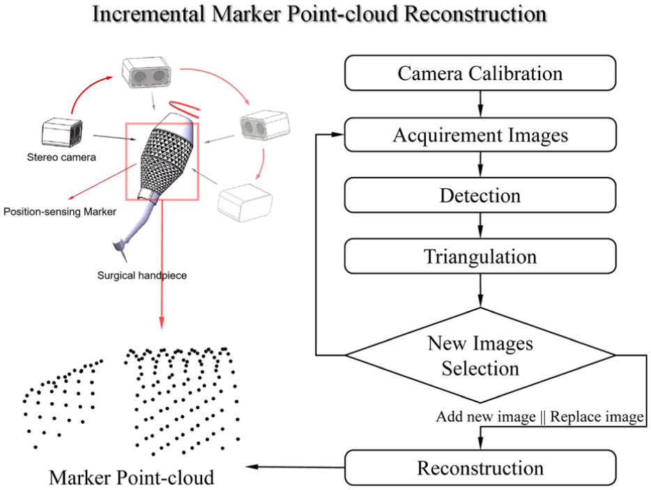
The marker reconstruction illustration and pipeline of our proposed method.
The method consists of two threads: the construction of the image pool and incremental stitching. In the first thread, the images are detected and judged: (1) If an image is blurry or of too poor quality, it will be removed; (2) If a detected image has high similarity to those in the pool, and is of higher quality or contains a greater number of feature points, it will be selected and added to the pool. Therefore, the image pool continuously optimizes its internal quality.
In the second thread, the feature points in the pool are matched and stitched. The image containing the most feature points is used as the primary-image. The sub-images which are images of less feature points than the primary-image, are stitched onto the primary-image. Then, the stitched sub-images are used to match other sub-images for further stitching. In this case, the accumulation of stitching errors can be reduced. Incremental reconstruction continuously adds images of new viewpoints to the image pool, or updates the image quality. The primary-image may be changed during this process, and it continues until the number of marker points reaches saturation.
Silhouette extraction
The proposed method combines the Canny edge detection algorithm 28 with the region growing criterion to extract clean instrument silhouettes. Image acquisition is carried out with a relatively clean background to enhance the silhouette information. Firstly, the image is smoothed using Gaussian Filtering, as shown in Figure 5(a). Then, the edge points of the surgical instrument are preliminarily extracted using the Canny edge detection algorithm.
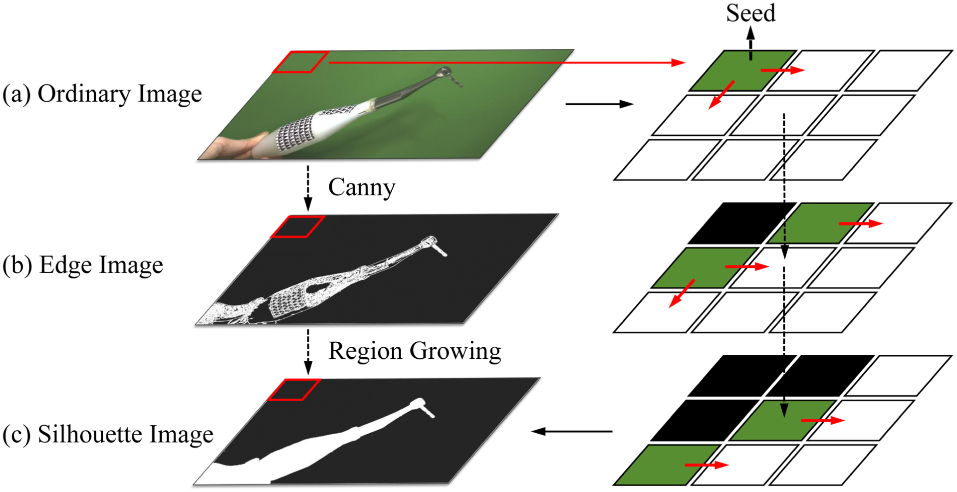
Illustration of silhouette extraction for the surgical instrument.
The surgical instrument silhouette is segmented from the background based on Canny, and its interior is filled using the region growing algorithm. 29 The pixel points at the four corners of the image are selected as seed points, as shown in Figure 5(b). Starting from the initial seeds, similar pixel points are matched from the neighboring pixels based on the intensity similarity criterion, as
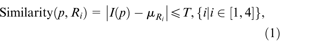
where
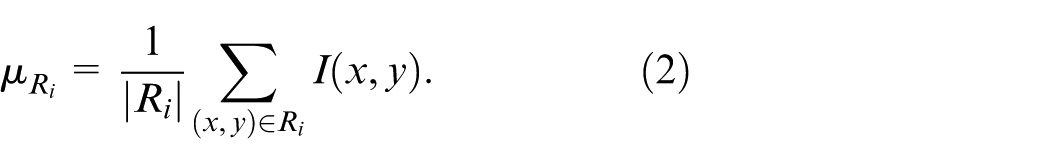
These similar pixels are then recorded and marked as new seeds. The old seeds are recorded as segmented points, and the seed intensity parameter
Full-tool reconstruction
The proposed method reconstructing the surgical instruments is based on the intersection of visual cones in camera’s field of view (FoV), as illustrated in Figure 6(a). In other words, the reconstructed model is formed by the intersection of the visual volumes generated from the silhouettes of each view. Voxel parts outside the silhouettes are carved away based on different silhouettes, gradually restoring the voxel model of the surgical instrument.
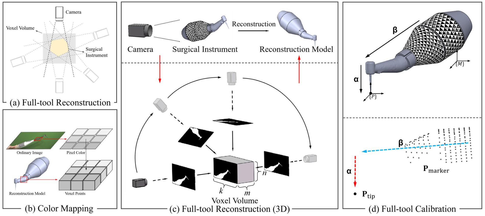
Full-tool reconstruction and full-tool calibration: (a) the 2D illustration of reconstruction, (b) the color mapping of reconstructed model, (c) the 3D illustration of reconstruction, and (d) the illustration of full-tool calibration and geometry illustration of calibration.
Unlike ordinary shape-from-silhouette,
19
we use the multi-level pyramid criterion to control the coarse-to-fine of models. A voxel block of size
The 0 and 1 are used to represent whether a pixel point is inside the silhouette or not. For the silhouette of each view, each voxel point is determined whether inside the silhouette. If a voxel point is inside the silhouette, its level is increased by 1. The level is increased by adding more silhouette images. Different voxel points may be inside different silhouettes or multiple silhouettes, thus these voxels with different levels belong to different pyramid layers.
Selecting different layers within the pyramid can control the coarseness and fineness of the model. It can prevent some voxel points from being cut out due to over-segmented edges. Voxel points excluded by over-segmentation can be compensated by other edge features. The color of each pixel on the instrument images is mapped to the corresponding voxel points, as shown in Figure 6(b).
Full-tool calibration
The stylus-tip calibration of the surgical instrument using fiducial marker is typically performed with the pivot calibration method.
30
For point localization, the stylus-tip point of the instrument is projected onto medical images for surgeons monitor to perform operation. However, for irregular instruments, such as a surgical handpiece, surgeons cannot directly monitor the working direction of instrument without vector localization or a silhouette. The vector direction of implantation
A vector calibration method is proposed based on the instrument’s point cloud, which is reconstructed from full reconstruction. The shell of the instrument point cloud model is extracted by the Convex Hull algorithm. The farthest point on shell, away from the center of the point cloud, is selected to determine the stylus-tip, as
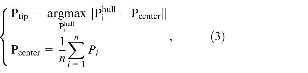
where
Results
Hardware configuration and experimental preparation
In this section, a series of experiments are conducted on the reconstruction, calibration, and localization methods for the surgical instrument. A control group of the pivot calibration method is set to compare with the proposed full-tool calibration. And a control group of the instrument with ArUco-based localization 31 is used for comparation with HydraMarker in occlusion experiment.
A stereo camera is composed of two industrial cameras of Hikvision MV-CS023-10GM (mono,
Marker point-cloud reconstruction
In the preparatory work, the stereo camera is calibrated by stereoCameraCalibration in MATLAB toolbox. The reprojection error in calibration parameter is 0.052 pixels, meeting the accuracy requirement for triangulation. After camera calibration, we fix the surgical instrument on the rotating platform and rotate it arbitrarily, as shown in Figure 7(a). In the first thread, the camera adds new images to the image pool. Each set of left and right images is matched and triangulated, as shown in Figure 7(b). The new 3D point group is judged and selected for inclusion in the image pool based on the triangulation error. In the second thread, the marker point cloud is reconstruction based on the image pool. When the pool is updated, a new incremental reconstruction is carried out, until the marker point cloud model reaches saturation, as shown in Figure 7(c).
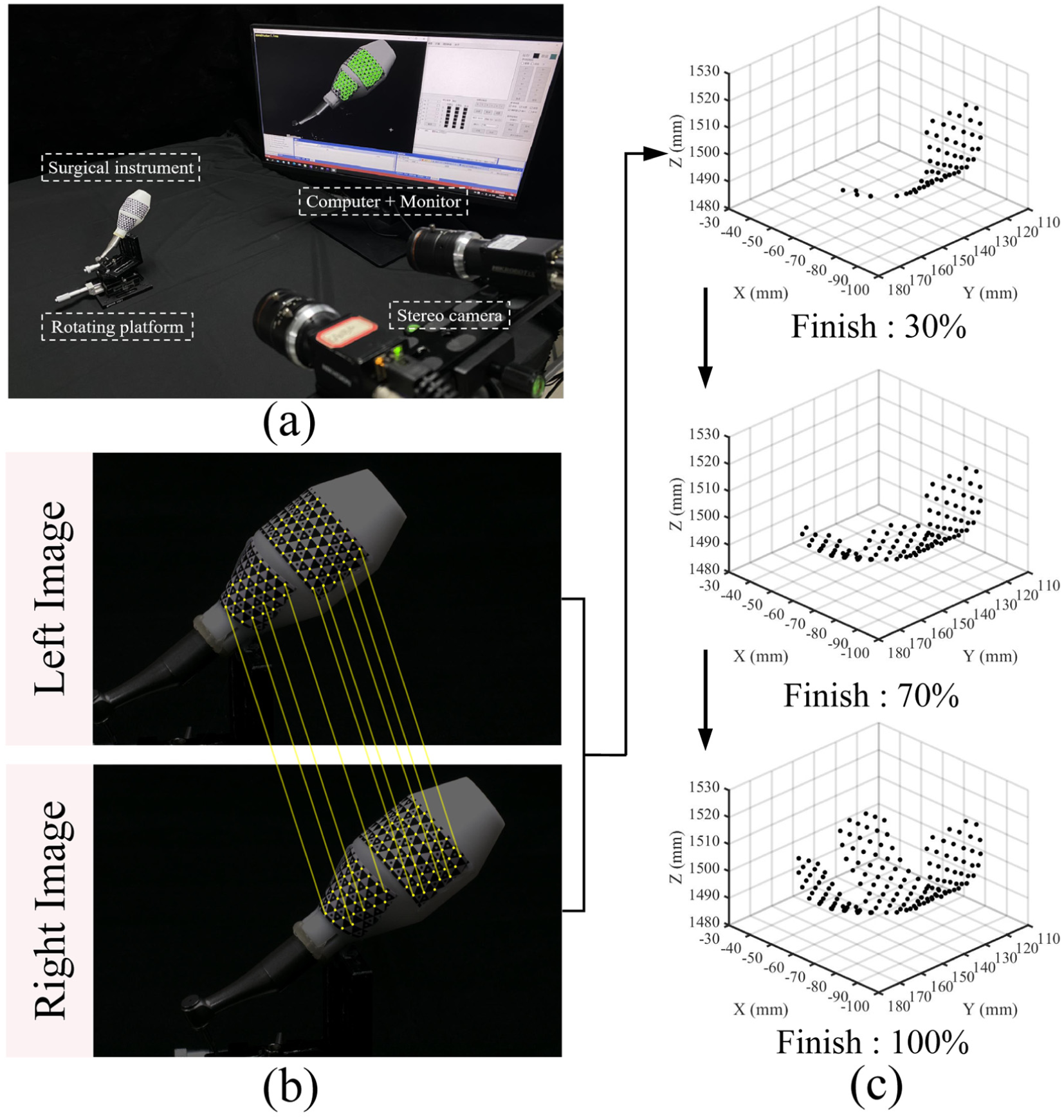
Self-identifying marker spatial model under incremental reconstruction: (a) physical setup of the experiment, (b) feature points on marker under detection, identification, and matching, and (c) incremental reconstruction of different complete degrees.
Silhouette extraction of the surgical instrument
In this experiment, we extract silhouettes from 30 images of the surgical instrument obtained from different viewpoints. Four initial intensity seed parameters are set to compare the extraction efficiency (
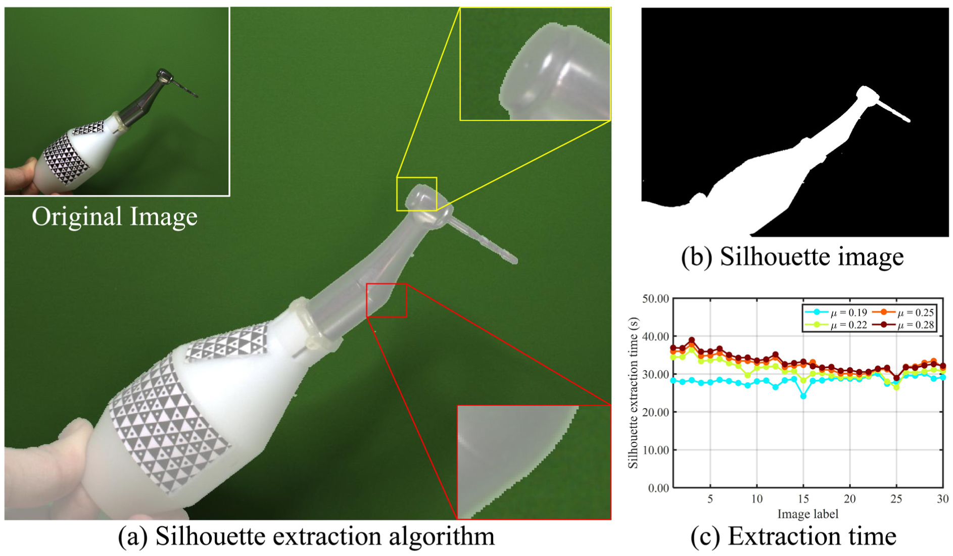
Silhouette extraction: (a) Silhouette image is reprojected onto the instrument image, displaying different detailed parts, (b) the result of extraction, and (c) extraction time cost for different images.
Reconstruction of surgical instrument and silhouette monitoring
In this experiment, we construct a
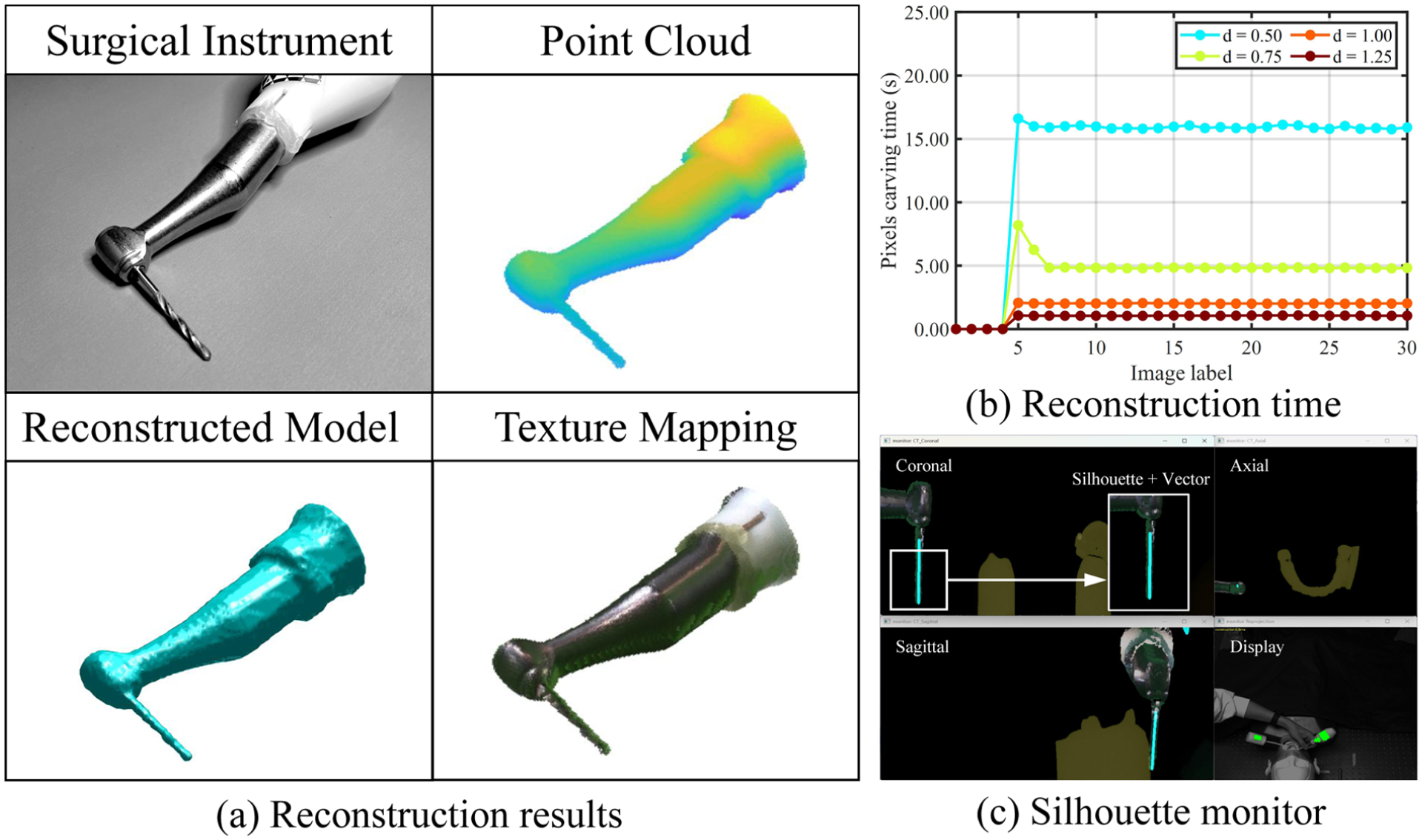
Marker-based surgical instrument reconstruction: (a) the results of voxel point cloud model, reconstructed model, texture mapping model, (b) the reconstructed time cost for different silhouette images under different voxel densities, and (c) the reconstruction model is projected onto medical images.
Instrument calibration and point localization accuracy evaluation
In this experiment, the fiducial registration error (FRE) is used to evaluate the localization accuracy after full-tool calibration, 32 as
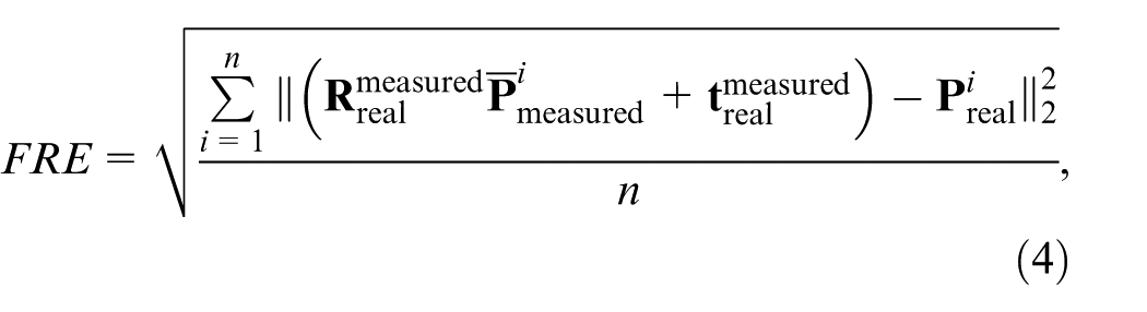
where
We use the instrument’s stylus-tip to position the holes in the localization test block. A
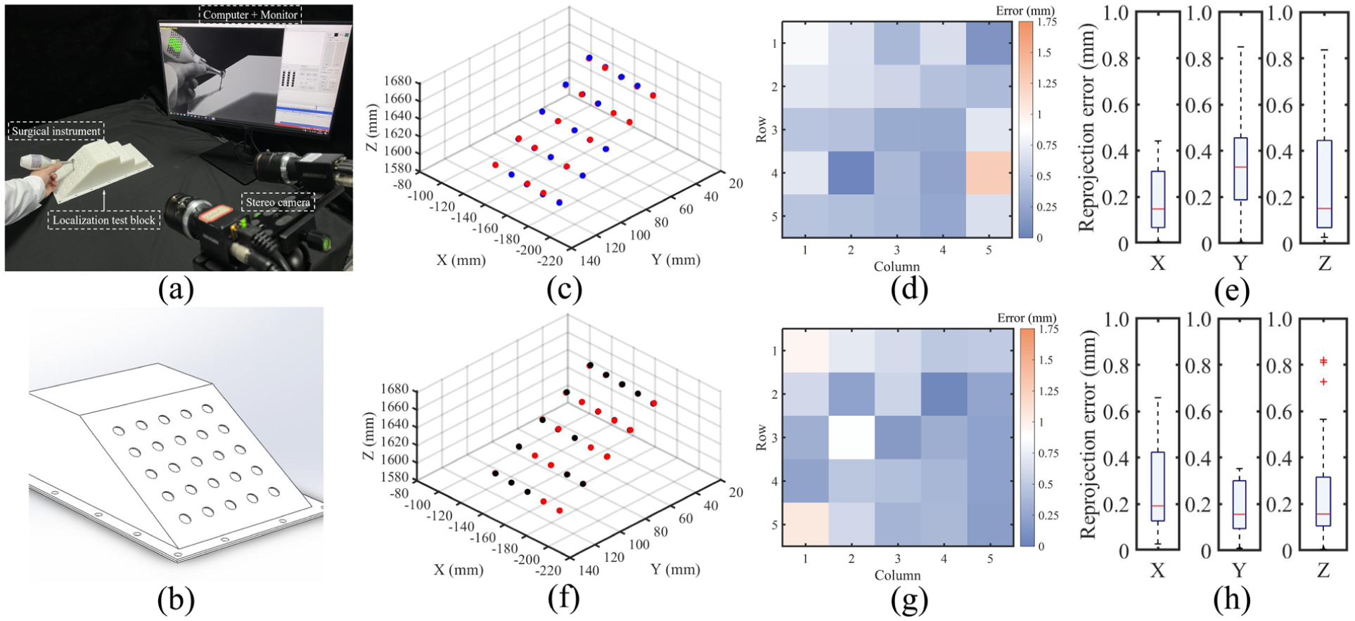
Full-tool calibration of the surgical handpiece: (a) physical setup of the FRE experiment, (b) localization test block model, (c) the result of FRE using our calibration method (The red indicate “actual” coordinates while the blue points indicate the measured points), (d) distance error for each points using our method, (e) accuracy evaluation for X, Y, and Z axis using our method, and (f–h) are measured for the control group (The red indicate “actual” coordinates while the black points indicate the measured points).
Vector localization in orientation accuracy evaluation
In this experiment, the relative orientation error (ROE) is used to evaluate the orientation error in drill implantation.
33
The results of the normal vector of the drill in the hole on the orientation test hemisphere are recorded sequentially, as shown in Figure 11(a). The diameter of the hole

where
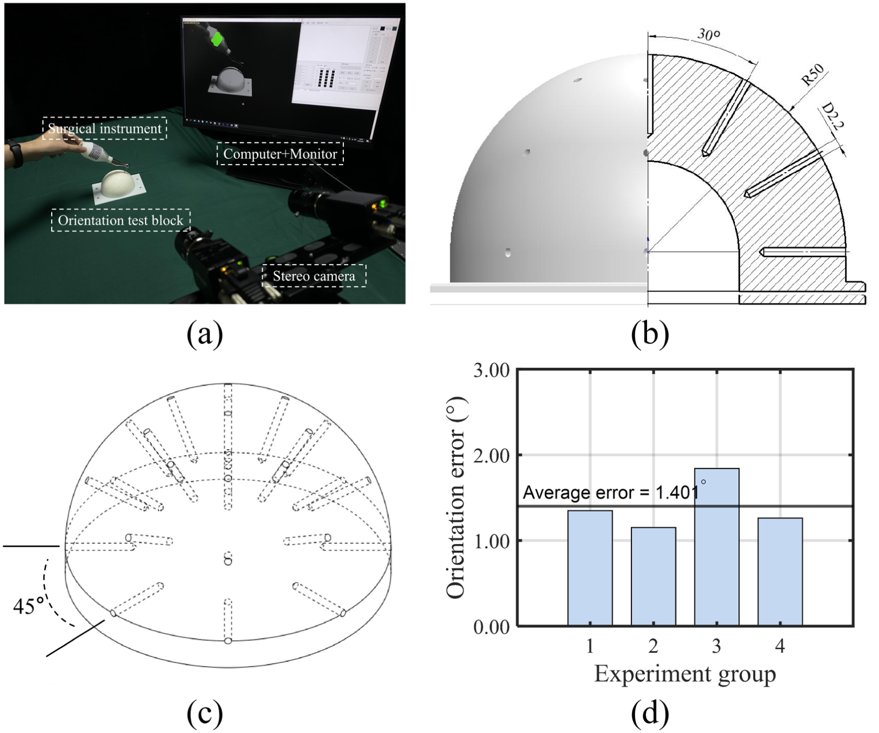
Orientation accuracy evaluation: (a) physical setup of the ROE experiment, (b) hemisphere containing 25 paths, which included angle between two adjacent paths in the same cross section is 30°, (c) hemisphere perspective view with four directions (0°, 45°, 90°, and 135°), and (d) accuracy evaluation in four cross sections and the average ROE.
HydraMarker-based localization and comprehensive effect evaluation
In this experiment, the raster ruler motion platform is used to evaluate the accuracy of HydraMarker-based localization, as shown in Figure 12(a). In the following experiment, different levels of occlusion were introduced, and the localization accuracy was evaluated based on the movement of the surgical handpiece. The occlusion rates were set to 0%, 25%, 50%, and 65%. The ArUco-based instrument localization method was used as the control group for comparative evaluation, as shown in Figure 12(a). Because surgeons typically perform slow and fine instrument manipulations during surgery. The surgical handpiece was fixed on a raster ruler motion platform. The platform was programmed to move in incremental displacements of 2 mm (4 or 8 mm) per step, as shown in Figure 12(b). When using HydraMarker, the localization movement error remained stable and below 0.250 mm under different occlusion conditions. In the absence of occlusion, the movement error reached as low as 0.070 mm at a displacement of 2 mm. Although the error exhibited a slight increase when the occlusion rate exceeded 50%, it remained within an acceptable range. In contrast, when using the ArUco marker, the movement error increased continuously with increasing occlusion levels.
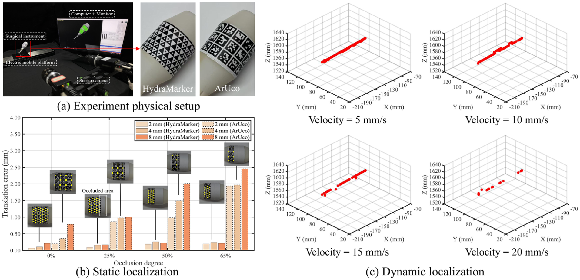
HydraMarker-based localization accuracy evaluation: (a) physical setup of the motion experiment, (b) the distance error result of different occlusion degrees (0%, 25%, 50%, and 65%) under different displacement tests (2, 4, and 8 mm), and (c) the results of dynamic motion tracking under different velocities.
Figure 12(b) shows the results of the two methods for motion error at different distances. In comparison to the control group, our method performs slightly better. The result of the dynamic motion path is shown in Figure 12(c). We set four platform motion velocities to test the tracking performance of HydraMarker-based localization (velocity = 5, 10, 15, and 20 mm/s). Figure 12(c) shows that the tracking performance is good when the velocity is less than 10 mm/s. A part of tracking results are lost at 15 mm/s. When the velocity exceeds 20 mm/s, it is only partially successful. Given that surgical instruments are typically manipulated at low speeds during procedures, our method is well-suited to accurately and reliably track their motion, thereby ensuring effective surgical localization and silhouette monitoring.
Discussion
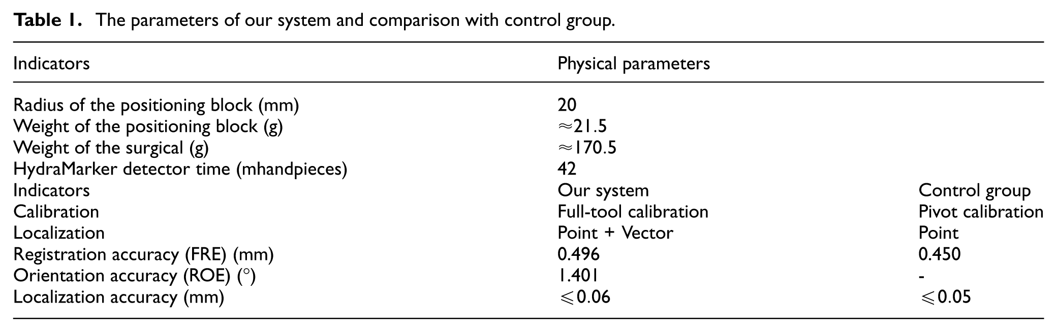
As can be seen from Table 1, the position block is 88% lighter than the surgical handpiece in weight. HydraMarker on the positioning block can be detected and identified on a non-high-performance computer in 42 ms. In our marker reconstruction method, users only hold and turn the instrument to complete the marker spatial point cloud reconstruction. The image pool has an adaptive capability that continuously improves the accuracy of reconstruction. The second thread uses the incremental dendriform reconstruction, which reduces error accumulation caused by splicing in a fixed order.
The parameters of our system and comparison with control group.
Surgical instrument full-tool reconstruction is the key process for enhancing localization performance and the effectiveness of visualization in this paper. In our method, a complete and clean silhouette can be extracted in a non-complexity background. The extraction time for each image on a non-high-performance computer is 30–40 s. Silhouettes with large pose estimation errors are removed. And the reconstruction time on a non-high-performance computer is 100 s. Minor variations in the region-growing intensity threshold primarily affected fine edge details but did not result in catastrophic failures. In addition, the voxel density determines the spatial resolution of the reconstructed model and influences both geometric fidelity and computational cost. These results indicate a resolution–efficiency trade-off rather than a hard threshold. The surgical instrument registration can be performed offline, so the registration time does not occupy the time of the operation.
In experiment, we find that in the localization result of the stylus-tip using our method is similar to that of the control group. For static motion error, our method performs sightly better. In the accuracy evaluation of FRE, the FRE for ours is 0.496 mm, which is comparable to that of the control group. More importantly, we propose a novel calibration method for surgical instrument to calibrate the vector orientation. The average ROE is 1.401°. When using the same fiducial marker, the accuracy of the proposed calibration method is comparable to that of the control group. However, the control group is unable to provide the orientation localization. After camera-to-oral registration, the complete silouette of instrument can be intuitively displayed on the medical image to provide silhouette monitoring for surgeons. In dynamic tracking, HydraMarker-based localization performs better when instrument movements are at 10 mm/s or less. Frequent pose estimation failures were observed at speeds exceeding 20 mm/s. The localization accuracy achieved in the experiment was influenced by the type of marker employed. Owing to the redundancy of the feature-dense position-sensing marker, stable pose estimation was maintained under conditions of moderate partial occlusion. As the occlusion level increased, the localization error increased gradually rather than abruptly.
It should be mentioned that the proposed navigation system is highlighted with a surgical instrument full reconstruction and vector calibration method, but it has some potential limitations. The comprehensive performance is affected by certain configurations and errors, such as the camera performance, the camera calibration error, or computer performance. These are directions of optimization and improvement for the proposed method in the future.
Conclusion
In this paper, we propose a full-tool surgical navigation, including the full-tool registration and HydraMarker-based localization methods. A novel calibration method based on the instrument model is proposed to address the problem of calibrating both the stylus-tip point and directions of the key part on instrument, and we use a feature-dense position-sensing marker as the fiducial marker. Our method provides surgeons with complete localization of the surgical instrument, and a silhouette monitoring overlaid on medical images. Experiments demonstrate that the proposed method achieves localization accuracy similar to point localization using pivot calibration. The fiducial registration error (FRE) of ours is 0.496 mm, and the relative orientation error (ROE) is 1.401°. These results validate the potential of full-tool registration and HydraMarker-based localization. The localization accuracy remain stable using HydraMarker, and it can effectively track the surgical instrument in motion during surgery. After registration, the complete silhouette projected onto medical images provides surgeons with a silhouette monitoring. We plan to further optimize the reconstruction method and calibration methods in future works. We will also develop a novel non-contact registration method based on the proposed full-tool reconstruction method. Clinical experiments on patient are to be conducted in the future, given the consent of patient as well as the positive safety assessment to further evaluate the performances of the proposed method regarding its applicability. Furthermore, we plan to extend the application of full-tool navigation to other surgical instrument geometries in future work, particularly for procedures such as orthognathic osteotomy, where instrument designs differ substantially from dental handpieces.
Footnotes
Ethical considerations
No human participation, patient or clinical data, imagery or material was involved in this study.
Consent to participate
Informed consent was obtained from all individual participants included in this study.
Consent for publication
All participants provided informed consent for the publication of anonymized data and related materials included in this manuscript.
Author contributions
All authors contributed to the study conception and design. Material preparation, data collection and analysis were performed by [Hao Lin], [Bingwei He], and [Mingzhu Zhu]. The first draft of the manuscript was written by [Hao Lin] and all authors commented on previous versions of the manuscript. All authors read and approved the final manuscript.
Funding
The authors disclosed receipt of the following financial support for the research, authorship, and/or publication of this article: This work was supported by the National Natural Science Foundation of China (Grant 62373109), Major Scientific Research Projects in Fujian Province (Grant 2021ZD01003), Joint Funds for the innovation of science and Technology Fujian province (Grant 2021Y9190), Science and Technology Project of Fujian Province (Grant 2021Y0052).
Declaration of conflicting interests
The authors declared no potential conflicts of interest with respect to the research, authorship, and/or publication of this article.
Data availability statement
The data generated and analyzed during this study, including registration parameters and quantitative evaluation results, are not publicly available as they form part of ongoing system development.