
Abstract
This study examines how fabric architecture and hybridization affect the performance of adhesively bonded jute/flax composite joints. Single-lap joints were fabricated using epoxy-bonded composites, including neat jute, neat unidirectional (UD) flax, neat twill flax, and hybrid configurations with a jute core and flax outer layers, and then tested under tensile loading. The results show that fabric architecture significantly influences failure modes. Unidirectional flax fabric promoted controlled failure at the adhesive interface, while twill architectures tended toward delamination. Hybridization with flax substantially enhanced joint performance compared to neat jute. Hybrid joints with UD flax achieved up to 98% of the strength of neat UD flax joints, while twill flax hybrids reached up to 99% of neat twill counterparts. The UD architecture proved superior, showing up to 32% greater strength than equivalent twill flax hybrids. A key finding was that increasing from two to three flax layers provided a marginal strength improvement (<6%), demonstrating that fibre architecture dominates over the number of layers. SEM analysis showed that UD flax hybrids failed mainly by light fibre-tear (LFT), while twill flax hybrids exhibited severe delamination. These results demonstrate that optimal hybridization, particularly with just two UD flax layers, can deliver nearly the full bonded joint performance of neat flax composites while improving material efficiency and lowering cost. The study provides practical design parameters for the development of high-performance, sustainable natural fibre composite joints.
Introduction
The search for materials with a good strength-to-weight ratio has been increasing in various sectors such as automotive, aerospace, civil engineering, marine, and others. These sectors require solutions that reduce structural weight without drastically compromising performance, especially in a scenario where energy efficiency and sustainability are increasingly valued. In addition to structural optimization, there is growing concern about reducing carbon footprints and promoting greater sustainability. In this context, natural fibre reinforced composites (NFRCs) emerge as a promising alternative, combining mechanical performance with characteristics such as biodegradability, low cost, recyclability, and lightness.1–3
Among the widely studied natural fibres, flax and jute stand out. Flax, in particular, has gained space in the global industry due to its good mechanical properties, such as high strength and stiffness, when compared to other natural fibres, controlled industrial production, and scalability.4,5 Jute, known for its wide availability and low cost, exhibits adequate mechanical properties and has shown potential as reinforcing materials for reinforcing composites. 6 However, challenges such as moisture absorption and property variability limit their large-scale application. Despite these limitations, hybridization strategies combining different natural fibres have emerged as a promising route to overcome mechanical drawbacks and expand application possibilities. Fibre hybridization techniques (combining natural/synthetic fibres in interlaminar/intralaminar configurations) have been used to enhance composite performance, including in the adhesive joints.7–9 As a result, extensive research efforts are being directed toward the development of hybrid composites by combining different natural fibres with varying properties, resulting in a material with enhanced performance.7,10 Recent studies have investigated the influence of flax and jute fibre hybridization in various laminate architectures, considering factors such as stacking sequence, fabric types, fibre treatments, and manufacturing methods, among others. The results indicate that the appropriate combination of these fibres can significantly improve mechanical strength and impact resistance, making hybrid composites viable options for advanced structural applications.5,11–17
In the development of composite materials, in addition to optimizing mechanical properties, it is essential to consider bonding mechanisms, especially in more complex structural applications. It is widely acknowledged in the literature that structural adhesion is the ideal joining method for composite materials, and it stands out for its ability to distribute stresses uniformly, minimize material damage, absorb vibrations, and bond different types of substrates.18,19 The performance of bonded joints in natural fibre reinforced and hybrid composites has been studied in literature by several researchers.20–27 Despite advancements in flax and hybrid natural fibre composites, a critical gap remains in understanding the performance and failure mechanisms of adhesively bonded joints specifically incorporating novel flax/jute hybrid architectures under varying layer configurations. Currently, the influence of fabric mesoscale geometry (e.g., unidirectional vs twill) on the interfacial stress distribution and resulting failure modes in such hybrid systems has not been comprehensively addressed in the literature. For example, Ramakrishnan et al. 28 investigated the feasibility of a hybrid structure formed by bonding a thin layer of stainless steel to a flax composite. They used two different matrices for the flax composite: epoxy and PLA and tested the bond strength using epoxy and natural rubber adhesives. The tests showed that the epoxy joint exhibited higher strength, with failure occurring in the adherend, while rubber resulted in adhesive failure, a behavior observed in both the flax/PLA and flax/epoxy composites. Despite showing lower shear resistance, the rubber layer exhibited ductile characteristics, indicating potential for energy absorption applications. In a similar context, Tazi et al. 29 evaluated the interface adhesion of flax fibre composite patches bonded to steel using epoxy, polyurethane, and bio-based polyurethane adhesives. Their results showed that polyurethane adhesives provided superior peel resistance and cohesive failure, highlighting the potential of flax composites in combination with alternative adhesives for structural reinforcement. Kaushik and Singh 30 investigated the performance of single-lap joints of flax/PP laminated composites, considering mechanical joints, fusion (ultrasonic welding and hot plate welding), and hybrid (mechanical/ultrasonic and mechanical/hot plate). The results showed that mechanical joints with two screws exhibited a 48.36% higher failure load than those with a single screw, while the use of larger diameter screws increased the failure load by 9.03%. Among all configurations, the mechanical/ultrasonic hybrid joint achieved the highest failure load (2.94 kN). However, when two screws were applied in the hybrid joints, the resistance did not increase due to the reduction of the bonded area. Failures in fusion and hybrid joints were predominantly structural, meaning the joint itself remained stronger than the adherends, whereas mechanical joints failed by net tension through the hole. Ultrasonic welding outperformed hot plate welding, attributed to greater polymer chain interdiffusion above the PP melting temperature.
In a recent study on adhesively bonded natural fibre-reinforced composite joints, Oliveira et al. 27 demonstrated that flax-based adherends consistently outperformed bamboo in load-bearing capacity, a behaviour attributed not only to the superior in-plane stiffness of flax laminates but also to their more favourable failure mechanisms, dominated by thin-layer cohesive (TLC) and light-fibre tear (LFT) modes rather than widespread delamination. Moreover, the authors showed that the internal architecture of flax fabrics plays a decisive role in joint efficiency: a difference of approximately 32% in failure load was observed between Twill and Biax configurations, evidencing the strong coupling between fabric mesoscale geometry, interfacial stress distribution, and resulting failure behavior.
Other studies on bonding using flax as reinforcement can be found in the literature. However, the focus of these studies is on evaluating the behavior for applications in other industries, such as construction.31–33 This gap in literature is significant, considering that flax presents promising properties, such as high strength and stiffness, which can benefit the performance of adhesive joints in more advanced structural applications. Addressing this gap is crucial, as it directly impacts the development of lightweight, sustainable, and structurally reliable bonded systems for advanced engineering applications. Therefore, the present study aims to investigate the mechanical performance of single-lap adhesive joints (SLJs) using hybrid composites reinforced with natural fibres, specifically jute and flax. This work provides a unique contribution by systematically elucidating the role of the external fabric architecture (unidirectional vs twill) in governing interfacial stress transfer and the resulting failure-mode transition in jute/flax hybrid SLJs, demonstrating that optimal joint efficiency can be achieved with a minimal number of high-performance flax layers. To the best of the authors’ knowledge, this is the first study to investigate how flax outer-layer architectures influence the balance between mechanical integrity and material efficiency in jute/flax hybrid adhesive joints. To this end, hybrid composite substrates were fabricated, consisting of a core of five layers of jute and different external architectures containing unidirectional and twill flax fabrics. Single-lap adhesive joints using a general-purpose two-component epoxy adhesive were fabricated and tested through tensile testing. Failure modes were analyzed visually and using scanning electron microscopy (SEM) according to ASTM standards. Based on the results obtained, this study seeks to expand knowledge about the influence of hybridization on the efficiency of adhesive joints in natural fibre reinforced composites. The experimental investigation will provide insights into future structural applications, demonstrating the potential of hybrid jute and flax composites as sustainable and viable alternatives for sectors seeking reduced structural weight and greater sustainability without compromising the mechanical integrity of structures bonded by adhesion.
Materials and methods
Materials
Basic parameters of fabrics a .
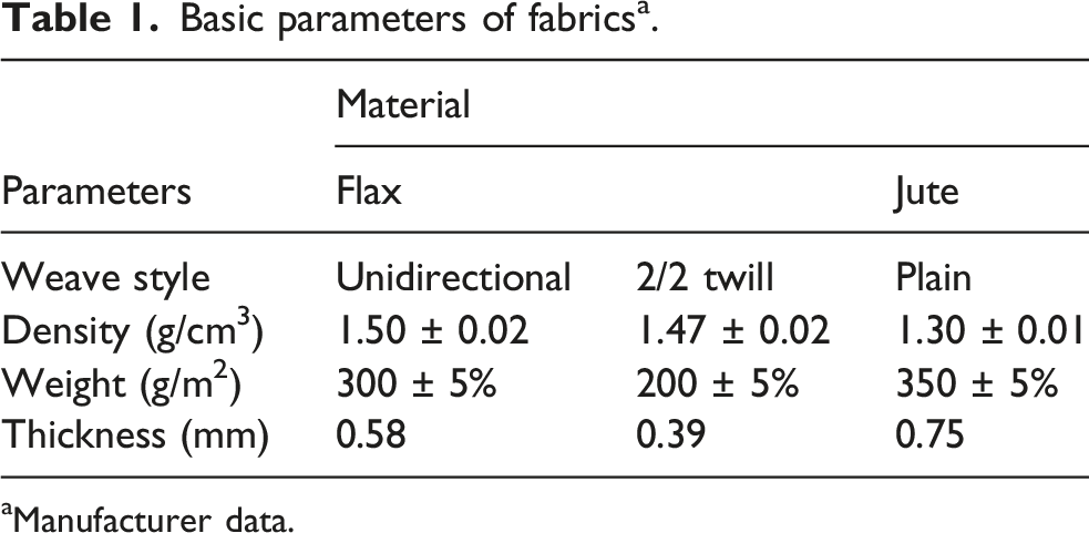
aManufacturer data.
Tensile data of the resin and adhesives 34 .
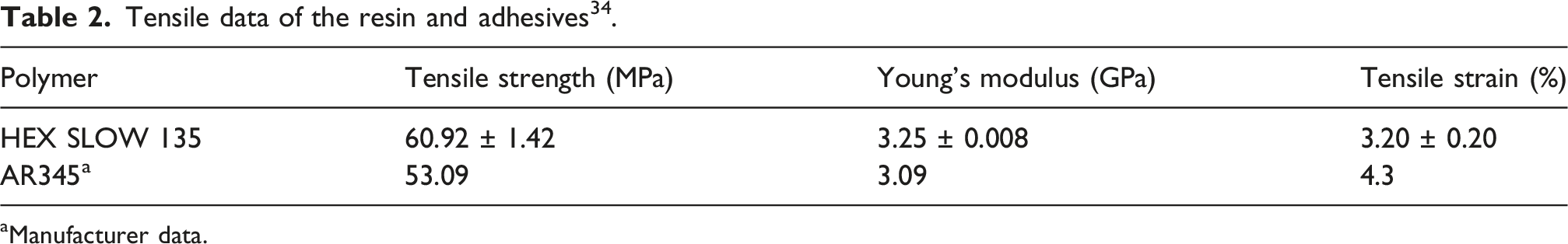
aManufacturer data.
Substrate specimen fabrication
The composite plates were fabricated using the compression molding technique with a steel mold and a heated hydraulic press (Solab SL-20, São Paulo, Brazil). The resin system used was HEX 135 SLOW, with a resin/hardener weight ratio of 100/33. The detailed process fabrication can be found in a previous study.
35
A summary of the fabrication method is presented as follows (see Figure 1): Initially, the fibre fabrics were cut to dimensions of 220 × 150 mm. A drying process of the fabrics was carried out to remove moisture, the fabrics underwent heat treatment in a muffle furnace at 100°C for approximately 15 min until a stable weight was reached. After this, the lay-up process was then carried out manually by placing a fabric layer onto a metallic mold, followed by the uniform application of resin using a roller. This process was repeated until all fibre layers were impregnated with resin. To ensure thickness uniformity and minimize void formation, metal spacers, silicone, and polyurethane adhesive tape were used. The metallic mold, containing the laminated fibre layers, was then placed in a heated hydraulic press, where the curing process was performed at 75°C under 30 MPa pressure for 8 h, following the resin manufacturer’s recommendations. After curing, the composite plates were cooled under pressure before removal from the mold. The fabricated composite plates were then cut into specimens using a mini circular saw, with the substrates cut to dimensions of 25 mm × 107.5 mm. Schematic of composite plate manufacturing process.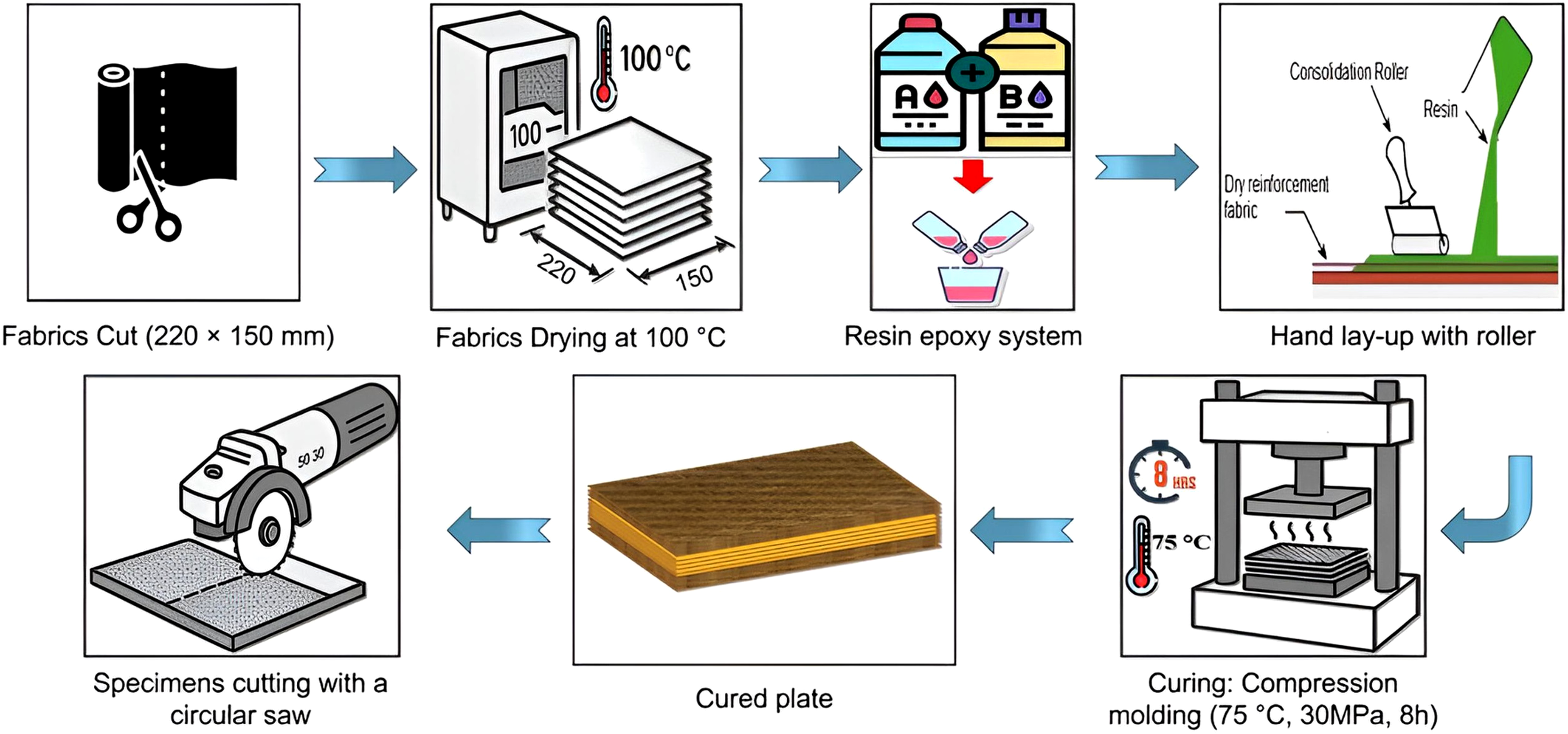
Nomenclature of the specimens as a function of material and reinforcement.
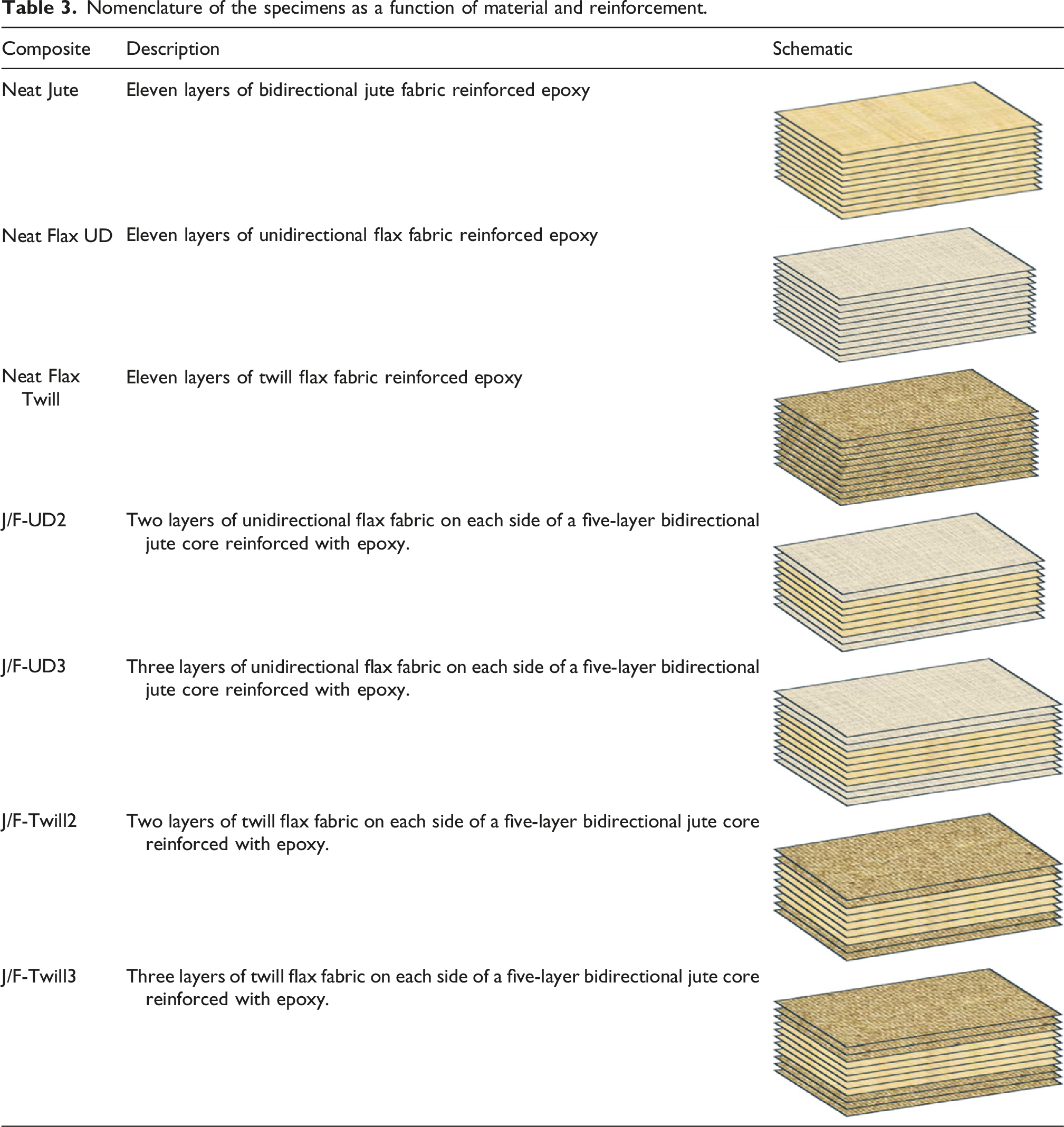
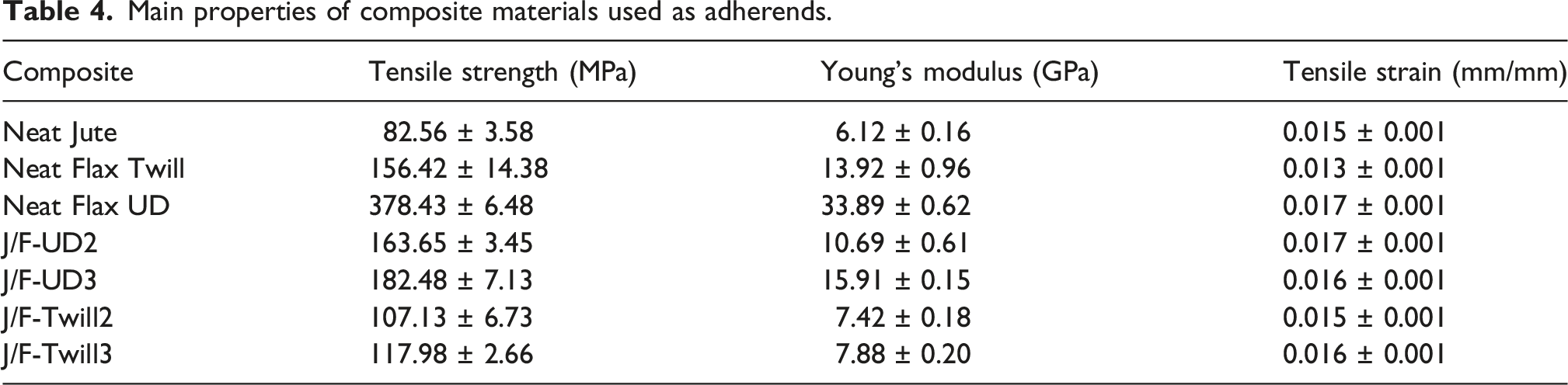
The fibre weight content in the hybrid composites was maintained at approximately 50% for the samples reinforced with twill flax and 55% for the samples reinforced with unidirectional (UD) flax, while the resin + hardener system accounted for the remaining mass of the final composite. The mass ratio between jute and flax in the hybrid J/F-Twill2, J/F-Twill3, J/F-UD2, and J/F-UD3 composites were approximately 65/35, 60/40, 60/40, and 50/50%, respectively. For the neat composites reinforced with twill and UD flax fibres, the fibre content was maintained at approximately 50% and 70%, respectively. As for the neat jute sample, the fibre content was kept at approximately 50%. The plate thicknesses were approximately 4 mm for the hybrid flax/jute samples, 3 mm for the neat samples reinforced with twill flax or UD flax, and 5 mm for the neat jute samples. It is important to note that the laminate configurations investigated in this study involve concurrent variations in fabric architecture, thickness, and fibre content, arising from the intrinsic physical characteristics of the fabrics employed. Although these parameters are inherently interrelated in practical hybrid laminate designs, all joints were manufactured using symmetric adherends to ensure balanced stiffness and geometric consistency within each configuration. Therefore, the adopted experimental approach still provides a consistent basis for assessing the predominant influence of UD and twill flax architectures on joint mechanical performance and failure behavior. Figure 2 shows the representative tensile stress–strain curves of all the materials used as adherends, while a summary of their main properties is presented in Table 4. These composite properties were previously characterized in a previous study by the authors,
35
which provides additional details supporting the values reported here. Representative tensile stress–strain curves of all the materials used as adherends as a function of flax woven architecture: (a) Flax twill and (b) Flax UD. Main properties of composite materials used as adherends.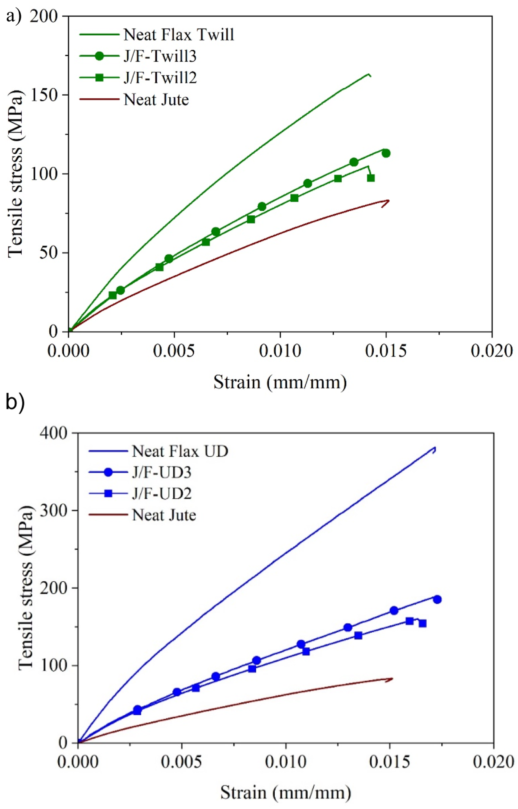
Single-lap joint specimen fabrication
The schematic geometry of the SLJ specimens is shown in Figure 3. Schematic of bonded joint specimen (dimensions in mm).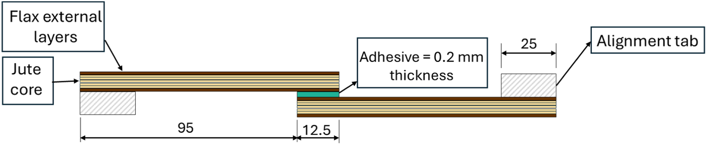
The single lap joints (SLJ) were fabricated according to the ASTM D5868 36 standard. The adherends were cut to dimensions of 107.5 mm × 25 mm, and their bonding surfaces were mechanically treated with 100-grit sandpaper at a +45°/−45° angle relative to the longitudinal axis. This abrasion aimed to increase the surface roughness, improving the mechanical interlocking between the adhesive and the adherend. The sanding residues were removed using compressed air and 99% alcohol, followed by thorough cleaning with 99% acetone to degrease the surface and minimize adhesive failures. 18
An aluminum mold and steel spacers were used to ensure alignment during fabrication. The epoxy adhesive used was a two-component system mixed in a 100:45 weight ratio, following the manufacturer’s recommendations. After homogenization, the adhesive was manually applied to the bonding area, ensuring uniform distribution and minimizing void formation. The adhesive layer thickness (0.2 mm) and overlap length (12.5 mm) were controlled using steel spacers, preventing the formation of spew fillets (see Figure 4). After assembly, the mold was closed and fixed to apply the necessary pressure for curing. The joints were cured in a hydraulic press at room temperature for 24 h. Alignment pads were fixed to the adherends to minimize bending moments during tensile testing. Any excess adhesive expelled during curing was removed by post-curing abrasion to avoid interference with the mechanical performance of the joints.
37
Schematic of composite bonded joint fabrication.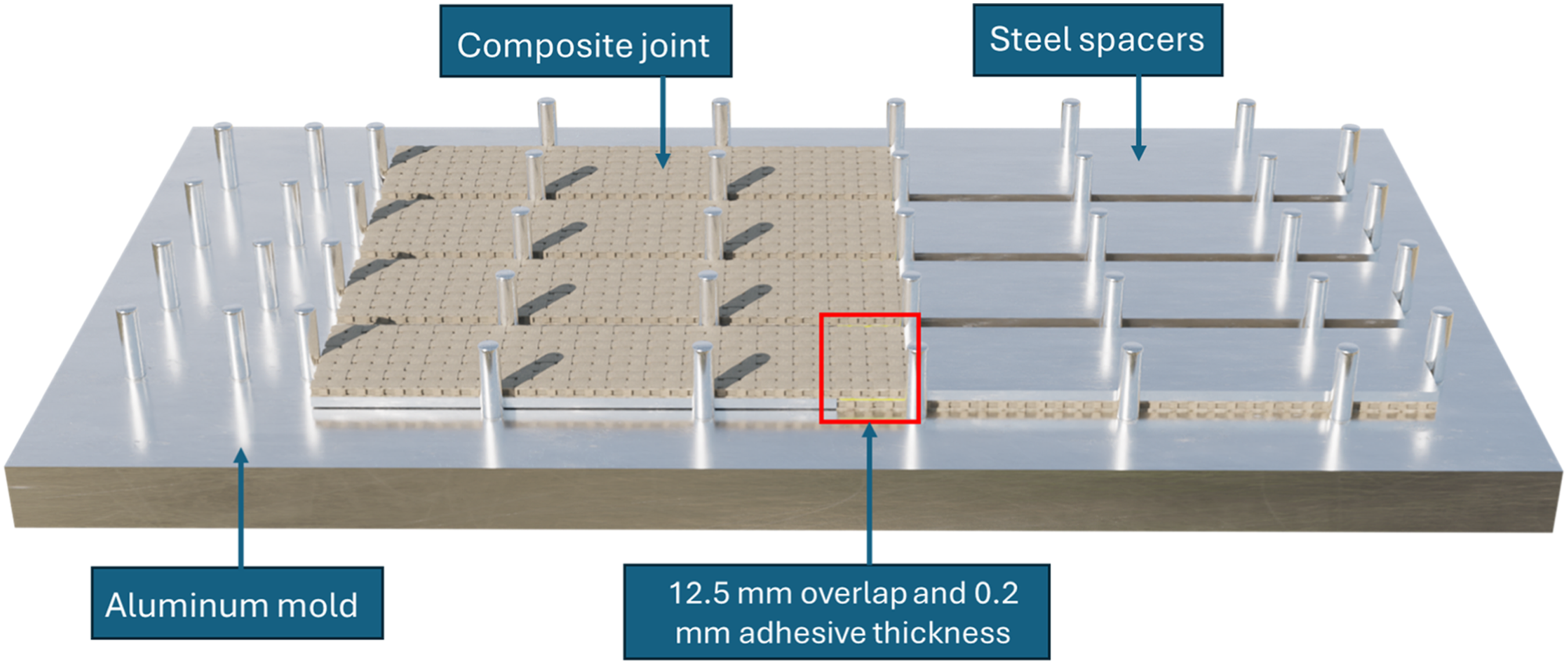
Measurements and characterization
The SLJs were tested in traction using an Instron® 5966 universal testing machine (Norwood, Massachusetts, USA), equipped with a 10 kN load cell. The tests were conducted at a crosshead speed of 1 mm/min. Four specimens were tested for each group at room temperature. To ensure proper alignment of the bonded area in the grips, shims with dimensions of 25 mm × 25 mm were placed at the grip areas, as can be seen in Figure 5. After the tests, tensile data and load-displacement curves were extracted for analysis and discussion in the results. Example of the SLJ test set-up.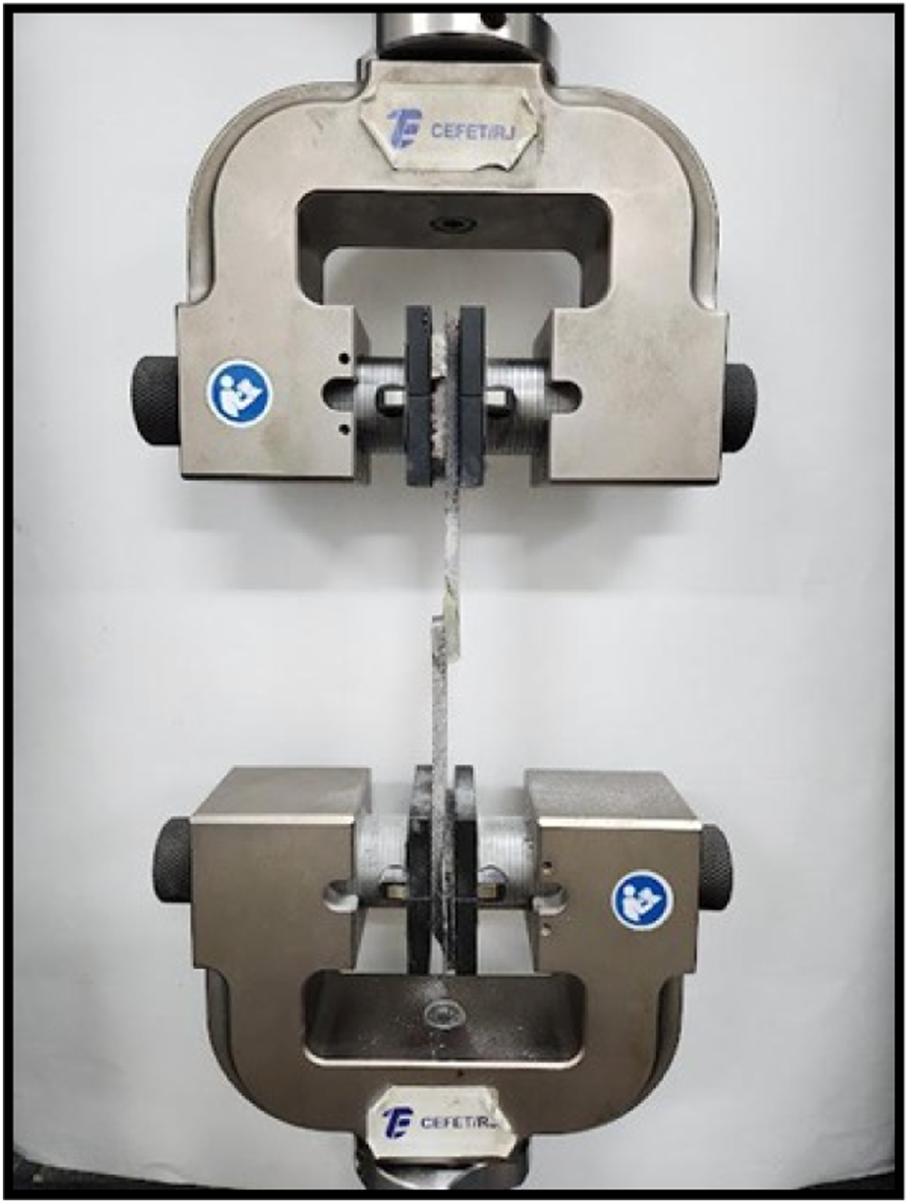
For the analysis of fracture surfaces, scanning electron microscopy (SEM) was employed using a TM4000Plus Hitachi microscope (Tokyo, Japan) operated at 15 kV. All analyses were performed under low-vacuum conditions, and the samples were not metal-coated.
Results and discussion
Joint failure modes
The failure process of adhesively bonded composite joints is highly complex. According to the international standard ASTM D5573, 38 the failure modes of these joints can be categorized into seven types: (1) adhesive failure, (2) cohesive failure, (3) thin-layer cohesive failure (TLC), (4) fibre-tear failure (FT), (5) light-fibre-tear failure (LFT), (6) stock-break failure (SB), and (7) mixed failure (i.e., when two or more failure modes are present). After examining all the fractured specimens, three main failure modes were identified: fibre-tear failure, light-fibre-tear failure and stock-break failure. Fibre-tear failure, also known as delamination, involves a more severe and widespread removal of fibres and bundle failures. LFT is characterized by a thick adhesive layer on one side, with no adhesive on the other, along with some surface resin and a few fibres removed from the interface. Stock break failure refers to total failure of the adherend material. Mixed failure modes are common for NFRCs as well as natural/synthetic hybrid composite joints, due to the complex stress state of the overlap zone.21–26
Figure 6 presents the representative failure modes for the joints studied. From Figure 6(a), it can be seen that the failure mode of the Neat Jute SLJs was a stock break failure. This failure occurs at the exact end of the overlap of one of the joint ends and is because jute fibres and their composites are more brittle.22,24 Consequently, the JFRP is less able to rotate its edges to accommodate the increasing peel stress caused by load eccentricity in an SLJ shear test. Figure 6(b) and (c) show the J/F-UD2 and J/F-UD3 SLJs failure modes, where a widespread light fibre-tear failure (LFT) can be seen. For the J/F-Twill2 and J/F-Twill3 SLJs (see Figure 6(d) and (e)), a widespread fibre tear (FT) or delamination failure can be observed. Finally, it is possible to observe in Figure 6(f) and (g), that the failure modes of the flax neat SLJs, (i.e., Neat Flax Twill and Neat Flax UD), presented a widespread FT and LFT failure mode, respectively. In general, the main difference in failure modes was due to the flax fabric architecture, with failures closer to the interface in the UD flax joints (neat and hybrids) and generalized delamination in the Twill flax joints (neat and hybrids). Representative adhesive joint failure surfaces: (a) Neat Jute (top and side view); (b) J/F-UD2; (c) J/F-UD3; (d) J/F-Twill2; (e) J/F-Twill3; (f) Neat Flax Twill and (g) Neat Flax UD.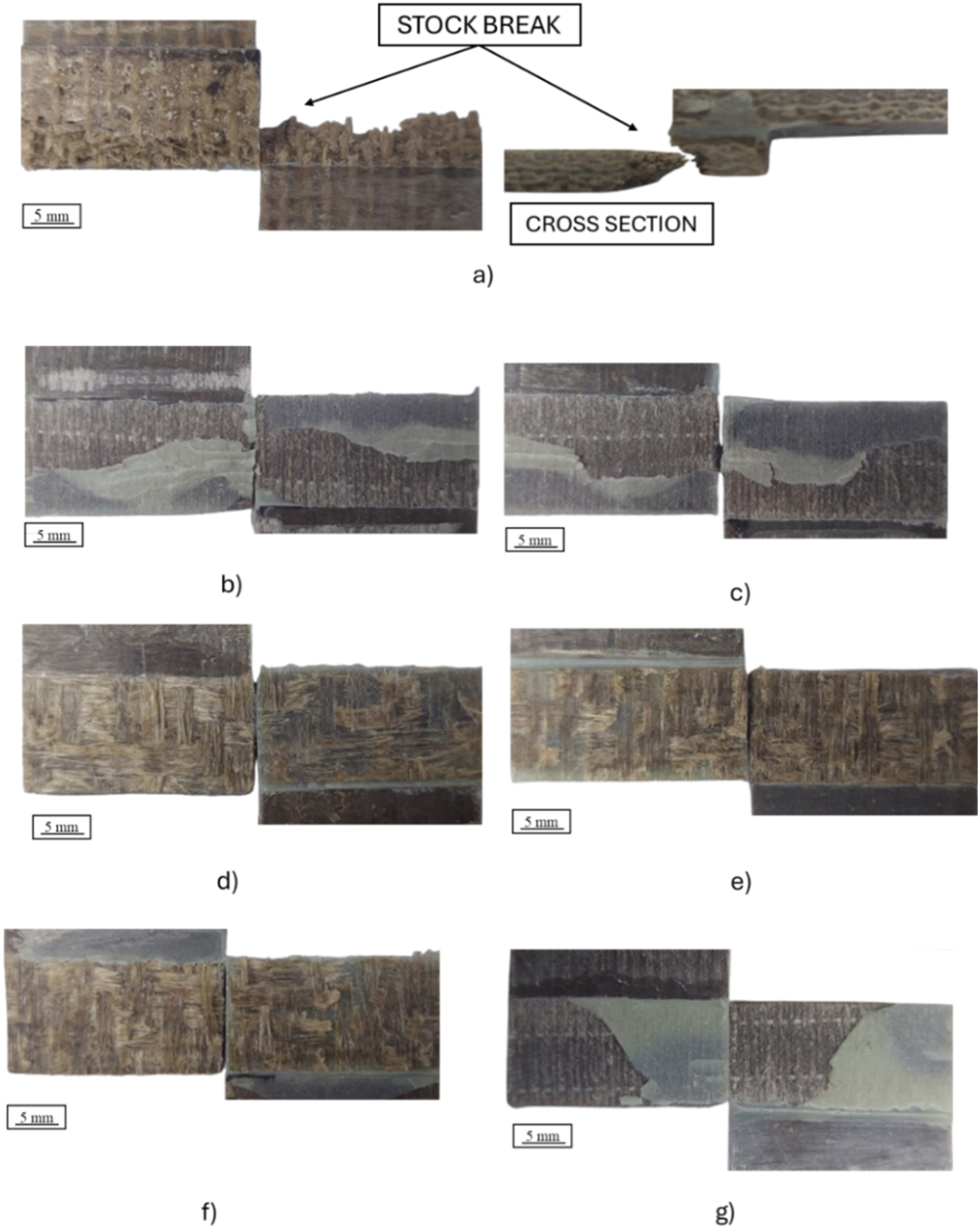
In order to investigate the fracture mechanisms and fracture surface morphology, a SEM analysis of the fractured bonded areas was performed on Neat Flax Twill and Neat Flax UD SLJs. Representative SEM micrographs of the adherend surfaces after failure are presented in Figure 7. Since the failure modes were similar between the pairs (i.e., LFT in the UD flax-reinforced samples and generalized delamination in the twill flax-reinforced samples), the failure modes of these SLJs will be used to further discuss the general failure modes. From Figure 7(a), the fracture of the Neat Flax Twill SLJ shows severe and widespread delamination, with multiple layers removed and failures in some fibre bundles. This was the predominant failure mode for all flax twill SLJs. Figure 7(b), on the other hand, illustrates the fracture of the Neat Flax UD SLJ, where the failure mode was dominated by light fibre-tear (LFT). Resin removal from the adherend, fabric and fibre imprints, along with the superficial delamination of a fibre in the thick adhesive layer on the adherend’s right side, can be observed. Detailed macrographs of the representative failure surfaces of (a) Neat Flax Twill and (b) Neat Flax UD.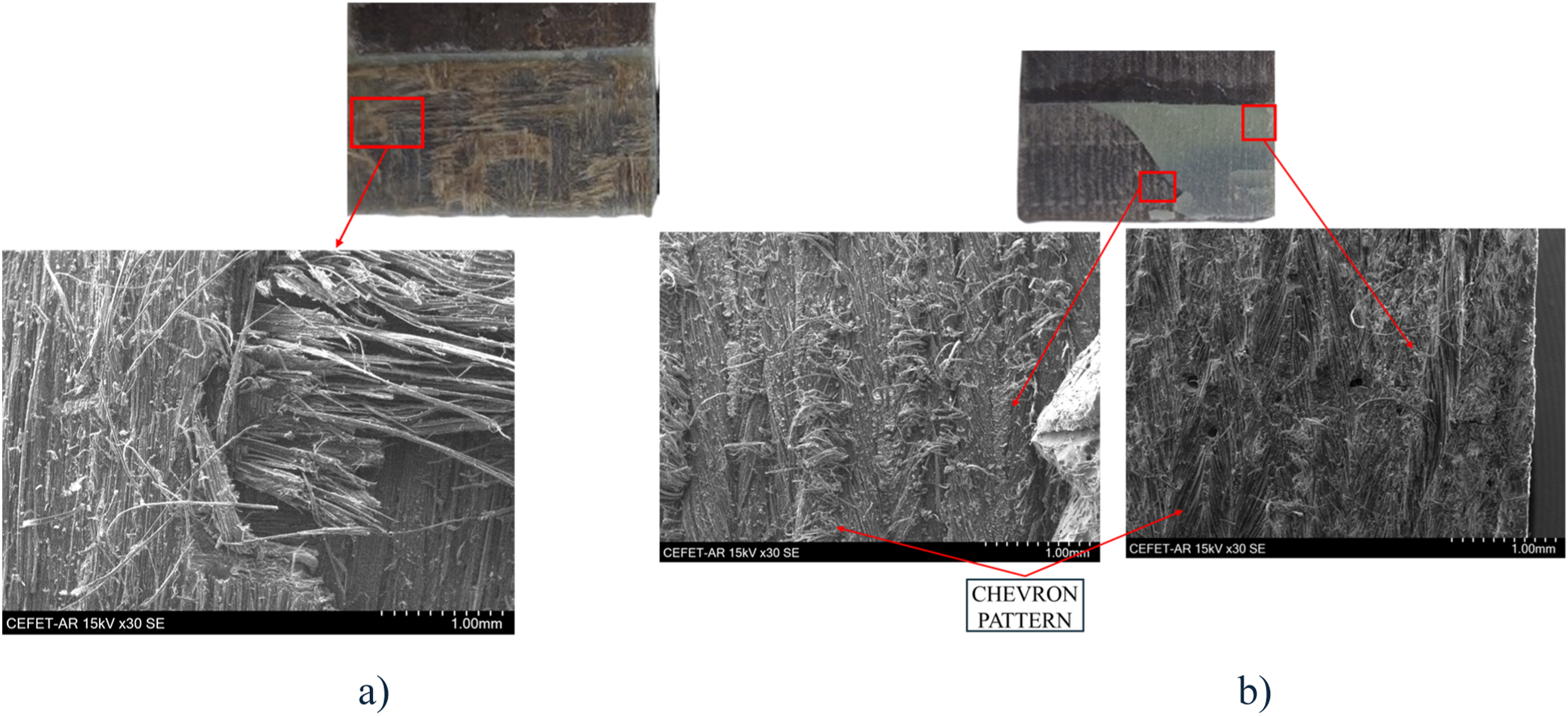
This study suggests that the architecture of flax fabrics used as reinforcement, namely UD and Twill, influences crack development and, consequently, the failure mode of the joints. For example, in SLJs with flax UD fibre-reinforced substrates (see Figure 7(b)), which exhibit a compact fabric of twisted yarns aligned in a single direction, the resin content between the yarns tends to be reduced, thereby increasing the effective contact area between the yarns and the matrix, as previously demonstrated in the literature. 39 Additionally, fabrics oriented at 0° help prevent crack propagation into deeper regions of the substrate. As a result, the crack tends to follow the path of least energy dissipation, occurring in the resin or at the resin/fibre interface, as shown in the literature.40,41 Thus, when the applied load on the joint reaches a critical point of plastic deformation of the resin, the crack initiates at one of the adhesive/resin interfaces of the adherend. Being unable to penetrate further, it develops superficially within the resin, removing it almost entirely along with some residual fibres from the first layer. This results in a generalized LFT failure in all SLJs with flax UD adherends. Additionally, a chevron-like pattern is observed in the adhesive layer of one of the adherends, resulting from the imprint of the fibres from the first layer of the other adherend. This pattern is due to the twisting of the unidirectional fabric fibres (see Figure 7(b)).
On the other hand, in SLJs with flax twill fibre-reinforced substrates (see Figure 7(a)), the bidirectional structure of the twill fabric directly influenced the failure behavior. In this configuration, the warp fibres, aligned with the principal direction of the external load, bore most of the applied tension, while the weft fibres, oriented at 90° to the load, were more susceptible to debonding due to rotation. This facilitated the pull-out of the weft fibres due to the complex stress field in the overlap, particularly the high peel stresses at the overlap edges. The pull-out of the weft fibres from the first layer created vulnerable zones that allowed the crack to penetrate between the composite layers. As the crack advanced, the interaction between the debonding stresses and the fabric structure intensified the propagation of delamination more broadly. The result was generalized delamination, as observed in all SLJs with twill flax fabric-reinforced adherends.
Some studies demonstrate how the orientation of the lamina adjacent to the adhesive layer influences the determination of the failure mode of single-lap joints (SLJs). It was shown in the literature that the orientation of the lamina in contact with the adhesive layer can significantly influence the failure mode in single-lap joints (SLJs).39,42 A 0° interface ply resulted in cohesive fracture within the adhesive layer, which could occur near the contact region between the adhesive and the adherend resin. On the other hand, a 90° interface ply led to crack propagation into the composite adherend, following a predominantly intralaminar path. Additionally, it was observed that the crack tends to stop when reaching the first 0° ply, indicating that the presence of fibres oriented in this direction helps to restrict crack propagation within the composite. Sadeghi et al. 43 investigated the failure modes in E-glass/epoxy composite adhesive joints, focusing on the effect of the fibre angle adjacent to the semi-rigid adhesive layer. Experimental results and numerical analysis indicated that increasing the fibre angle from 0° to 90° significantly altered the failure modes. For the 0° angle, failure occurred predominantly at the adhesive interface, with cohesive fracture of the adhesive layer. As the angle increased, failure shifted towards the composite interior, propagating intralaminarly. A similar relationship was reported by Oliveira et al., 27 who showed that configurations promoting controlled, interfacial or near-interfacial fracture (TLC/LFT-type) tend to maintain crack propagation confined to the adhesive–adherend interface, while architectures prone to deeper fibre–resin damage or heterogeneous fracture favour unstable intralaminar propagation. Overall, flax architectures that constrain the crack path to the interface delay the onset of severe delamination and promote more stable failure progression.
Effect of woven architecture and hybridization on the bonded joint efficiency
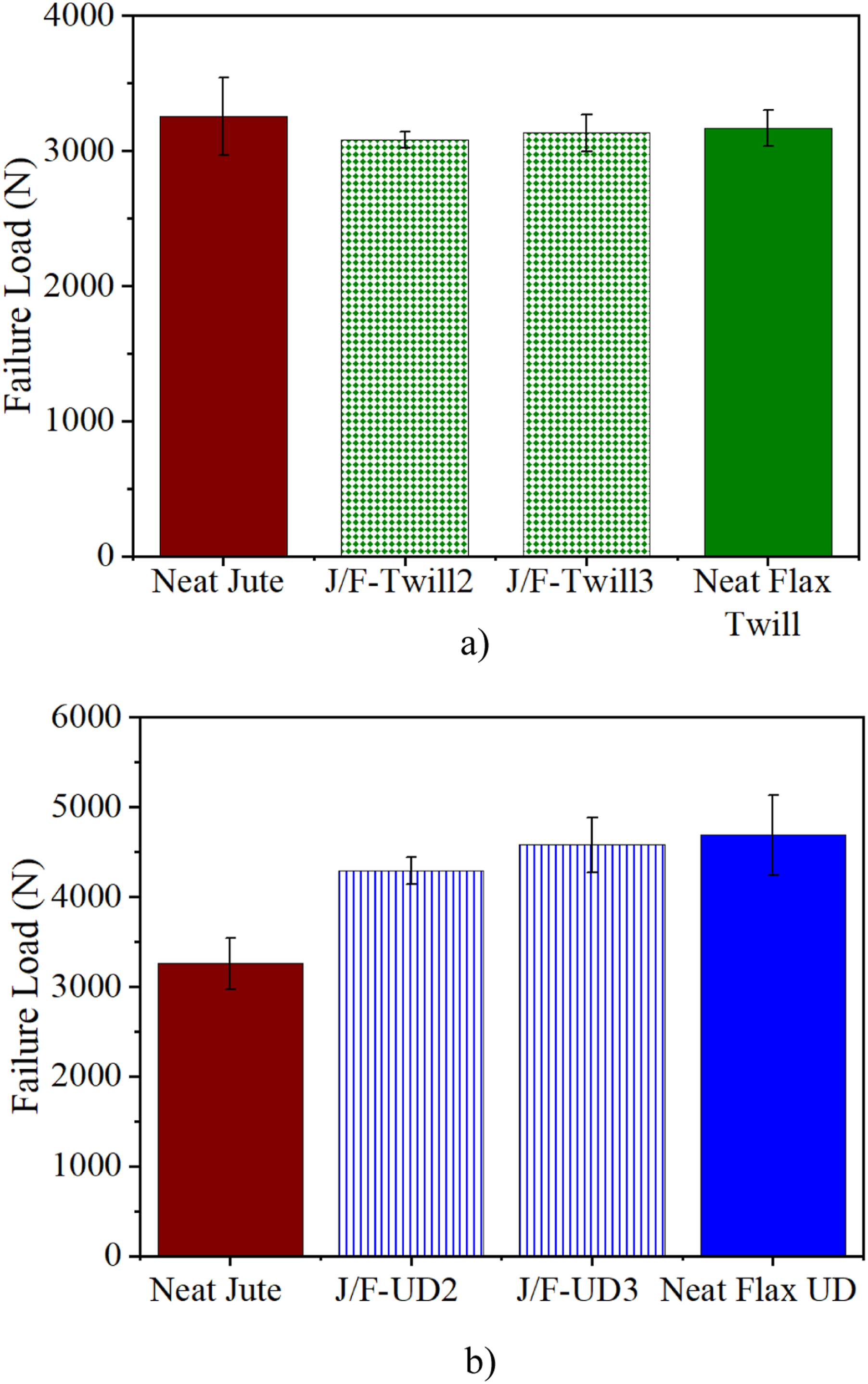
Figure 8 shows the representative load-displacement curves of the SLJs, while Figure 9 presents the quantitative statistical data. In Figure 8, it can be observed that the overall behavior of the joints was slightly ductile, with a final brittle failure. The only exception was the Neat Jute samples, due to the fragile nature of the jute composite and the rupture failure of the stock (see Figure 6(a) – failure mode). From Figure 8, it can be noted that all samples initially exhibit linear elastic behavior up to approximately 0.2 mm of displacement, after which nonlinear behavior begins to be observed. This is possibly due to plasticity and damage initiation in the adhesive layer. It is also evident that the apparent stiffness of the joint varied depending on the type of composite material used as the adherend. For example, in Figure 8(a), it is noted that the Neat Jute joint showed slightly higher apparent stiffness than the joints with adherends reinforced with flax twill (neat and hybrid). In Figure 8(b), it can be seen that the Neat Jute joint, when compared to joints with adherends reinforced with unidirectional flax, showed slightly lower stiffness than all the samples. Among the joints with neat flax composite adherends, the SLJ Neat Flax UD exhibited higher apparent stiffness compared to SLJ Neat Flax Twill. The experimental results suggest that fabric architecture significantly influences the apparent stiffness of the joint. Although the neat flax substrates show distinct mechanical properties resulting from their respective fabric architectures (Table 4), the hybrid joints exhibit a response strongly governed by the fibre arrangement at the bonding interface. The unidirectional architecture, characterized by a greater fraction of fibres aligned with the loading direction, provided a more direct load-transfer path, resulting in higher apparent stiffness compared to the twill counterparts. In contrast, the interlaced geometry of the twill fabric promotes stress redistribution effects that reduce the efficiency of load transfer through the adherend. Notably, the hybrid joints exhibited stiffness similar to their neat counterparts (i.e., comparing J/F-UD2 and J/F-UD3 with Neat Flax UD, or J/F-Twill2 and J/F-Twill3 with Neat Flax Twill), indicating that hybridization can achieve performance levels comparable to neat composites with little influence from the number of external layers. Overall, this behavior reflects the coupled influence of architecture, thickness, and fibre content on the global mechanical response of the joints. Representative load-displacement curves of all joints tested as a function of flax woven architecture: (a) Flax Twill and (b) Flax UD. Quantitative data for the SLJ tests as a function of flax woven architecture: (a) Flax Twill and (b) Flax UD.
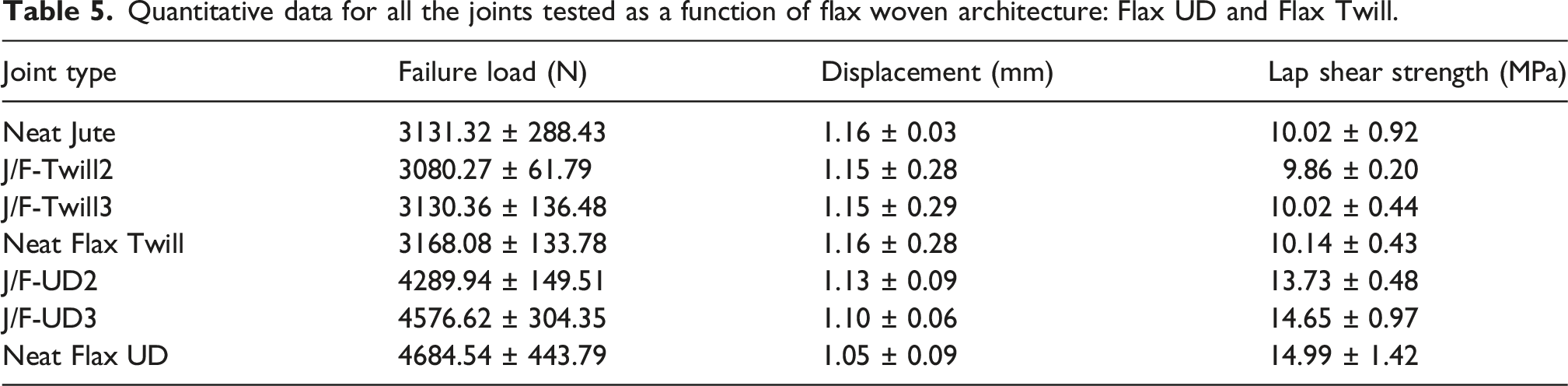
Quantitative data for all the joints tested as a function of flax woven architecture: Flax UD and Flax Twill.
In Figure 9(a), when comparing the hybrid twill flax joints with the Neat Jute joint, a plateau behavior in the average failure loads was observed, where SLJ J/F-Twill2 and J/F-Twill3 reached 3080.27 N and 3130.36 N, respectively. On the other hand, in Figure 9(b), when comparing joints with hybrid adherends reinforced with UD flax, considerable improvement can be observed. For example, SLJs J/F-UD2 and J/F-UD3 showed improvement with increases of approximately 27% and 32%, respectively.
When compared with previously reported flax-based SLJs, the present hybrid joints exhibited competitive performance. Oliveira et al. 27 reported failure loads of approximately 3284 N for Flax-Twill 250, 3892 N for Flax-Twill 400 and 2952 N for Flax-Biax configurations, whereas the present J/F-UD2 and J/F-UD3 joints reached average failure loads of 4289 N and 4577 N, respectively. While these average values are higher, the experimental scatter typical of natural fibre composites due to inherent fibre variability and processing sensitivities suggests that the results are within a similar performance range. The apparent superiority of the UD-hybrid configurations can be attributed to the higher properties of the hybrid substrates with UD flax—tensile strength and composite stiffness (see Table 4), which help minimize the rotation of the overlap edges during loading, as well as by the fabric architecture, which conditions the failure to a more controlled and less severe mode (light fibre tearing—LFT) and delays the onset of delamination failure, as observed in the previous section.
When comparing the 3-layer hybrid twill flax SLJ (J/F-Twill3) with the 2-layer one (J/F-Twill2), the difference in the average failure load was marginal (an increase of ∼1.6%), suggesting a limited benefit from the additional layer. For the 3-layer unidirectional flax hybrid SLJ (J/F-UD3) compared to the 2-layer one (J/F-UD2), a slightly higher increase of approximately 6.3% is noted, which is small when compared to the inherent variability (standard deviation) of the tests. However, the difference in failure loads becomes more evident when comparing hybrid joints with different flax fabric architectures (i.e., twill vs UD), while keeping the number of layers the same. For instance, the 2-layer twill flax hybrid SLJ (J/F-Twill2) exhibited a failure load approximately 28% lower than that of the 2-layer unidirectional flax hybrid SLJ (J/F-UD2), while the 3-layer twill flax SLJ (J/F-Twill3) had a failure load approximately 32% lower than that of the 3-layer unidirectional flax SLJ (J/F-UD3). Therefore, the flax fibre architecture is a parameter that influences the average failure load performance of hybrid SLJs, highlighting the importance of considering fabric characteristics in the design of structural composites, while the increase in the number of layers showed a limited impact under these specific conditions.
When comparing the hybrid SLJs with their respective neat joint counterparts, i.e., with Neat Flax UD and Neat Flax Twill, some similarities can be observed. For example, the hybrid joints with UD flax (J/F-UD2 and J/F-UD3) achieved 92% and 98% of the failure load of Neat Flax UD (4289.94 ± 149.51 N and 4576.62 ± 304.35 N vs 4684.54 ± 443.79 N, Table 5), demonstrating near-equivalent performance despite hybridization (<10%). Similarly, twill flax hybrids (J/F-Twill2 and J/F-Twill3) reached 97–99% of Neat Flax Twill strength (3080.27 ± 61.79 N and 3130.36 ± 136.48 N vs 3168.08 ± 133.78 N), suggesting that adding flax layers beyond two provides negligible gains (<3% difference).
To further assess the observed similarity between the hybrid and neat flax joints, a rigorous statistical validation was performed. A one-way ANOVA followed by Tukey’s post-hoc test was performed on the failure load data, considering the number of specimens per group as described in the methodology. In this analysis, a p-value <0.05 indicates that the investigated parameter (architecture or layer number) significantly affects the joint performance, while p > 0.05 suggests that any observed variations are within the expected experimental scatter. The statistical results confirmed that while the UD-hybrids (J/F-UD2 and J/F-UD3) showed a highly significant improvement over the Neat Jute baseline (p < 0.001), the differences between Neat Jute and the twill-hybrids were non-significant (p = 0.992 for J/F-Twill2 and p = 0.999 for J/F-Twill3). Furthermore, the analysis verified that increasing the number of flax layers from two to three provided no significant gains for either UD (p = 0.642) or Twill (p = 0.988) architectures. In contrast, when comparing hybrids with the same number of layers but different architectures (UD vs Twill), the differences were highly significant (p < 0.001), reinforcing that fabric geometry is the primary driver of performance. Finally, no statistically significant differences were found between the hybrid joints and their respective neat flax counterparts (p = 0.435 for J/F-UD2 vs Neat UD and p = 0.885 for J/F-Twill2 vs Neat Twill). These findings statistically validate that a hybridization strategy with only two external layers is sufficient to replicate the performance of neat flax joints, regardless of the architecture used.
The average Lap Shear Strength (LSS) was utilized to evaluate joint performance, as this normalized metric allows for a clearer observation of how the external flax fabric architecture influences the assembly, despite the inherent variations in substrate thickness and fibre content. As shown in Figure 10 and Table 5, the LSS results reveal a significant disparity between the two architectures: while UD-reinforced hybrids achieved a substantial increase in shear strength compared to the Neat Jute baseline, the twill-reinforced joints showed a performance plateau, with values nearly identical to the neat jute. This behavior suggests that the intrinsic efficiency of the joint is predominantly dictated by the fabric’s mesoscale geometry at the bonding interface rather than solely by global substrate parameters such as adherend thickness. Average lap shear strength (LSS) of the SLJs as a function of flax fabric architecture: (a) Flax Twill and (b) Flax UD.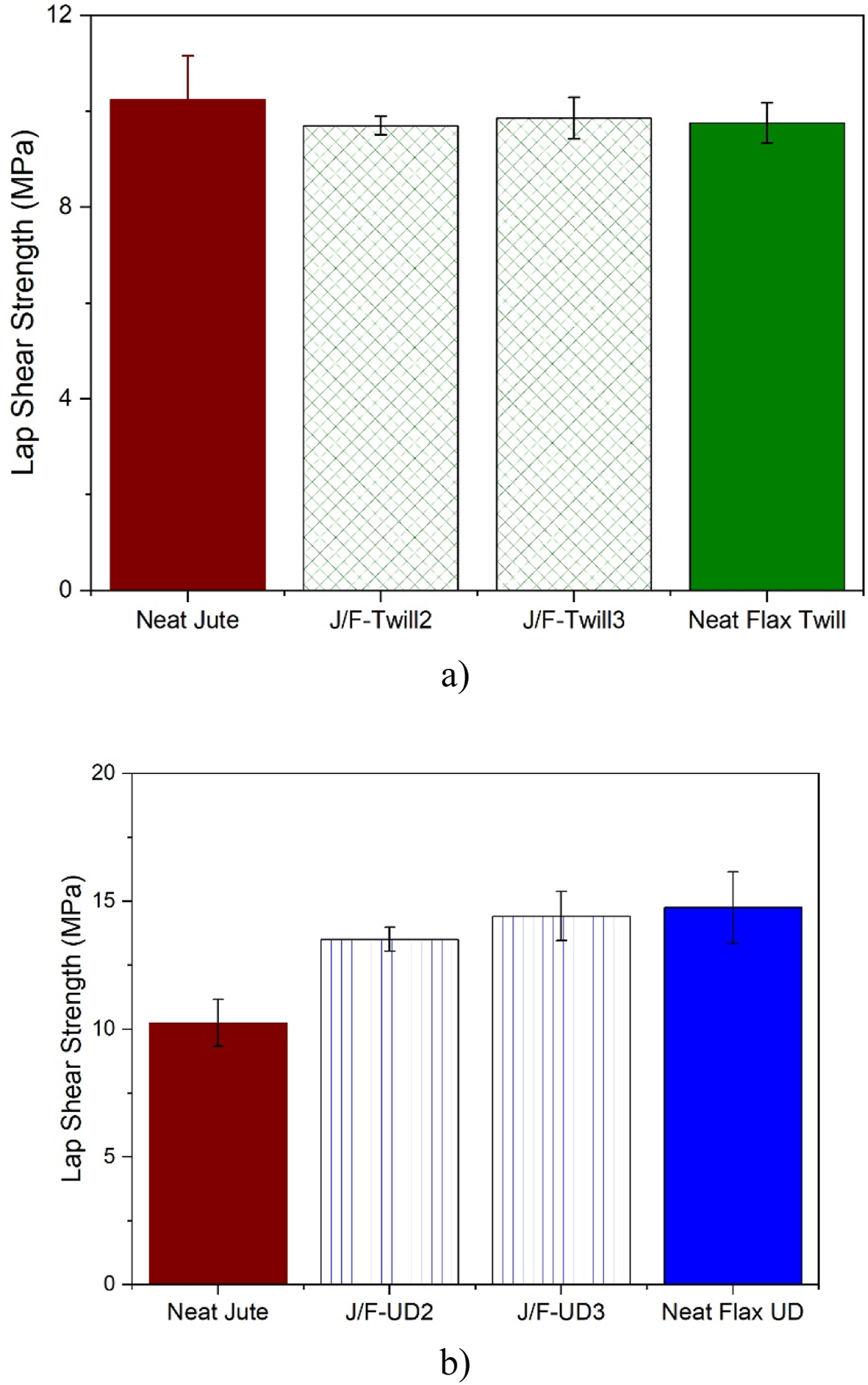
This architectural influence is directly linked to the observed failure modes (see Figure 6). In the UD flax hybrids, the alignment of the fibres at 0° promotes a more stable stress distribution that constrains the crack path to the adhesive/resin interface, leading to light fiber-tear (LFT) failure. This mechanism allows the joint to reach higher LSS values (up to 14.65 MPa) by delaying the onset of severe structural damage. In contrast, the bidirectional structure of the twill fabric facilitates crack penetration into the laminate. The interlacing of warp and weft fibres creates regions of stress concentration that promote early delamination, regardless of the additional thickness provided by extra layers. 24 Consequently, the twill hybrids exhibit a lower and more stagnant LSS (approx. 10 MPa), as the failure is governed by the premature interlaminar rupture of the twill architecture.
Therefore, the LSS highlights that, although substrate stiffness and thickness contribute to joint performance, the superior behavior of UD hybrids is predominantly associated with the more favorable failure mechanism promoted by the unidirectional architecture. Even with marginal differences in fibre content and thickness between the 2-layer and 3-layer configurations, the LSS remains primarily sensitive to the fabric type. This confirms that, for the hybrid jute/flax joints investigated in this study, the external layer architecture represents one of the most influential design parameters governing bonded joint strength and failure progression.
The observed similarity in the average failure load and LSS can be associated with the failure modes of the SLJ joints. As previously discussed, for both SLJ joint failure modes, there is a critical load at which plastic damage initiates in the adherend surface resin, causing the crack to develop, either toward the inner layers of the adherends (twill flax SLJ joints) or toward the resin/fibre and adhesive interface (UD flax SLJ joints). As observed, SLJ joints of each flax architecture type exhibited similar failure modes, demonstrating that failure always begins at the same load, remaining below the plastic damage threshold of the adherend. Therefore, even if the adherend properties are improved, this will not influence the critical load required for the initiation of plastic damage in the adherend surface resin. This explains why SLJ joints exhibited similar failure behaviors among their counterparts, with failure progressing predictably regardless of changes in adherend properties. Finally, this similarity in performance highlights the importance of considering other factors, such as material architecture and layer configuration, when selecting joint designs for specific applications.
To sum up, the experimental results demonstrate that the performance of hybrid jute/flax SLJs is governed predominantly by the external flax fabric architecture rather than by the mere increase in the number of reinforcement layers. While the addition of a third flax layer provided limited improvements, the use of unidirectional flax significantly enhanced joint efficiency by promoting more stable failure mechanisms and delaying delamination. These findings indicate that hybrid configurations with only two external flax layers can provide a favorable balance between structural performance, material usage, and cost, highlighting their potential for lightweight and sustainable bonded composite applications.
Conclusions
This study investigates the influence of fibre reinforcement type, architecture, and hybridization on the mechanical performance of adhesively bonded joints in natural fibre-reinforced composites. Composites reinforced with flax, jute, and hybrid interlaminar jute/flax fibres were fabricated using the compression molding technique and used as adherends. Single-lap joints (SLJs) were fabricated and mechanically tested for each configuration. The following conclusions can be drawn: • The load capacity of adhesively bonded joints in natural fibre-reinforced composites is strongly affected by the fibre type. Flax fibre-reinforced composite bonded joints presented higher failure loads compared to jute fibre-reinforced composites, primarily due to their different failure modes (i.e., light fibre-tear failure (LFT) for flax and stock-break failure for jute). The performance of jute and flax joints was significantly influenced by the surface morphology and mechanical properties of the reinforcement fibre fabrics, with flax exhibiting superior strength and stiffness. • The architecture of flax fibres (unidirectional vs twill) showed an important influence on the joint failure modes and load capacity. Unidirectional flax composites exhibited higher failure loads and more controlled failure modes (LFT), while twill flax composites were prone to delamination. However, the variation in failure load between different flax architectures (unidirectional and twill) was less significant compared to the influence of fibre type. • The hybridization of jute fibre-reinforced composites with flax fibres significantly improved the bonded joint performance. Hybrid joints with two layers of unidirectional flax achieved failure loads 32% higher than those with twill flax layers. This improvement is attributed to the enhanced stiffness and strength of the hybrid adherends, which reduced peel stress and minimized adherend rotation under loading, delaying the onset of delamination failure. • Hybrid joints with two layers of flax reinforcement demonstrated a viable balance between performance and cost, achieving approximately 92% of the failure load of neat unidirectional flax joints, while those with three layers achieved 98%. Similarly, hybrid joints with two layers of twill flax achieved approximately 97% of the failure load of neat twill flax joints, while those with three layers reached 99%. This suggests that hybridization can be an effective strategy for reducing material costs without significantly compromising joint strength, making it suitable for practical applications where cost-efficiency is critical.
This study provides valuable insights into the mechanical behaviour of bonded joints in natural fibre-reinforced composites, highlighting the importance of fibre type, architecture, and hybridization in optimizing joint performance. The findings offer guidance for the design and application of these materials in advanced structural applications, particularly in industries seeking sustainable and lightweight solutions without compromising mechanical integrity.
Footnotes
Funding
The authors disclosed receipt of the following financial support for the research, authorship, and/or publication of this article: This work was partially supported by the Brazilian Research Agencies: National Council for Scientific and Technological Development (CNPq)- Grant number 310268/2023-0. This work was developed within the scope of the project CICECO Aveiro Institute of Materials, UID/50011/2025 (DOI 10.54499/UID/50011/2025) & LA/P/0006/2020 (DOI 10.54499/LA/P/0006/2020), financed by national funds through the FCT/MCTES (PIDDAC).
Declaration of conflicting interests
The authors declared no potential conflicts of interest with respect to the research, authorship, and/or publication of this article.
Data Availability Statement
Data will be made available upon reasonable request.