




Abstract
In this paper, we present a method to detect anthropometric landmarks on 3D human scans automatically. Our method is a template-based approach, which builds correspondences between instance models and a template model. Spin images are used to construct the similarity measure, which represents the shape features parametrically. A vertex on the instance model will be regarded as the landmark when its similarity measure against a corresponding landmark on the template model is of maximum value. Normal variation and bounding boxes are employed to speed up the comparison of spin images. The algorithm is verified on scanned human bodies with various shapes. Forty-seven landmarks are detected on the instance body. The results show that most landmarks are found accurately. Furthermore, we demonstrate the implementation of using our detected landmarks in automatic body measurement.
With the development of 3D scanning technology, 3D surface range scanned data shows its advantage in many aspects for building more accurate digital models of a real person. 3D surface data of the human body has a lot of applications such as anthropometric studies, medical diagnosis, garment design, computer animation and entertainment. The high resolution surface data which provides accurate details of the body shape makes a remarkable change, especially in the field of anthropometry and garment design. However, the process of automatic landmark positioning on a scanned human body with various shapes is still a challenging problem. In this paper, we present a detection method to automatically extract the landmarks from the surface data by computing the corresponding information between instance models and a template model.
Previous work
Topics related to feature point detection are intended to fully benefit from 3D body scanning. Dekker et al. 1 made the exploration of feature detection operators as the first step to reconstruct the body surface. Zhong et al. 2 defined target zones to find out feature points for body segmentation. Both methods required the branching points such as armpits and crotch to be located for further treatment. The extraction of tailor measurements from a model for the lower body, consisting of two stacks of ellipses, was described by Certain et al. 3 Methods of body feature extraction in the application of MTM (made-to-measure) were also proposed by other groups.4–6 Ju et al. 7 presented an algorithm to segment the 3D human body scans by analyzing the cross-sections of the scanned body, especially the circumferences of the horizontal slices. However, the number of detected feature points was limited and less accurate. A more conventional way that computed the surface curvature in the regions of interest was introduced by Suikerbuik et al. 8 The model surface was segmented into different landmark regions based on surface curvature, by Subburaj et al., 9 and used to identify landmarks on bone models. The result was not accurate when the local surface curvature of some required features was not remarkable.
Allen et al. 10 proposed a template-based approach to fit a template human model to instances of human scans by establishing correspondences between them. All the resulting models had the same number of triangles and point-to-point correspondences. A set of anthropometric landmarks which were provided in the CAESAR (Civilian American and European Surface Anthropometry Resource) data-base 11 were pre-marked manually on the template model. After solving the correspondence problem by deforming a template model to fit individual scans, the required features were determined. This template-based approach has no limits on the number of the required landmarks. However, the manually pre-marking process, which requires 76 landmarks for each individual in the CAESAR data-base, increases the time of measurement (from a few seconds to more than 30 minutes).
Anguelov et al. 12 also proposed a template-based method to register non-rigid surfaces by using a Markov network. This algorithm was applied on 3D human scans 13 by embedding an instance mesh into a template mesh. About 200 corresponding points between the template model and instance model were selected. Therefore anthropometric landmarks of the instance model were identified when the pre-identification process was fulfilled. This algorithm was extended, by Azouz et al.14,15, to solve the location of a landmark more efficiently. A pair-wise network was regarded as an instance of a probabilistic graphical model. Each node of the model was a random variable corresponding to the position of a landmark. The edges of the network represented correlations between the positions of landmark pairs. The probability associated with alandmark encoded a preference of the local surfaceproperty around this landmark and maintained the spatial relationship between this landmark and other neighboring landmarks in the network. To characterize the local surface feature, they introduced a representative technique called spin image. 16 Spin image is traditionally used to describe the local surface feature by compressing the global 3D coordinates to2D local coordinates embedded in an image. Therefore the problem of establishing the correspondences is simplified to the problem of computing thesimilarities of a stack of 2D images. Starck et al. 17 formulated the matching problem as a bijection in the2D spherical domain to guarantee a continuous one-to-one surface correspondence without over-folding. Ghosh et al. 18 used an ICP-like framework to detect feature correspondences iteratively by using spin image to match a template with a collection of possible target meshes.
In this paper, we propose a method to detect an unlimited number of anthropometric landmarks on a scanned human body. The algorithm we applied is based on template fitting. Illuminated by the work of Ghosh et al., 18 we use spin image and Euclidian distance to establish correspondences for automatic landmark detection. However, different from their whole mesh registration, our method focuses on a simpler and more effective way to detect landmarks automatically. We also use these detected landmarks to achieve more subsequent implementations such asbody segmentation and skeleton extraction for body measurement.
Computing spin images
We formulate the problem of detecting corresponding landmarks as the problem of finding the best matches to those identified landmarks on a template mesh withsimilar shape features. In another word, it is the similarity of the feature that characterizes the local surface properties and the spatial relationship of the landmarks. In the following section we explain how the similarity is computed.
Spin images
We use spin images to characterize the feature of local surface. The concept of a spin image was first introduced by Johnson
16
who used it to solve the surface matching problem. A spin image is a two-dimensional histogram computed at an oriented point of a surface mesh. Two cylindrical coordinates can be defined with respect to the 3D position and the surface normal of the oriented point. The dense points cloud on the mesh is projected on this 2D image. By accumulating 2D points in discrete bins, spin images are generated. Darker pixels in the image indicate those particular bins contain more projected points. Figure 1 shows the coordinate system used to compute the spin image at an oriented point. The radial coordinate, α, is defined as the perpendicular distance to the line through the surface normal, and the elevation coordinate, β, is defined as the signed perpendicular distance to the target plane defined by vertex normal and its position.
Cylindrical coordinates system.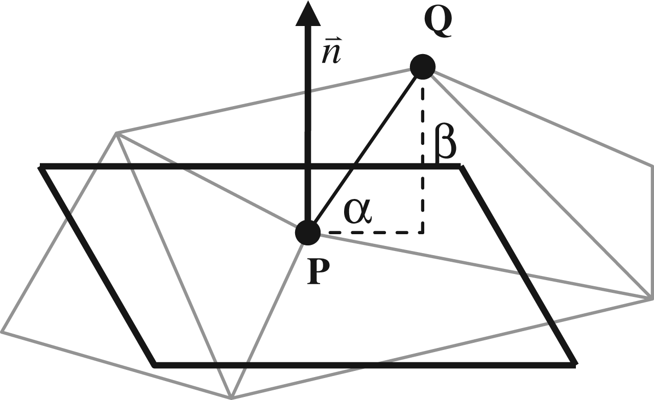
As a representation of shape feature, spin image is generated in an object-centered coordinate system, which means the description of the surface is view-independent. Hence the surfaces can be directly compared without pre-alignment. In practice, the 3D positions of vertices in the mesh are mapped into 2D using the spin map for each oriented point basis. By accumulating 2D points in discrete bins, spin image with appropriate bin size can be generated accordingly. Here, ‘bin size’ refers to the number of bins contained in each image. It is determined according to the mesh resolution of the body scan.
16
As shown in Figure 2, to facilitate our explanation, the generated spin image has 30 × 30 bin size per image. Projecting the dense points cloud to limited bins of 2D images actually compresses the abundant surface data. This will facilitate the computation when comparing the similarity. Furthermore, it can reduce the effect of poor surface data on the mesh such as clutter (extra data) and occlusion (missing data).
Spin images for an oriented point on the surface of a human model. Left to right: a) An oriented vertex of the human model; b) The 2D points map in terms of the base vertex; c) The 2D spin image.
Figure 3 shows examples of spin images generated on two different human scans. For each scan we choose five landmarks for instance. Notice that the spin images corresponding to the same landmark from different human scans are intrinsically similar with each other.
Spin images computed for five landmarks on two different human scans.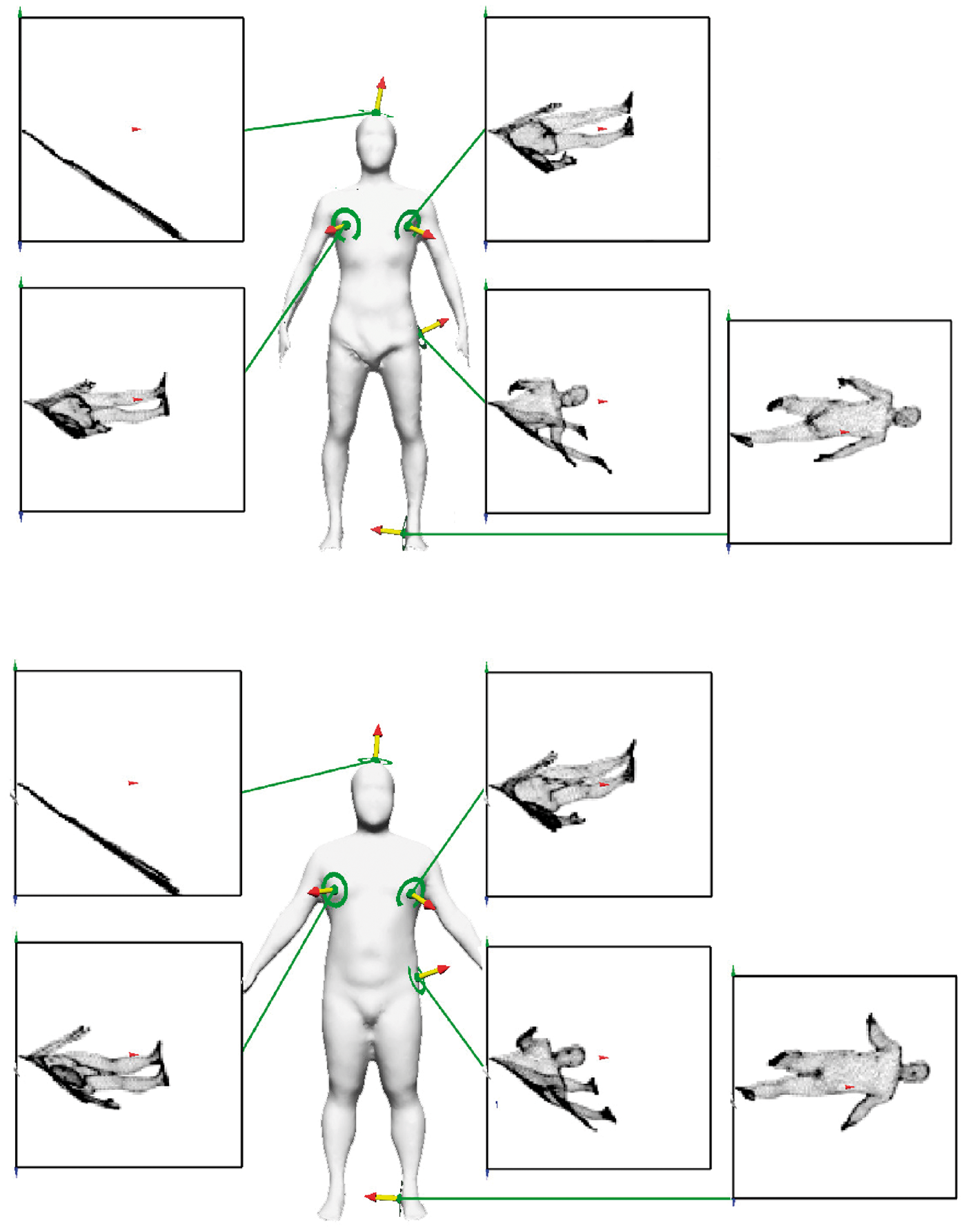
Matching algorithm
To set up the landmark correspondence between instance model and template model, the matched pair should have the similar shape feature and spatial position. With these two criteria, we formulate the similarity measure, S, as:

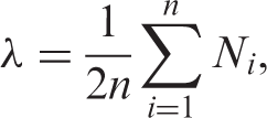
In equation 1, the first part measures the similarity of the surface feature. The ranged space of weight, β, is valued between 0 and 1. The second part calculates if the selected point is close enough to the corresponding landmark, where d stands for the Euclidean distance. The selection of β depends on the distinctiveness of the local surface feature, which will be discussed in detail later. C indicates the similarity of the generated spin images. It combines the linear correlation coefficient R and its variance affected by the amount of overlapped pixels between spin images:
19

Pre-marking
We choose a normal size, hole-free male body as our template mesh for the explanation. The posture of the subject before whole body scanning is demanded as standing with arms spread slightly apart from torso, as illustrated in Figure 3. In this paper, 29 landmarks that provide the most useful anthropometric data forthe clothing related applications are selected. To reduce the objective error in the collection of anthropometric data, we use the unified description of the definition introduced by Simmons et al.
20
Furthermore, we pick four extra landmarks from the template model to assist the automatic detection. They are points on fingertips and heels. As shown in Figure 4, the red spheres are the main landmarks and the blue spheres are the assistant feature points. The anthropometric nomenclature of these landmarks is given in Table 1.
Positions of 29 pre-defined anthropometric landmarks. The anthropometric nomenclature of landmarks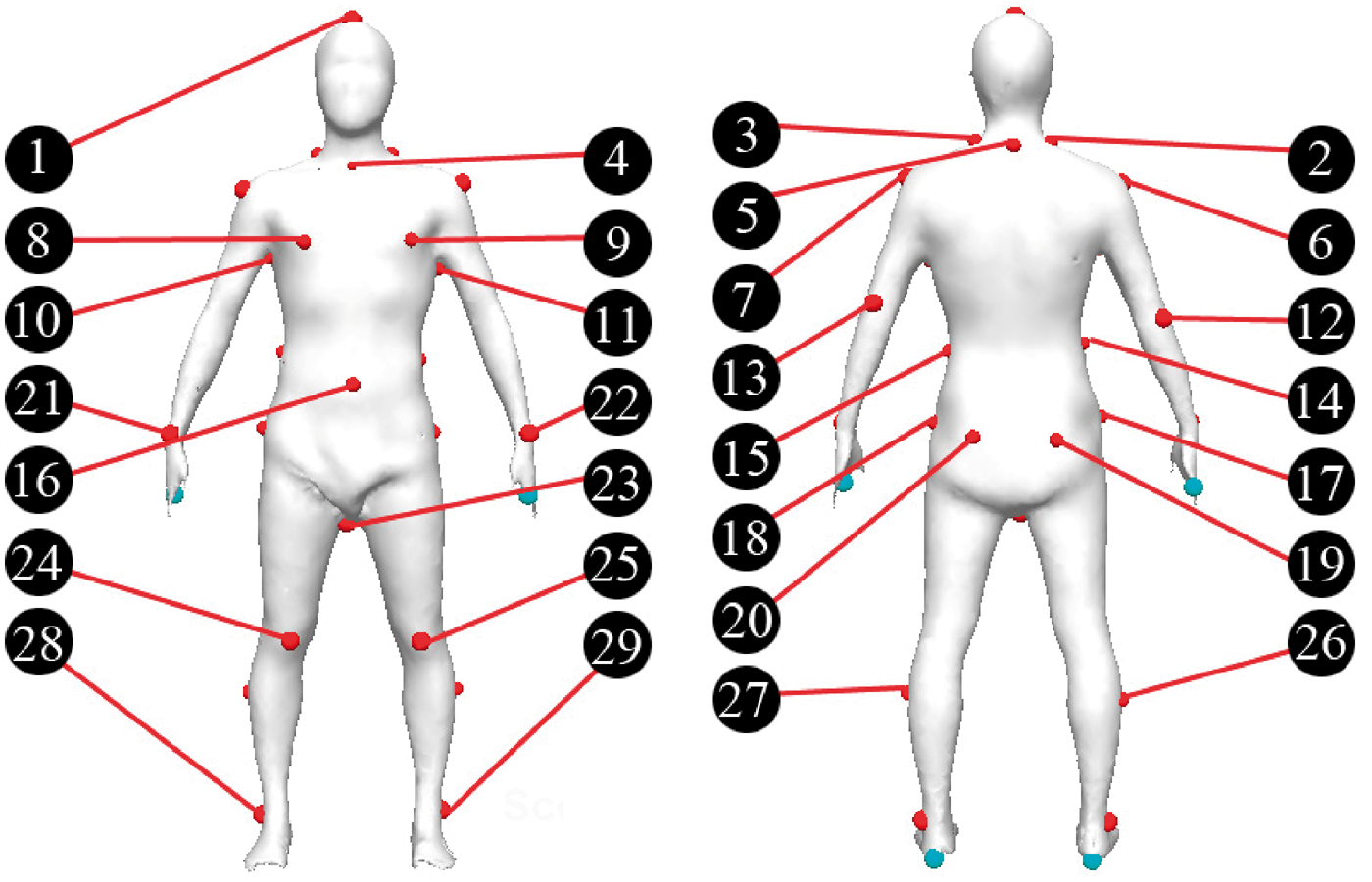

After manual pre-marking, spin images with proper parameters generated from these points are stored for future comparison. The optimal selection of parameters for spin images is determined by the average length of the mesh edges. 16 In practice, the resolution of the models is around 7000–8000 points. We find that choosing 100 × 100 bin size to generate spin images seems to be appropriate in shape comparison.
Detecting landmarks
Since spin images are generated according to the oriented points, the features of the landmarks can be categorized by the variation of the surface normal. In this sense, 29 landmarks on the surface of a template scan are divided into three types that represent different shape characteristics.
Geometrically, most of the landmarks have a palpable geometric feature and vary only in size and spatial location. These anatomical landmarks on each single body segment are usually constrained by a spatial relationship that is the same for each model. We therefore propose an additional characteristic for narrowing thescope of landmark identification: invariable relative position of a landmark with respect to other known landmark. This can be achieved via bounding boxes built according to the key landmarks.
Extraction of landmark regions
The equation we apply to evaluate the variation of the surface normal is defined as:

After computing the variation of the surface normal for each vertex on the template scan, three viewpoint-independent surface types can be formed accordingly. Different types refer to a different valueof β in computing the similarity measure S when we match the corresponding landmarks between the template model and the instance model. Figure 5 illustrates the normal variation on each vertex mapped with color values on the template surface. The definition of three types of surface, the categories of 29 landmarks and the selection of weight β in equation 1 are given in Table 2.
Variation map of surface normal on the template scan. Different landmark types based on the variation of surface normal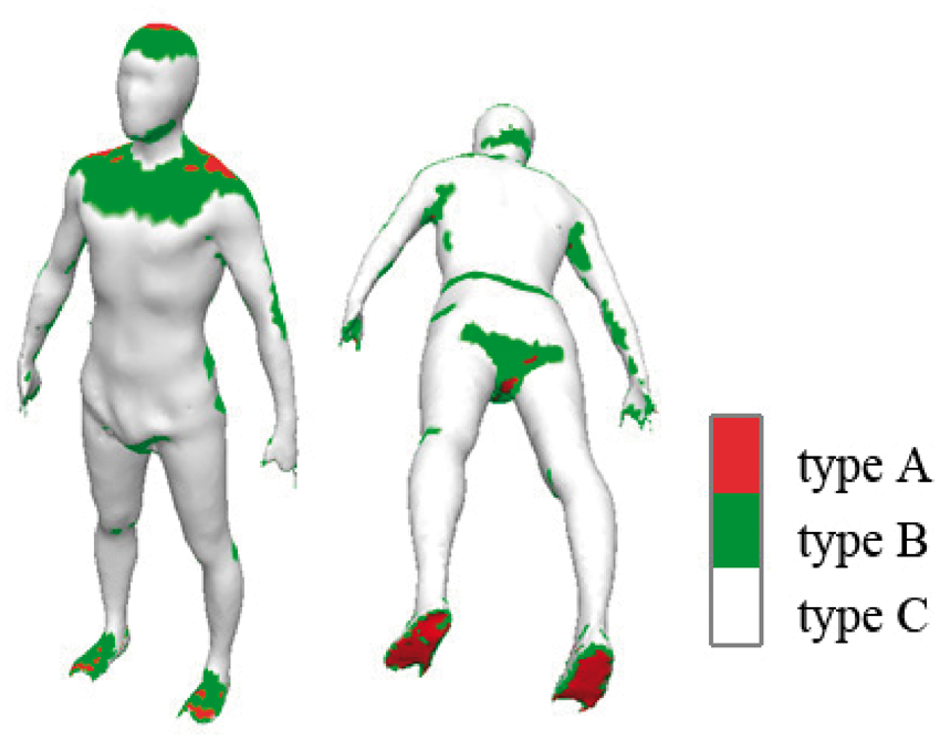

The categorized normal variation implies that thelandmarks on the template model will fall into the same types of landmark region on the instance model. This actually builds the regional correspondence between two models. The searching of landmarks on the instance model will then be carried on the same type of region.
Detecting key landmarks
The key landmarks which are classified into type A areoriented points on the body surface with uniqueness in shape characteristics in their vicinity. From our observation, the key landmarks can always be detected precisely. Hence they are detected on the instance scans primarily.
The similarity measure S in equation 1 gives us a way of evaluating spin images. Two spin images with the highest similarity measure are likely to come from two vertices with the same surface feature. In the detecting process, the instance model is calibrated to the same height as the template model, and then it is restored with the same calibration parameters in a reverse manner after landmark detection. For a known landmark on the template model, the spin image will be compared with the spin images extracted from the same type of landmark region on the instance model. The detailed steps follow:
Select a key landmark qi from the template model, and load its spin image Ω
qi
; For type A vertex pj from the instance model, if the Euclidean distance d between qi and pj is less than 20 cm, and the angle between oriented vertex qi and pj is less than 90°, load its spin image Ω
pj
; Use equation 1 to compute the similarity measure S; The type A vertex from the instance model with maximum S will be regarded as the matched key landmarks.
In practice, eight key landmarks can be easily extracted with these four steps of treatment, as shown in Figure 6 (the red spheres).
Five bounding boxes based on the detected key landmarks.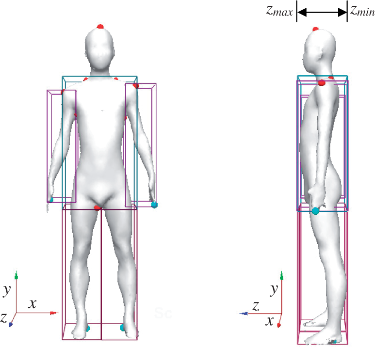
Bounding boxes
After detecting the key landmarks, we use them to build bounding boxes for further landmark detection. The bounding boxes are defined in terms of the body parts, i.e., torso, left leg, right leg, left arm and right arm respectively. Technically, they are employed to calculate a more accurate relative position when we compute with the similarity measure.
Bounding boxes based on corresponding landmarks
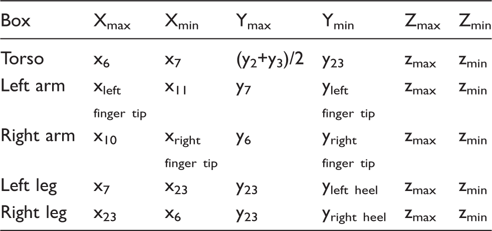
To facilitate our explanation, we use the right arm as an example, as shown in Figure 7. The bounding box for the right arm is built based on three key landmarks, i.e., right finger tip, right acromion and right armpit. Inthe detecting process, the position of the landmark p on the template model can be mapped onto the instance model at the position p″ by maintaining the same coordinates in the bounding boxes of the template and instance model:
Using the bounding box of the right arm to detect the landmark on the right wrist.



Although p″may or may not be a vertex on the instance model, we always use it as the benchmark for similarity comparison. In this sense, the spin image stored for landmark p should also be transferred to point p″. Now let pi be the candidate vertex on the instance model, the searching is still limited in the region where the Euclidean distance d between pi and p″ is less than 20 cm, and the angle between oriented vertex pi and p″ is less than 90°. By comparing the similarity measure S, we can detect all the landmarks that are classified into type B and C in Table 2.
Experimental results and discussions
We applied our algorithm to over 200 human scans including both male (117) and female (112) subjects in a wide variety of human body shapes. Figure 8 and Figure 9 illustrates the girth values and height value of the subjects measured in terms of the landmarks detected by our proposed method. Obviously, the measures of these body shapes are quite different. This means our proposed method can satisfy a wide variation of body shapes.
Shape differences among female subjects. Shape differences among male subjects.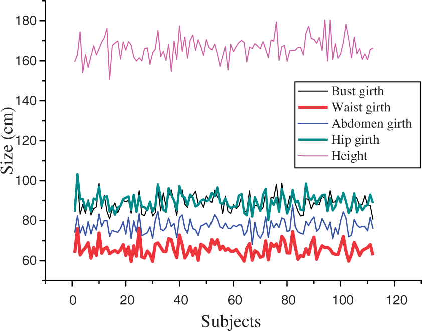

To demonstrate the result of our proposed method, several typical body shapes including obese shape (fromleft to right, the 5th male body in the first tworows of Figure 10) are illustrated, as shown in Figure 10.
Examples of our experiment with 47 detected landmarks on each scan. The first model at each row is the template model for landmark detection, in front view and back view respectively.
The 29 landmarks are represented as red spheres, and there are 18 extra landmarks represented as blue spheres. For these extra landmarks, four of them are the aforementioned extra key landmarks to define the end of each branch (left fingertip, right fingertip, left heel and right heel). The other 14 extra landmarks are employed for precise body segmentation (Figure 11) in automatic body measurement. Technically, it is wise to segment the human body into torso and limbs prior to circumference and/or distance measurement. This makes the automatic body measurement easier and more accurate than taking the whole body as the subject, since each segmented branch is a cylinder-like object. For instance, if we want to measure the waist girth, a cutting plane passing through the most concave position on torso will not take the left and right arm into account. Figure 11 demonstrates the automatic body segmentation and measurement based on the landmarks detected by our proposed method. The skeleton for the instance model can also be extracted by setting the joints as the center of the concerned girth. The detailed algorithm of body measurement and skeleton extraction can also be found in our previous investigation.
2
Automatic body segmentation and measurement.
In computer animation, the skeleton is usually employed as the benchmark to drive the skin in various motions, usually equipped with the motion captured data. In this type of application, the pre-marked landmarks for a motion captured subject (template) can beeasily transferred onto an instance model. Hence themotion can be transferred accordingly, and can beemployed in 3D virtual dressing system to provide more realistic visual effects in animation such as runwaywalk.
The Euclidean distances between the predicted landmark positions and their corresponding position placed manually according to their anthropometry definitions are calculated to verify the accuracy of our algorithm. Figure 12 shows the average error for each landmark.
Average errors of 29 auto-detected landmarks against manually pointed landmarks.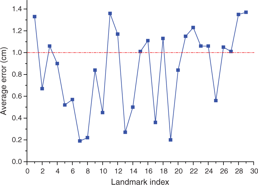
Obviously, for all of the 29 landmarks, the maximum error is less than 1.4 cm, which coincides with the human experience when performing the landmarking and measurement manually. 21
Aside from anthropometric landmark positioning, our proposed method can be employed in a more flexible manner in determining the customized landmarks. For instance, in 3D bra design or comfort evaluation, it is important to locate the breast area on the 3D human body. Figure 13 illustrates examples of breast zone detected for different female body shapes. 19 landmarks around the target area were pre-defined on the first template model.
Results of breast zone detection for female scans based on our algorithm. Left to right: (a) template model with 19 customized landmarks; (b, c, d) automatically detected landmarks on different female scans.
To evaluate the performance of our proposed method, we implemented our algorithm on a PC with Core Dual CPUs at 2.8 GHz, and 1 GB Memory. The running time for the detection of all 47 landmarks (including the extra landmarks used for skeleton extraction and body segmentation) on an instance scan is usually under one half minute. The scans we picked have around 7000–8000 points. We also apply our algorithm for detecting scans with different mesh resolution. Results demonstrate that the time spent per-landmark depends on the number of points we searched in the region of interest. It can be controlled by using different searching parameters such as searching radius and permissible variation of normal. Since the dimension of spin images (bin size) is set to approximately the mesh resolution,
16
landmarks detection using spin images is sensitive to mesh quality. We find that the higher the density of points, the higher the accuracy of the result and the higher the running time of the algorithm. The running times for the detection of all 47 landmarks on scans with different mesh resolution are shown in Figure 14.
Running times for detection runs on scans with different mesh resolution.
Although most of the landmarks can be detected accurately, the landmarks located on non-significant regions may have less accuracy such as the navel (thefourth scan in the first row in Figure 10). Such inaccuracy of detection is caused by the fact that those landmarks are not clearly identifiable points with surface feature descriptor and it might be caused by poor surface reconstruction in body scanning. Another observed limitation is that once the pre-marked landmark offsets from its anthropometric position, the detected landmark on the instance model cannot overcome this historic error, which commonly exists in template-based approaches.
Conclusion
In this paper, we present a method for automatically detecting anthropometric landmarks on 3D scanned models. To describe the local surface feature, spinimages at each oriented point are adopted. Thelandmark detection is performed by comparing the similarity measure defined upon the spin images between known landmarks on the template model and the candidate vertex on the instance model. Normal variation and bounding boxes are employed to speed up the comparison. Experiment results show accurate landmark detection can be achieved in a short time by using our proposed method. In addition, the body segmentation and skeleton extraction as two common applications can be easily carried by using these detected landmarks.
Footnotes
Funding
This work was supported by the Natural Science Foundation of China (grant number 60973072) and the Fundamental Research Funds for the Central Universities (grant number 2011D10102).