



Abstract
Knitted spacer fabrics have been developed into a variety of special textile products for a wide range of applications. As a type of sandwich structure, their applications are largely dependent on their compression properties. Although several experimental and theoretical studies have been carried out on their plate compression properties, their spherical compression behaviors have not been deeply studied yet. This paper reports a study of the spherical compression behavior of knitted spacer fabrics. The paper includes two parts. The first part focuses on a theoretical analysis of a spacer fabric under spherical ball compression. A theoretical model is developed to predict the spherical ball compression properties of the fabric. The non-dimensional parameters are introduced to analyze the effects of the fabric thickness and ball radius based on the theoretical relationship established between the compression force and compression strain at the maximal compression point. The analysis results reveal that the spherical compression effects decrease with increasing ball radius, and increase with increasing the fabric thickness. It is expected that this study could help us better understand the behavior of knitted spacer fabrics under spherical compression.
Introduction
Spacer fabrics have been developed into a variety of special textile products by varying their structure design and finishing methods for a wide range of applications, such as sound absorption, 1 – 3 moisture transport, 4 functional bra support, 5 comfort property enhancement, 6 car seats 7 and composite reinforcement. 8 As a kind of the sandwich structure, the applications of spacer fabrics are largely dependent on their compression properties. In the case of apparel use, the compression properties of spacer fabrics should be soft to handle and they should be able to fit the shape of the body. Constructed with two separate knitted fabrics as the upper and bottom layers and flexible filaments as the inner layer, both weft and warp-knitted spacer fabrics can be designed as a kind of soft spacer fabric structure to meet the need of special applications such as bra cups 5 and flexible cushioning or padding materials. 9 Experimental investigations of physical and compression properties under low stress have been carried out for different knitted spacer fabrics used for intimate apparel.10,11 Other studies have also demonstrated that the knitted spacer fabrics have better pressure distribution, air permeability and heat resistance than those of polyurethane foams.7,9 In particular, knitted spacer fabrics can be used as pressure release products such as functional mattresses and wheelchairs for reducing peak pressure to avoid the concentration of pressure on the body.7,9
In order to effectively evaluate the applications of the knitted spacer fabrics in different shapes of the body, it is important to understand their compression properties under spherical compression conditions. Although several experimental and theoretical investigations on the compression properties of knitted spacer fabrics have been carried out,9,12– 19 these investigations have only focused on the compression behavior under plane compression conditions. Only one paper, published in Chinese, reported a study of the spherical compression behavior of warp-knitted spacer fabrics. 20 In this paper, the spherical compression tests of various warp-knitted fabrics were conducted and the compression stresses at the maximal compression point of the spherical ball for different compression strains were calculated based on the Hertz theory developed for elastic homogeneous materials under small strain conditions. 21 Although a finite element simulation was also included in this paper, analytical models for predicting the spherical compression behavior of knitted spacer fabrics are still lacked.
The present paper reports a study of the spherical compression behavior of knitted spacer fabrics. The paper includes two parts. In the first part, the study focuses on a theoretical analysis of a spacer fabric under spherical ball compression. A theoretical model to predict the spherical ball compression properties of the fabric is set-up based on the compression constants derived from its plane compression stress-strain curve. The non-dimensional parameters are also used to discuss the effects of the fabric thickness and ball radius based on the theoretical relationship established between the compression force and compression strain at the maximal compression point. It is expected that this study could help us better understand the behaviors of knitted spacer fabrics under spherical compression.
Model derivation
Description of compression methods
In order to make the basic assumptions for a theoretical model, it is necessary first to give a brief description of compression methods. Both the plane plate compression and the spherical ball compression on a knitted spacer fabric are schematically shown in Figure 1a and 1b, respectively. Two compression methods can be switched by just changing the corresponding compression assemblies. While for the plane compression test the spacer fabric is compressed between two plane plates (one fixed and the other moved) as shown in Figure 1a, the spherical compression test is carried out by moving a spherical ball to compress the knitted spacer fabric which is placed on the fixed platform, as shown in Figure 1b. In order to avoid the possible movement of the specimen during the compression test, it is suggested that the bottom side of the specimen should be secured to the platform using double-side considerably adhesive tape.
Schematic presentation of compression testing methods: (a) Plane plate compression; (b) Spherical ball compression.
To have a theoretical analysis of the spherical compression behavior of the knitted spacer fabric, the contacting shape of the knitted spacer fabric with the spherical ball surface is important and should be determined first by experiment. For the isotropic material, the contacting shape must be circular because the material has the same property in all directions. However, for the spacer fabrics, the situation could be different due to their anisotropic behavior. In order to obtain the contacting shape of the knitted spacer fabric with the spherical ball surface, a preliminary test was conducted. As shown in Figure 2, the contacting shape of the fabric at a given displacement of the spherical ball was obtained by coating powder on the knitted spacer fabric face. It can be found that the contacting contour is almost circular.
Contacting shape of spacer fabric.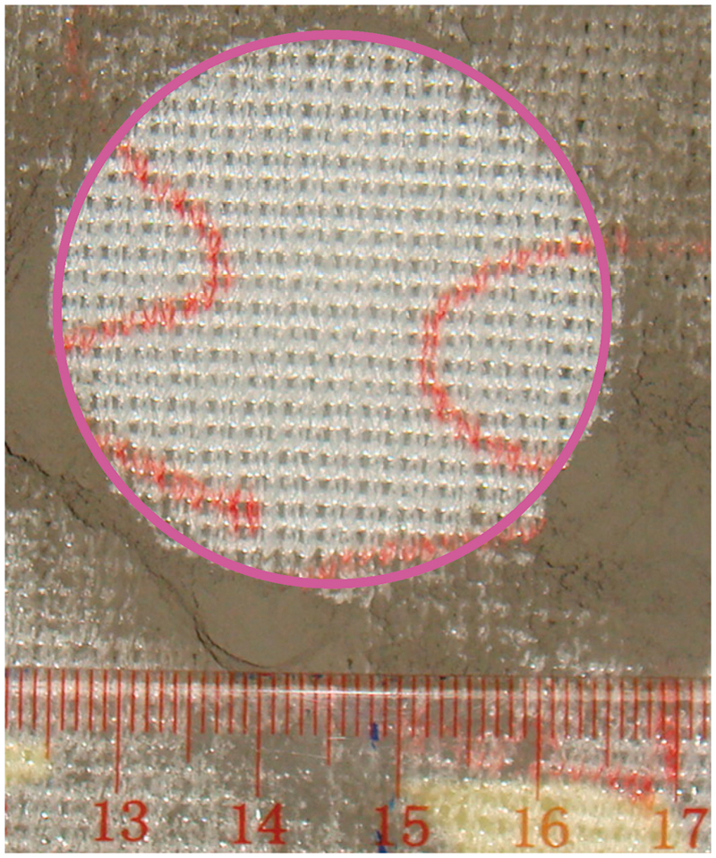
Basic assumptions
Based on the fabric shape change observed during the preliminary test, the following assumptions are made for the theoretical analysis of the spacer fabric under spherical compression:
The compression force applied by the spherical ball is mainly withstood by the spacer filament yarns. The spacer yarns do not change their vertical position along the compression direction during the compression test. This assumption is based on the fact that no obvious movement of the specimen was observed during the spherical compression test due to fixation of the bottom side of the specimen to the platform, and that the vertical direction of two ends of spacer filaments in the inner layer did not change. Thus, the component forces of spacer filaments in the horizontal direction in the inner layer could be neglected. The spacer filaments in the inner layer are assumed as spring-like elements under compression. They are deformed between the upper and bottom layers by applying the compression forces on their two ends. It is normal that under compression, the deformations of a spacer filament include axial compression, bending and torsion. All these deformations provide a resultant effect to support compression deformation of the fabric. In order to avoid the complicated analysis of a single spacer filament under compression, the plane compression behavior of spacer fabric will be used to derive the compression behavior of the idealized spacer yarns in this study. This can simplify the analysis. The idealized spring-like filaments can be linear or non-linear dependent on the fabric plane compression properties. As shown in Figure 3, the upper layer of the fabric can be split in two areas under the spherical compression, i.e., the area in contact with the ball surface and the area with no contact to the ball surface. The contour of the contacting area is assumed to be a circular form, and the expanding curve of both BA and B’A’ in the non-contacting area is assumed to have a shape of an exponential function whose asymptotic line EE’ is through the upper surface of the knitted fabric. Besides, the expanding curve has the same slope of the circular contacting curve BCB’ at the separating point B or B’ between the knitted fabric and spherical ball. The total compression force, F1, applied by the ball to the fabric equals the sum of the resultant forces withstood by both the spacer yarns in the contacting area, F2, and non-contacting area along the compression direction, F3. It is necessary to point out that the effect of F3 is transferred to the spherical ball through the deformation tension of the upper layer of the fabric in the non-contacting area. Spherical ball compression: (a) Cross-section view; (b) Projection view.

Geometrical analysis
Referring to Figure 3, the following symbols are used for the analysis: H1 – the fabric thickness; H2 – the displacement of the ball; R0 – the radius of the ball; r0 – the radius of the ball at the separating point; ϕ0 – the angle formed between the central line OO’ and BO at the separating point.
Referring to Figure 3 and using Assumption 3, the shapes of the upper layer on the cross-section in both the contacting and expanding areas can be determined. For the contacting area, the fabric is contacted with the surface of the ball, so its shape is a spherical form. Let the vertical direction line passing through the spherical center point O be known as line OO’, and the contacting area between the knitted spacer fabric and spherical ball surface is a spherical surface BCB’, where points B and B’ are the separating points. The contacting contour on plane BB’ is a circle perpendicular to the line OO’. Take any point D on arc BCB’ at which an angle ϕ between line OD and line OO’ is made, the radius r can be expressed as:

By differentiating the above equation with respect to ϕ, it yields:

The non-contacting area, which is referred to as the expanding area in this paper, is more complicated than the contacting area. It starts from points B and B’, and ends at point E and E’ located on the upper surface of the knitted spacer fabric, which is considered as the asymptotic line. In order to facilitate the calculation afterwards, points A and A’, which are very close to the upper surface of the fabric, are chosen as the limit points, and the horizontal distance l0 from point B’ to point A’ (or point B to point A) is defined as the expanding span width. In order to derive the function of the expanding curve starting from B’ (the curve from B is the mirror image), a cartesian coordinate system of XB’Y is established by setting horizontal line B’X as the x-axis and vertical line B’Y as the y-axis. Based on Assumption 3, the following exponential function is proposed to be a curve function of arc B’A’ whose asymptotic line is set as line EE’:

Equation 2 should meet two boundary conditions. One condition is to have the same slope as the circular BCB’ at the separating point B’, that is,

The other condition is that the vertical distance from point B’ to the upper surface line EE’ (Ymax) should be

Using equation 4, equation 2 becomes:

By differentiating equation 5 with respect to x and using equation 3, the following equation is obtained:

Equation 6 determines the position of the separating points B and B’. To obtain the value of ϕ0, equation 6 can be modified to the following form:

Since the compression displacement H2 is smaller than the diameter of the spherical ball, 2R0−H2 cannot be zero. So, equation 7 is a quartic equation with one unknown. Although four roots can be obtained from this equation, the only root, where angle ϕ0 is between 0 and π/2, can satisfy it, as shown in equation 8.


The detail of solving equation 7 to obtain ϕ0 is shown in the Appendix.
During the spherical compression test, it was observed that the expanding zone span width l0 in the expanding area under compression deformation did not exceed the border of the knitted spacer fabric sample. From this observation, it is possible to set a value for l0 under conditions such that the vertical distance from the separating point B’ to point A’ (YA’) is very close to Ymax, that is,


In this analysis, h was selected as 0.99995, which corresponds to a compression strain level less than 0.005% from point A or A’ to the border of the knitted spacer fabric. At this deformation level, the resultant force withstood by the spacer filaments in the expanding area EA and E’A’ is less than 0.05% of the resultant force withstood by the spacer yarns in the expanding area EB and E’B’. In such a consideration, only the compression force in the expanding area from points B/B’ to A/A’ is considered. The effect from points A/A’ to the border of the fabric can be neglected as the effect is very small.
Take any point P in the expanding area B’A’, the horizontal distance r’ from axis OO’ to point P is given as follows:

Compression force analysis
According to Assumption 4, the total compression force F1 applied by the spherical ball on the fabric equals the sum of the resultant forces withstood by the spacer filament yarns in both the contacting area and non-contacting area along the compression direction. In other words, the total compression force F1 can be expressed as

It is necessary to point out that F2 and F3 correlate with the compression strain ε of the knitted spacer fabric, where ε is varied along the upper layer of the fabric for a given displacement of the compression ball. Suppose that the reaction force per unit area on the bottom surface of the fabric is f(ε), F2 and F3 can be separately calculated as follows.
As shown in Figure 3, first select an annular element of dr at point D in the contacting area BCB’, where the angle between the normal line OD and central vertical line OO’ is ϕ, and the radius of the annular is r. Then the compression strain ε at this point is given by

Using equation (1), the reaction force on the bottom surface of the annular element in the vertical direction can be expressed as:

Thus, F2 can be obtained by integrating equation (14) from 0 to ϕ0, where ϕ0 is determined by equation (8),

The same method can be used to calculate F3. Take an annular element of dx within the expanding area where the shape of curve B’A’ is determined by equation (5). From equation (5), the compression strain ε at any point P in the B’XY system is obtained as follows:

Using equation (11), the reaction force on the bottom surface of the annular element dx in the vertical direction can be expressed as:

Thus, F3 can be calculated by integrating equation (17) from 0 to l0, where l0 is determined by equation (10),

The above analysis shows that the calculations of F2 and F3 need to know the reaction force per unit area on the bottom surface of the fabric f(ε). Based on Assumptions (1) and (2), f(ε) can be calculated from the plane compression testing results for the same compression strain ε. The plane compression of a knitted spacer fabric is schematically presented in Figure 4, where a plane specimen with a thickness H1 and a surface A is compressed to a displacement H2.
Plane compression of knitted spacer fabric.
The previous studies have shown that the compression curve of knitted spacer fabric under plane compression can be split into different regions.18,19 A typical compression curve of a warp-knitted spacer fabric is shown in Figure 5. It can be found that the whole curve can be split into three regions and the curve segment in each region can be approximately represented by a linear relationship between the compression stress and strain. In this regard, f(ε) is assumed to have the following relationship with compression strain ε:
A typical compression curve of a spacer fabric.

When f(ε) is known, F2 and F3 can be finally calculated. Substituting equations (13) and (19) into equation (15) and after integration, the following equation for calculating F2 is obtained:

Substituting equations (16) and (19) into equation (18) and after integration, the following equation for calculating F3 is obtained:

Model discussion
In order to better understand the spherical compression behavior, the following non-dimensional parameters are introduced:

Here H' is the compression strain at the maximal compression point C. According to equation (10), when the value of coefficient h is chosen as 0.99995, the value of l0 is larger than 10. So, both 

Thus, the compression force F1 can be expressed in non-dimensional form 
From equation (25), it is found that F1' depends on the spherical ball radius R0 and the fabric thickness H1. The variations of F1' against H' for different R0 when H1 is kept unchanged (H1 = 18 mm) are shown in Figure 6. It can be seen that F1' decreases with increasing the ball radius R0. This means that the effect of the ball radius decreases with increasing the ball radius. This is normal because when increasing the ball radius, the spherical compression will be closer to the plane compression. In fact, the plane compression can be considered as a special case when R0 trends to infinite.
variations of 
The variations of F1' against H' for different H1 when R0 is kept unchanged (R0 = 50 mm) are shown in Figure 7. It can be seen that F1' increases with increasing fabric thickness H1. This means that the compression effect increases with thicker fabrics. This is normal because by increasing the fabric thickness, the ball contacting the surface with the fabric increases, which leads to a greater effect under the spherical compression.
variations of 
Conclusions
A theoretical analysis of the spherical compression behavior of knitted spacer fabrics is conducted based on the basic assumptions made from a preliminary test. The shape of the fabrics deformed under the ball compression is analyzed and the relationship between the total compression force applied by the spherical ball, and compression strain at the maximal compression point, are established. The effects of both ball radius and fabric thickness are discussed based on the introduction of non-dimensional parameters. The analysis results show that the spherical compression effects decrease with increasing the ball radius, and increase with increasing the fabric thickness. The analysis of the experimental results and their comparison with theoretical calculations will be presented in Part II.
Footnotes
Funding
This work was supported by the Innovation and Technology Commission of The Government of the Hong Kong Special Administrative Region, China (Project No. GHP/063/09TP) and the Fundamental Research Funds for the Central Universities of China.