



Abstract
Woven fabrics are widely used in clothing because of their parallel and interlaced properties, which are formed by weaving. A wide range of applications, from 3D games to textile design, adopt woven fabrics for cloth animation due to the fact that weaving can be immediately shown on the cloth. Today, cloth animation at the macro scale is successfully accomplished using single particle systems, processes of treating the cloths as sheets of single particles interconnected with spring-dampers. However, the existing single particle systems become limited when applied to show the interlaced structures between the yarns. In this paper, we introduce the particle pair system, a dynamics system of particle pairs for woven fabric simulation. It treats the woven fabric as an interlaced crimp network of weft particles and warp particles. Each weave point of the woven fabric is represented as a particle pair rather than a single particle, providing independent behaviors of particles in the weft direction and the warp direction, respectively. The particles are connected dynamically according to a connectivity matrix which allows for tearing. The atom of the system is the particle pair, a flexible representation that can be tessellated to panel quads at the macro scale, interlaced yarn segments at the meso scale and intertwisted fibers at the micro scale, according to the view distance, for fast rendering. The particle pair system can be easily implemented in current graphics pipelines. We can achieve more than 100 frames per second for a 256 × 256 woven fabric. This allows for large-scale physical animation of woven fabrics that maintain the geometric variances of real 3D yarn and fibers.
Introduction
A wide range of applications from 3D games and computer animation to textile design require the ability to interactively simulate the physical effects of woven fabrics with interlaced structures in order for the real-time weaving design to be immediately shown on the cloth. Today, the physical dynamics of cloth at the macro scale are successfully accomplished using single particle systems, processes of treating the cloths as sheets of single particles interconnected with spring-dampers. The single particle system is successful for simulations of woven fabrics at the macro scale. However, it becomes limited when we apply it at the meso scale (the yarn scale). Therefore, we introduce the particle pair system, a dynamics system of particle pairs for woven fabric simulation, with interlaced structures and tearing, as shown in Figure 1.
Woven fabric simulation using the particle pair system with interlaced structures and tearing.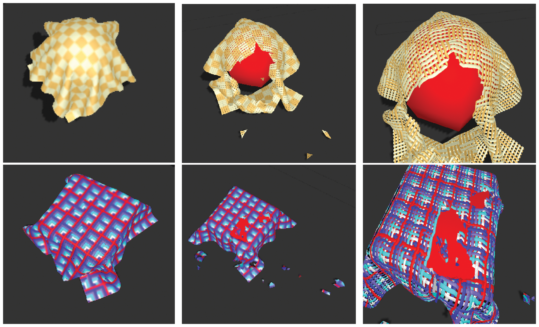
As shown in Figure 2(a), the realistic simulation of woven fabrics depends on the behaviors of yarns and the interlaced structures. The yarn-yarn interactions at the meso scale are the key to obtaining accurate results. Due to the interlaced mass-spring system, the interactive changes of the weave, simulation of behaviors of yarns becomes possible. These allow for real-time weaving design in virtual cloth fitting.
Applying particle systems to woven fabrics at the yarn scale. (a) A 5 × 5 region of woven fabric with five weft yarns and five warp yarns observed by a microscope, (b) illustration of (a), (c) single particle system representation of (a), (d) particle pair system representation of (a).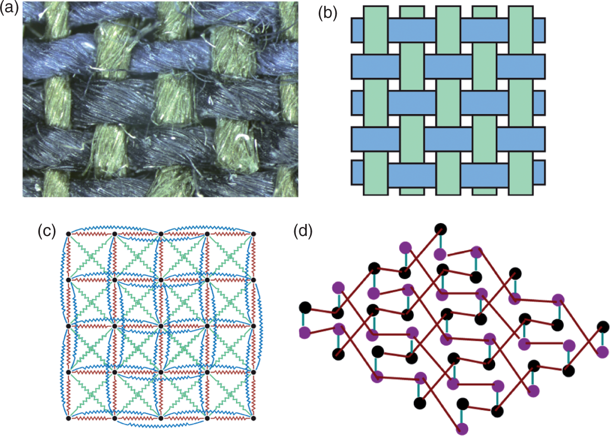
Woven fabric simulation at the macro scale has been represented in a variety of different ways in the literature 1 – 6 and some proposed the thread simulation at the yarn scale.7,8 The most straightforward way for simulating the behavior of woven fabrics is to apply particle systems 9 – 14 at the meso scale. This is because it is fast, versatile, facilitates implementations of various behavior equations and allows direct access to state information (interaction with the object’s position and speed) for enforcing constraints and manipulation.
In general, a woven fabric exhibits three types of motions: in-plane stretch/compression, in-plane shearing (trellising) and out-of-plane bending. These motions can be modeled as particle motions by either energy functions or spring-dampers. Breen et al.’s particle system9,10 allocates the particles at the weave points, where a particle ideally represents a yarn crossing. Each interlacing weave point in Figure 2(b) contains a particle. The interactions among particles are described via energy functions. Instead of energy functions, Provot
14
describes the interactions among particles using springs. For example, a 5 × 5 woven fabric with five weft yarns and five warp yarns shown in Figure 2(b) is represented as a 5 × 5 dynamics system of single particles interconnected with springs shown in Figure 2(c). Each particle is connected with three types of springs: 1) stretch springs (structural springs), the main springs in the fabric; 2) shear springs, providing resistance to shearing and maintaining the diagonal shapes of the woven fabric; and 3) bend springs (flexion springs), providing resistance to the cloth folding in on itself and helping to control the bending of woven fabric connecting particles that are two particles apart. However, the dynamics system of particles at the meso scale has disadvantages:
A single particle at yarn crossings can not provide independent behaviors for both the weft and warp directions. Single particle systems can not represent the interlaced crimp structures of woven fabrics, which are important features formed by weaving.
Motivated by the above requirements, we construct a flexible dynamics system of particle pairs to provide independent physical behaviors in weft and warp directions while maintaining the constraints between the pairs of particles. For example, the 5 × 5 woven fabric with five weft yarns and five warp yarns is represented as a 5 × 5 dynamics system of particle pairs rather than single particles using our approach as shown in Figure 2(d). Another problem using single particle systems at the meso scale is the problem of tearing. One way to overcome this is to define a length (or percentage of rest length) that will cause the spring to break. To solve this problem, we introduce the connectivity matrix, so that the tearing can be treated as a disconnection of particles and the original status can be treated as the case that all particles are connected together. Some simulation results using the particle pair system with interlaced structures and tearing are shown in Figure 1.
The work presented in this paper has three main contributions:
We introduce the particle pair system, an interlaced mass-spring dynamics system for woven fabrics. It treats woven fabrics as interlaced crimp networks of weft and warp particles. Each weave point (yarn crossing) of the woven fabric is represented as a particle pair rather than a single particle. This provides independent behaviors of particles in the weft and warp directions. Particles are connected dynamically according to connectivity matrices. It allows the tearing. Particle tessellation. The atoms of a particle pair system are the particle pairs, flexible representations that can be tessellated to panel quads at the macro scale, interlaced yarn segments at the meso scale and intertwisted fibers at the micro scale according to the LOD (level of detail) value (which is extracted from the view distance using equation 24 and 25).
The particle pair system can be easily implemented in the newer GPUs (Graphics Processing Units) supporting hardware tessellation, and using current pipelines. For current pipelines, we can achieve more than 100 FPS (frames per second). This allows for large-scale physical animations of woven fabrics that maintain the geometric variances of real 3D yarn and fibers.
Particle pair dynamics
Particle pair system
Woven fabrics are comprised of two sets of yarns, the warp and the weft. They are organized into two perpendicular directions on the cloth surface. Each weft yarn and warp yarn consist of particles. To distinguish the weft and warp, we use the subscript ‘w’ to denote the elements of weft and the subscript ‘r’ to denote the elements of warp.
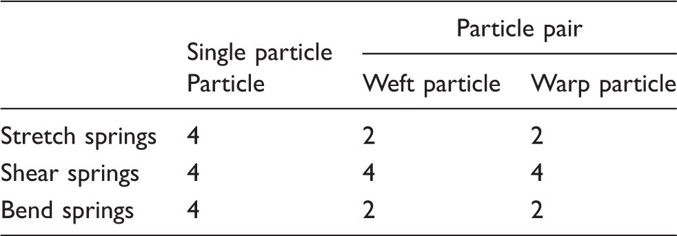
We denote the weft particle at the weave point (s,t) as jw(s,t) and the warp particle at the weave point (s,t) as jr(s,t). The particle at (s,t) (in the center of Figure 3(a)) is divided into two particles for the weft and warp directions respectively, as shown in Figure 3(b). The four stretch spring-dampers (in red) connected to this particle are divided into two groups: two for weft and two for warp. The four shear spring-dampers (in green) connected to this particle are divided into two groups of eight shear spring-dampers: four for weft and four for warp. Similarly, the four bend spring-dampers (in blue) are also divided into two groups: two for weft and two for warp.
Comparison between a single particle and a particle pair. Stretch springs are in red, shear springs in green and bend springs in blue: (a) a single particle and (b) a particle pair.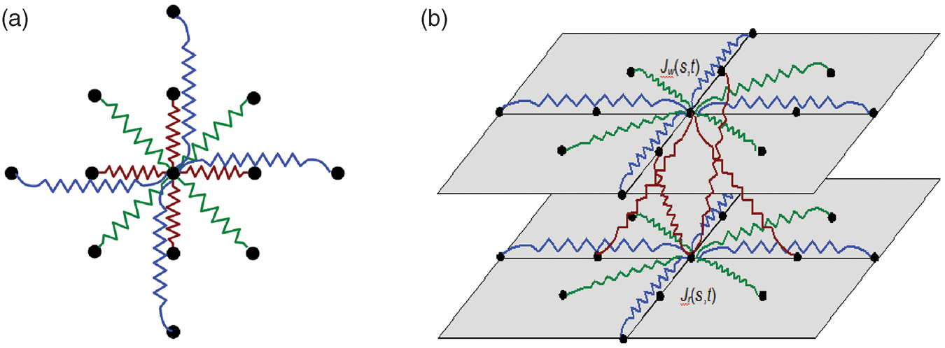
Based on the denotation of weft particles and warp particles, the t-th weft yarn can be denoted as a set of weft particles Yw(t) = {jw(s,t)|s∈ [0,m − 1]} and the s-th warp yarn can be denoted as a set of warp particles Yr(s) = {jr(s,t)|t∈[0,n − 1]}, where m is the number of warp yarns in the woven fabric and n is the number of weft yarns in the woven fabric. As shown in Figure 4, an illustration of the t-th weft yarn, the weft particle jw(s,t) is connected to two nearest neighbor weft particles: jw(s − 1,t) and jw(s + 1,t) using stretch spring-dampers and is connected to two weft particles jw(s − 2,t) and jw(s + 2,t) using bend spring-dampers.
Illustration of the weft particles and spring-dampers in the t-th weft yarn.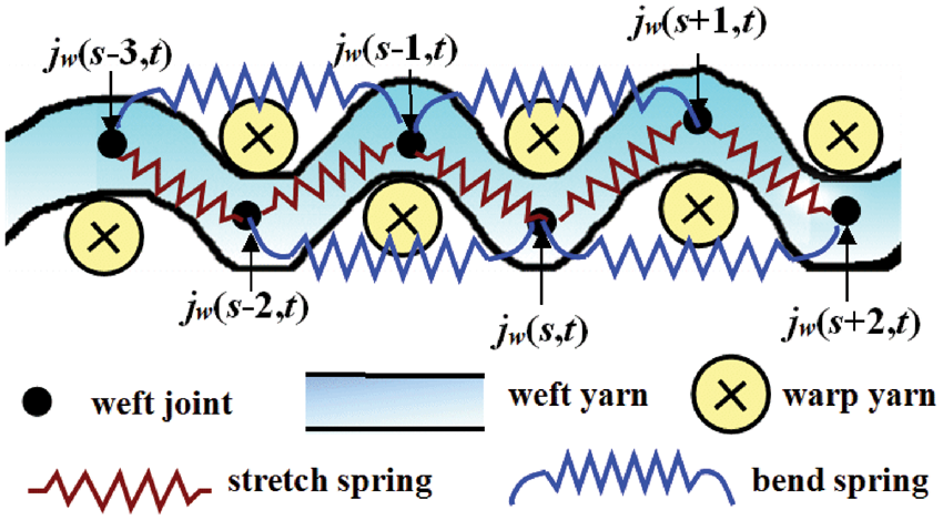
As shown in Figure 5, a woven fabric interlaced by m warp yarns and n weft yarns is constructed as a crimp network of 2 × m × n particles (m × n pairs), consisting of m × n particles for weft and m × n warp particles for warp. Table 1 provides a comparison between a single particle system and a particle pair system. Table 2 provides a comparison between a single particle and a particle pair. These particle pairs are the atoms of the dynamics system. They are subjected to forces, such as gravity, wind and drag, spring force and damping force to maintain the overall shape of the woven fabric and collision constraints to prevent interpenetration with the environment. The weft particle jw(s,t) contains the following attributes: position, pw(s,t); velocity, vw(s,t); acceleration, aw(s,t); mass, mw(s,t); and external forces, (fe)
w
(s,t). The warp particle, jr(s,t), also has these attributes: position, pr(s,t); velocity, vr(s,t); acceleration, ar(s,t); mass, mr(s,t); and external force, (fe)
r
(s,t).
The interlaced particle pair system for woven fabric simulation. The three subfigures are an illustration of stretch spring-dampers (left subfigure), bend spring-dampers (middle subfigure) and shear spring-dampers (right subfigure) in the particle pair system. Comparison between a single particle system and a particle pair system Comparison between a single particle and a particle pair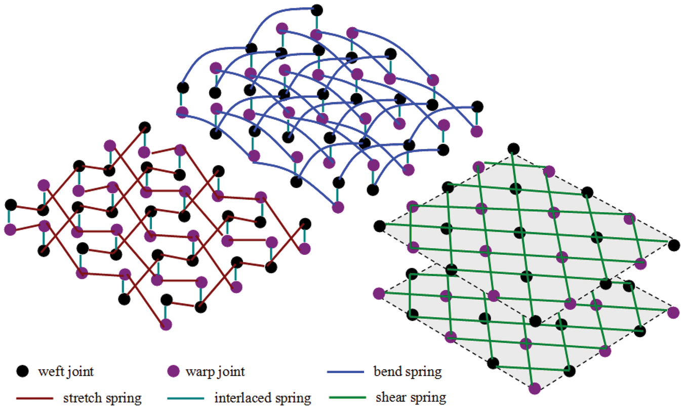

Spring and damping forces for weft particle
As shown in Figure 3(b), we denote the vector from the weft particle, jw(s,t), to the weft particle, jw(s + Δs,t + Δt), as xiw(s,t,Δs,Δt), and denote its normalized vector as x
i
w
(s,t,Δs,Δt), such that:

The spring force (Hooke’s Law: f = −kΔx) and the damping force of a single spring-damper applied to the weft particle jw(s,t) by another weft particle jw(s + Δs,t + Δt) can be denoted as:
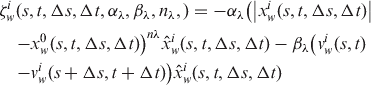
Stretch spring-damper: The weft particle, jw(s,t), has stretch spring forces (by Hooke’s Law: f = −kΔx) and stretch damping forces applied from two weft particles, jw(s − 1,t) and jw(s + 1), such that:

Shear spring-damper: The weft particle jw(s,t) has shear spring forces and shear damping forces applied from four weft particles, jw(s − 1,t − 1), jw(s − 1,t + 1), jw(s + 1,t − 1) and jw(s + 1,t + 1), such that:


It is defined to support structure buckling (folds or wrinkles) of soft woven fabrics, becoming:

Bend spring-damper: The weft particle jw(s,t) has bend spring and bend damping forces applied from two weft particles jw(s − 2,t) and jw(s + 2,t), such that:

Spring and damping forces for warp particle
Similar to weft particles, we denote the vector from the warp particle jr(s,t) to the warp particle jr(s + Δs,t + Δt) as xir(s,t,Δs,Δt) and denote its normalized vector as x
i
r
(s,t,Δs,Δt) such that:


Stretch spring-damper: The warp particle, jr(s,t), has stretch spring and stretch damping forces applied from two warp particles, jr(s,t − 1) and jr(s,t + 1), such that:

Shear spring-damper: The warp particle, jr(s,t), has shear spring and shear damping forces applied from four warp particles, jr(s − 1, t − 1), jr(s − 1, t + 1), jr(s + 1, t − 1) and jr(s + 1, t + 1), such that:
Bend spring-damper: The warp particle, jr(s,t), has bend spring and bend damping forces applied from two warp particles, jr(s,t − 2) and jr(s,t + 2), such that:

Interlaced forces
Apart from spring and damping forces for weft particles and warp particles, virtual interlaced forces are introduced by adding a spring-damper between the weft particle jw(s,t) and the warp particle jr(s,t) to provide slight sliding between the pair of particles while maintaining distance constraints between them. We denote the vector from the weft particle jw(s,t) to the warp particle jr(s,t) as yiw(s,t) and denote its normalized vector as yiw(s,t), such that:

Therefore, the interlaced force (fi)
i
w
(s,t) of the spring-damper for the weft particle, jw(s,t), and the interlaced force (fi)
i
r
(s,t) of the spring-damper for the warp particle, jr(s,t), are:


The coefficients α and β are determined by the interlaced rule at weave point (s,t). They can be set to six possible values. These values can be derived from a total of 32 cases of 5-bit weave encoding. In the cases with encoding (01111 and 10000), the weft and warp yarns are interlaced tightly, so the interlacing coefficients are the largest. In the cases with encoding (00000 and 11111), the weft and warp yarns are straight, so the interlacing coefficients are the smallest. The six possible values for a total of 32 encoding cases can be found in Appendix 1.
Total forces and acceleration
The total force f iw (s,t) for the weft particle, jw(s,t), and f ir(s,t) for the warp particle, jr(s,t), at the i-th frame become:


Motion integration
The particle’s equation of motion resulting from applying the external forces is integrated using Verlet integration,
16
a velocity-less integration scheme. Instead of use each particle’s current position and velocity, Verlet integration
16
uses its current frame position, pi(s,t), its previous frame position, pi − 1(s,t), and the elapsed time, τ, (the time between the current frame and next frame) to compute its position at the next frame, pi + 1(s,t). Because it does not explicitly store the velocity of each particle, it is much more stable than the Euler integration when particles are translated to satisfy constraints.


Tearing
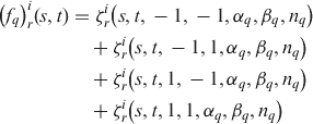
In order to support special physical effects such as tearing in the interlaced particle pair system, we establish two connectivity matrices, one for connectivity between weft particles and one for connectivity between warp particles, such that:

The connectivity matrix Cw for weft particles is a matrix of dimensions (w − 1) × h. The element cw(s,t) describes the connection between weft particles, jw(s,t) and jw(s + 1,t). The connectivity matrix Cr for warp particles is of dimensions w × (h − 1). The element cr(s,t) describes the connection between warp particles, jr(s,t) and jr(s,t + 1). Each element in the connectivity matrices is 0 for disconnected particles and 1 for connected particles. Therefore, the equations 3, 5, 8 and 10 can be rewritten by multiplying the connectivity term to form:




A significant difference between the single particle system and the particle pair system is that the particle pair system breaks the connectivity in the weft and warp directions separately.
Particle pair tessellation
After the physical motions of particles and the collision detection/self-collision detection of particles, we obtain the accurate positions for weft and warp particles. These particles are basic physical elements without geometric properties. They will be tessellated to form desired geometry for final rendering as shown in Figure 6. The desired geometric form of the weft particle jw(s,t) is determined by the LOD value (tessellation factor) di(s,t) at the current frame. Likewise, the desired geometric form of the warp particle jr(s,t) is determined by the LOD value di(s,t) at current frame. This forms:
Tessellation of weft and warp particles at varying LOD values. The upper row depicts the tessellation as quads; the middle row depicts the tessellation as yarn segments; the lower row depicts the tessellation as fibers.

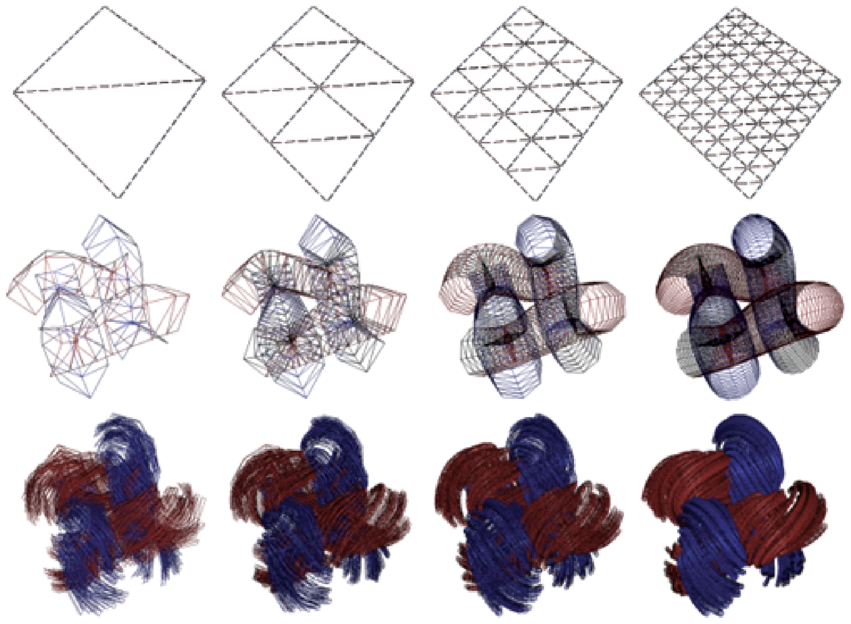
The LOD value dw(s,t) for weft particles and dr(s,t) for warp particles are proportional to distances from their positions, piw(s,t) and pir(s,t), to the eye position of the camera, pe, and inversely proportional to the average distances, lw and lr, between two neighboring particles. These LOD values are computed as:


Implementation
The simulation of woven fabrics includes two steps: physics computation of particles and geometry generation using GPU tessellation.
Physics computation
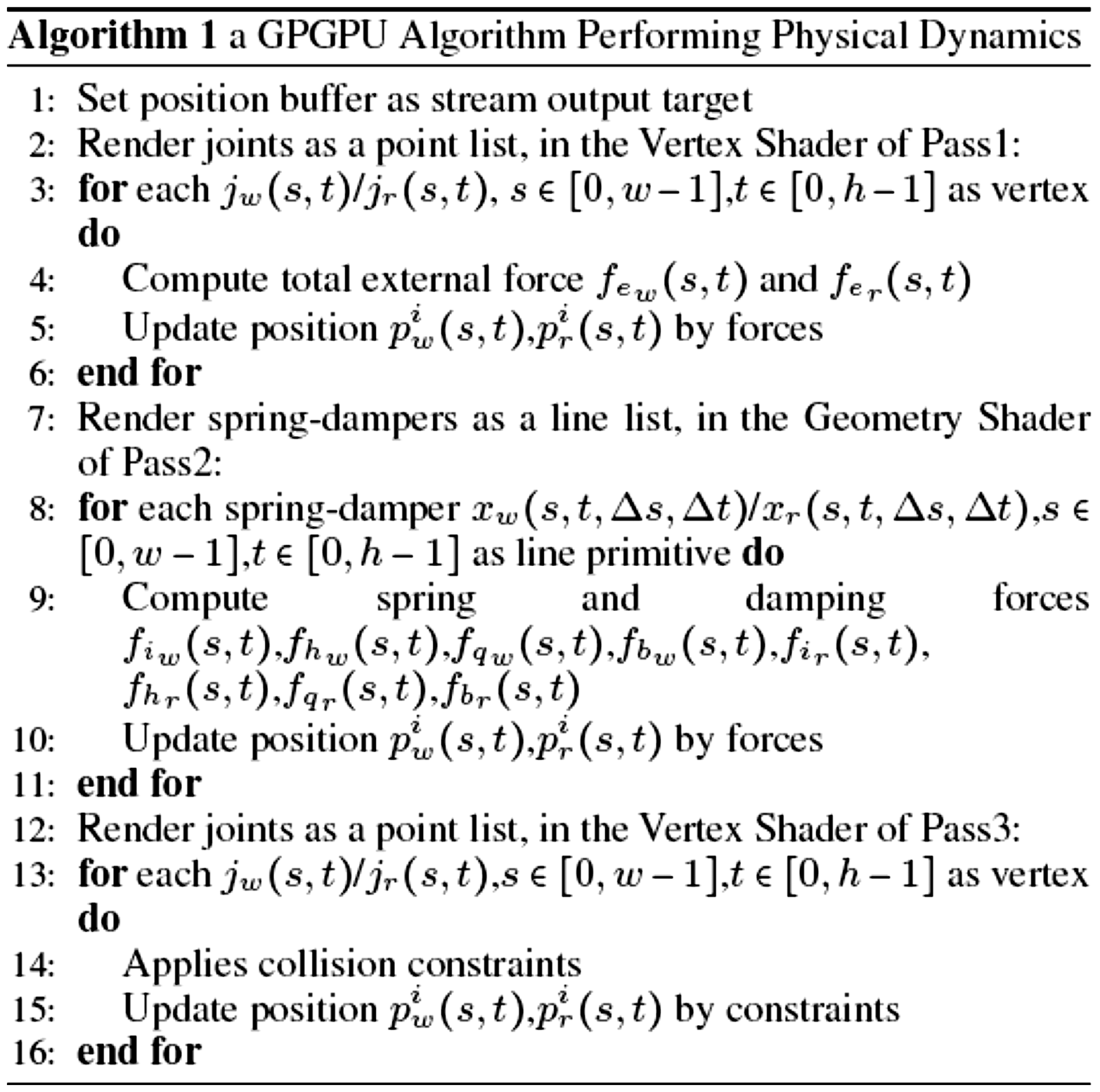
Although the current GPUs are beginning to support physics simulation with the advent of engines like PhysX, these physics engines are limited to the simulation of cloth at the macro scale. We introduce a GPGPU algorithm as shown in Algorithm 1 (using the GPU for general purpose computing to calculate the physical dynamics) as rewritten from Zeller’s White Paper.17,18 In the algorithm, the particles are stored in a buffer during initialization and, at each frame, processed through several general compute passes. Forces are applied to each particle in parallel. Similarly, collision detection is enforced at each particle based on our previous work.19,20 Therefore, the first and third passes of Algorithm 1 are implemented as vertex shaders in two single passes. Applying spring and damping forces can also be done in parallel, but each spring-damper involves two particles. Therefore, it is implemented as a geometry shader in another single pass.
Geometry generation
The newest generation GPUs supports hardware tessellation in the graphics pipeline by providing three new stages: the tessellator, the hull shader and the domain shader. These stages are used to generate the final high-detail geometries (panel quads/yarn segments/fiber assembles) from the particles according to LOD values.
Hull shader: The hull shader is rewritten from the one for the ‘SubD11’ example of the Microsoft DirectX SDK. The input of the hull shader includes the indices and control vertices of particles (positions of the particles by physics simulation). The hull shader loads the pre-computed data of the particles from the buffer, computes the six tessellation factors derived from equations 24 and 25 and passes them to the tessellator.
Tessellator: The tessellator stage subdivided a domain (the particle) into many smaller objects (panel quads/yarn segments/fiber assembles). For example, particles are tessellated into a number of small quads if the tessellation factor determines it is in the macro scale. The tessellator generates the UV coordinates of vertices and the surface topology and passes them to the domain shader.
Domain shader: The domain shader is rewritten from the ‘BezierEvalDS’ function of the same ‘SubD11’ example used in the hull shader stage. It does not, however, use the Bernstein terms of Bezier to compute the final position. It computes the final position according to three custom mapping functions, which map the parametric positions in the UV domain to one of the three final geometries (panel quads/yarn segments/fiber assembles) as shown in Figure 6.
Experiments and results
The particle pair system used for woven fabric simulation at the meso scale is shown in Figure 7. We used Direct3D 10 and HLSL to perform general purpose computation for simulation of physics dynamics, and ARP (adaptive refinement pattern) [BS0] to perform pre-tessellation for the geometric generation of particles. The experiment was implemented on a NVIDIA GTX 130M g mobile GPU.
Snapshots of particle pair system for physical dynamics of woven fabric. (a) and (b) Draping of a piece of woven fabric at the panel scale and at the yarn scale; (c) and (d) tearing of a piece of woven fabric at the panel scale and at the yarn scale; (e) and (f) draping of a piece of woven fabric at the panel scale and at the yarn scale; (g) (h) draping of a tie consisting of two pieces of woven fabric at the panel scale.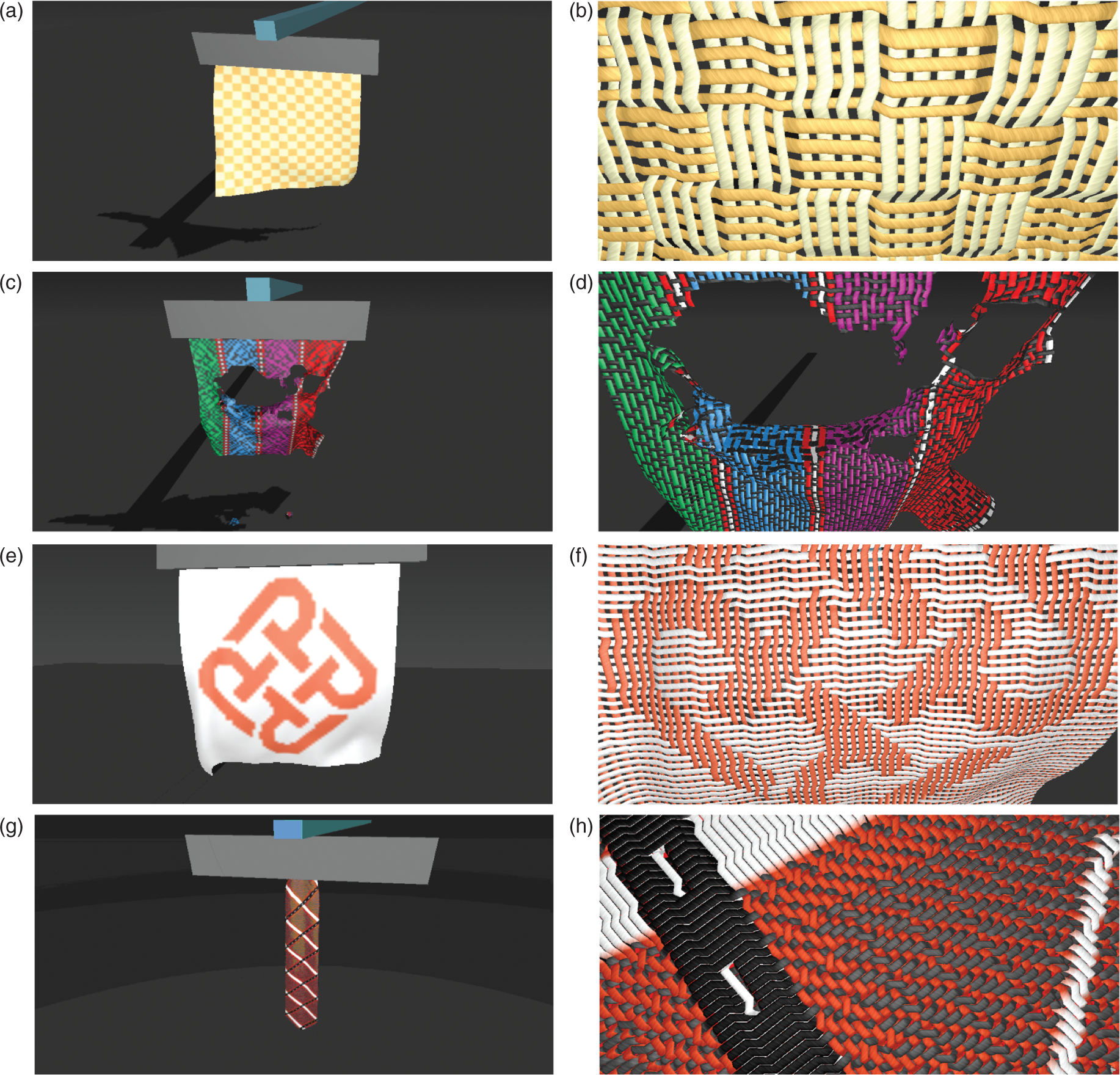
For comparison, an alternate single particle system has also been implemented. We have carried out a number of tests for assessing the accuracy of our particle pair system. At the macro scale (the panel levels), we did not notice a significant difference between the particle pair system and the single particle system. However, the particle pair system can obtain accurate positions, pw(s,t) and pr(s,t), for weft particles, jw(s,t), and warp particles, jr(s,t), respectively, rather than one position as obtained using the single particle system. In addition, we can obtain interlacing details at the meso scale as shown in Figure 7(b), Figure 7(d) and Figure 7(f) and obtain a smooth appearance at the macro scale as shown in Figure 7(a), Figure 7(c) and Figure 7(e).
Runtime performance comparison between the particle system and the particle pair system

# Particles, the number of particles.
The result shows that the interlaced particle pair system provides a simple yet effective method for realistic simulation of woven fabrics in real time. When an external force like wind is added, the particle pair system continues to react in a very realistic manner. Figure 7(g) and Figure 7(h) show scenes when the particle pair system is applied to simulate the physical dynamics of a tie consisting of two pieces of woven fabrics at the panel level and at the fiber level. Figure 7(i) and Figure 7(j) show two examples of woven fabrics simulated at the fiber level.
For the comparison between a real woven fabric and a simulated one, we take photos in the microscope to show the interlaced structures of the real woven fabrics. The comparisons are performed respectively at 1 mm and 2 mm corresponding to the view distances as shown in Figure 8. The particle pair system can obtain accurate positions for weft and warp particles respectively. It overcomes conventional single particle systems in that we are able to simulate the interlaced structures at the meso scale during fabric deformation.
Comparison between simulated results and photos taken in the microscope. (a) Simulated result at 2 mm; (b) photo taken at 2 mm in the microscope; (c) simulated result at 1 mm; (d) photo taken at 1 mm in the microscope.
Conclusion and future work
The goal of our research was to establish a meso scale dynamics system for woven fabrics simulation. This led to accurate simulation of woven fabrics at varying scales. In this paper, we introduced the particle pair system, an interlaced mass-spring dynamics system for woven fabric simulation. The atom of our system is the particle pair, a flexible representation that can be tessellated to form panel quads at the macro scale, interlaced yarn segments at the meso scale and intertwisted fibers at the micro scale, according to the LOD value. This allows for special physical effects such as tearing. The limitation of our work is that it only applies to woven fabrics. In our future work, we will generalize the particle pair system by adding support for complex interlaced forces so that it can be used with other fabrics.
