



Abstract
The moisture management property of compression bandages is a critical factor influencing the state of well-being and compliance of patients with venous and lymphatic disorders. The thermal resistance and water vapor transmission rate of compression bandages were assessed using a limb model, which allows bandage application under tension and provides valuable insight on moisture distribution across the entire ensemble under simulated wear conditions. The performance of eight commercially available two- and four-layer compression bandages was evaluated based on measurement of physical parameters, such as thickness and mass per area, moisture sorption, air permeability, water vapor permeability, and moisture distribution during the simulated wear test. The gravimetrically determined water vapor transmission of the different bandages varied from 279 to 341 g m−2 h−1. Low air permeability of padding or cohesive can indicate possible moisture barrier properties, which could cause undesirable moisture accumulation inside the bandage. Robust reproducibility of the test, along with rapidity and ease of manipulation, allows comparison between the individual products and could provide the basis of dressing performance standardization.
Over the last decade external compression has remained the single most effective means of treatment of chronic venous and lymphatic insufficiencies.1,2 Venous disorders require prolonged treatment that involves continuous wearing of compression bandages. Strategies of compression therapy are solely focused on individual symptom consideration, and adequate compression system selection, giving little attention to the bandages’ moisture management performance. Recently, studies to assess the thermoregulatory properties of compression have been published; however, at present there is no common agreement between various European standards on compression bandage performance.3,4 The main properties, based on which the bandage is defined to meet clinical requirements, are tension, extensibility, sub-bandage pressure, and the force required for the bandage to restore its original state, as well as mass per unit area, which determines the thickness.
The importance of the evaluation of moisture management properties becomes more meaningful with respect to duration of wear. The total thickness of the dressing, depending on the type and the mode of its application, that is, degree of overlapping, can reach more than 1 cm. Worn for a prolonged period of time with a relatively low frequency of dressing changes, moisture management properties of the dressings become very critical. To assure cooling and to prevent moisture buildup, moisture vapors must escape the bandages. If the garment acts as a barrier for water vapors, condensation is very likely to occur. 5 Condensation on the inner side of the dressing might result in overhydration and even maceration of the underlying tissues.6,7 The latter is highly undesirable in the vicinity of the vulnerable tissues, as it facilitates wound expansion. Furthermore, a moist and warm environment creates favorable conditions for microbial growth. In the absence of published data, it can be assumed that the overheating of underlying tissues and, perhaps, excessive sweat production, is the plausible scenario. Thus, accurate assessment of the moisture management properties of dressings is important to improve their performance, which will have a favorable impact on the healing process. 8 Furthermore, proper perspiration handling by the dressing will reduce significantly the frequency of dressing changes and, in doing so, the cost effectiveness of the patient care. 9
Currently, there are many standard test methods in use to study water vapor transmission in textiles, for example, the cup method (ASTM Method E96-80), 10 gravimetric methods (ISO 15496), 11 the sweating guarded hot plate (ISO 11092), 12 and the standard ASTM F2298, which uses the dynamic moisture permeation cell. 13 Regardless of its simplicity and widespread acceptability, the cup method has several substantial drawbacks. A layer of still air between the fabric and water surface has relatively high resistance for water vapor diffusion. During the test, the amount of liquid and water vapor pressure in the cup continuously decrease, yielding certain inaccuracy of the result. In addition, the method does not account for heat transfer during evaporation. All of these problems can be eliminated in a sweating hot plate method, which accounts for both heat and mass transfer. A comprehensive review and critical comparison of relevant methods for measuring water vapor permeability of fabrics has been published by McCullough et al. 14 Significant progress could be achieved by the adaptation of test procedures in testing of multilayer assemblies, which allow better assessment and interpretation of material differences15,16 The influence of air gaps in multilayered assemblies and theoretical models also has been reported in the literature. 17
In addition, the use of manikin systems has been extensively studied and significant progress has been reported in studies of thermoregulatory properties of garments.18–20 As a disadvantage, the use of manikin systems is rather complex and simpler laboratory methods would support wider distribution of such analyses.
In any case, the plane-guarded hot plate approach is not suitable for compression bandages due to the peculiarities of their application. In order to achieve the required sub-bandage pressure, the application of bandages requires a certain degree of stretching, as well as a degree of overlapping, which through the curved surface geometry results in compression and a very tight contact between the layers. This mode of application demands a cylindrical model, while use of a plane geometry for characterization of materials is not appropriate to simulate wear conditions of compression bandages. 3 Advantages of cylindrical geometries already have been proven in the literature.21,22
Herein we propose a limb model to measure the thermal resistance and water vapor transmission rate (WVTR) in multilayer assemblies of various dressings. The model is based on the principle of the guarded hot plate with some additional features. To generate the water vapor flux, a thin removable pouch of multiple usages was accustomed. The test provides valuable insights on heat and moisture transport through the layers of compression bandages, as it allows not only one to measure the transmission rate of the entire ensemble, but also reveals barrier properties of particular layers.
Materials and methods
Characteristics of bandages: mass per area mA, thickness d, air permeability D, air resistance 1/D, water vapor transmission rate (WVTR), Ret values, and moisture content MC (values ± standard deviation)
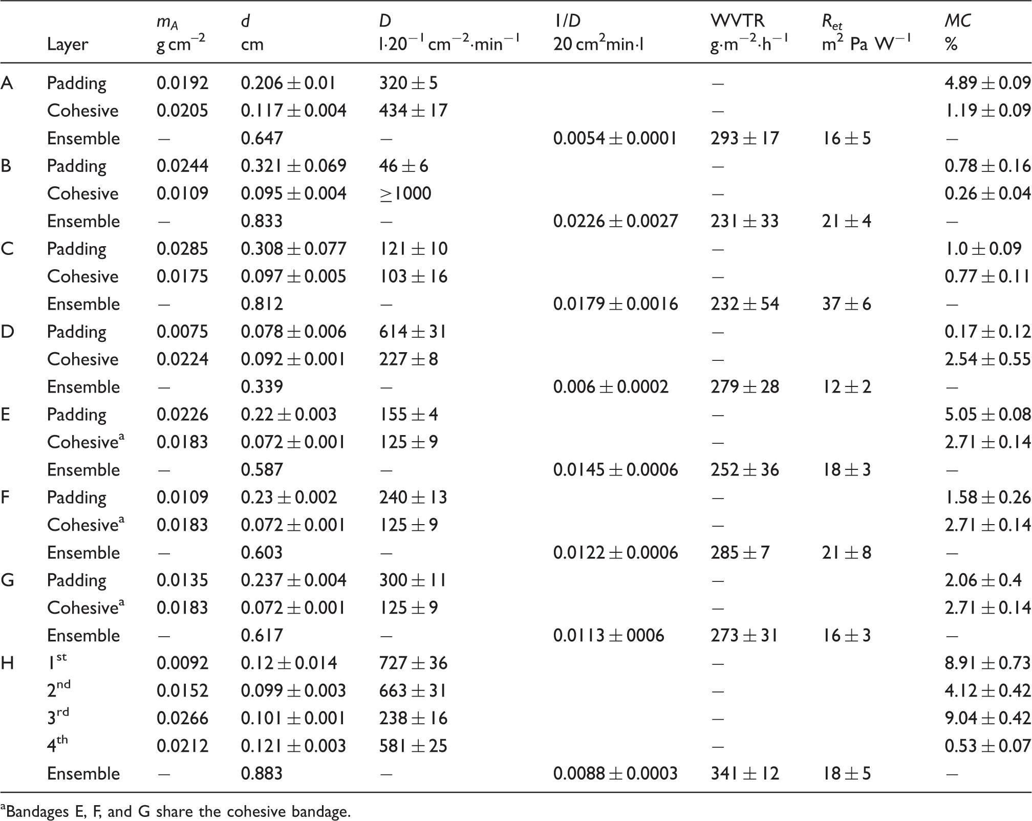
Bandages E, F, and G share the cohesive bandage.
Fabric mass per area, mA (g cm−2), was determined according to BS EN 12127. 23 While mass determination can be performed with high accuracy, considerable variability of the mass per area is caused by the high extensibility of the materials and the adhesive behavior of the samples. An estimate for the inaccuracy of the results can be given with ±10–15% of the mean.
Thickness d (cm) measurements were done according to ISO 5084 24 on a DM 100 gauge with a total load of 25 cN cm−2.
Air permeability, pa (l 20 cm−2 min−1), of double layer of bandages was measured according to EN ISO 9237:1997 25 with a test head of 20 cm2 and pressure difference of 100 Pa.
Moisture content, MC (%), was determined according to ASTM D2495.
26
Due to the adhesive coating of some padding bandages, the drying temperature was reduced from 104 to 75℃. MC was calculated according to the following equation:

In which Wc(g) represents the mass of the sample conditioned at 65% relative humidity (R.H.) and Wd(g) represents the mass of the dried sample.
Limb model
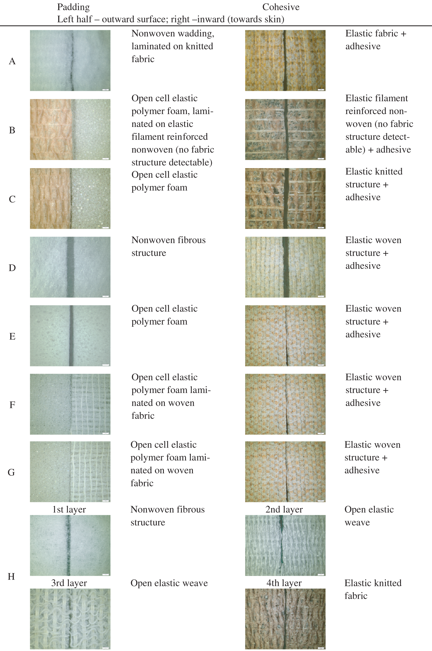
Bandage characteristics – microphotographs of paddings and cohesives A–H. The white scale bar represents 1 mm.
The limb model consists of two parts: an upper of conical shape and a bottom of cylindrical shape (Figure 2). The geometry corresponds to size M (scale S, M, M/L, L, XL, XXL) and size 2 (scale 0–6) for commercial supporting braces. There are two heating units located on the upper and bottom parts. Each unit includes the heating front (T1, 5 cm × 10 cm) and backside (T2, 10 cm × 15 cm) mats, which are kept isothermally (T1 = T2) toward one another with the aid of power supplies (EX355, Thurlby Thandar Instruments, UK, and L30-1, Farnell Instruments Ltd, UK, respectively). The front heater is covered by a copper plate of the same size. K-type polytetrafluoroethylene (PTFE) thermocouples (T.M. Electronics, UK) and humidity sensors HIH 4000-001 (Honeywell International, USA) are connected to data loggers TC-08 (Pico Technology, UK). All manipulations on the limb were done in the climate-controlled chamber (BBC Brown Boveri, USA) at a defined temperature ±1℃ and humidity ± 2–5% R.H.
Limb geometry: (a) circumference measured 15 cm above the angle of bending: 43 cm; (b) circumference measured 5 cm above the angle of bending: 39 cm; (c) circumference below the knee: 35 cm; (d) length from the top to the bending point: 25 cm; (e) length from the bending point to the bottom: 27 cm.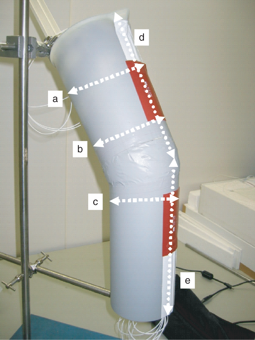
The bandages were applied on the upper part of the limb, maintaining the sub-bandage pressure in the range of 30–40 mm Hg and 50% overlapping; as a result, the total number of layers doubles. Thus, the resulting ensemble over the tested area (metal plate) consisted of four layers in the case of the padding-cohesive system (Materials A–G), and of eight layers in the case of material H.
Dry heat loss
The forward heat flux produced by the top heater passing through the layers of bandages served as an indicator of heat loss. The backward heat loss is compensated by the heating mat, which is placed on the inner wall of the limb, behind the front heater. The backside mat is of a larger size to compensate for heat loss from the edges of the front heater. The heater mats are independently controlled to maintain isothermal heating. The unidirectional air flow was applied perpendicular to the tested area. The air stream was controlled with aid of a Testo 452 anemometer.
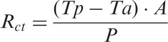
Thermal resistance Rct (m2 K W−1) was calculated according to the following equation:
12
Water vapor transmission rate
The setup was designed in such a way as to assure continuous streaming of water vapors through the layers of bandages, thus maintaining the steady-state water vapor pressure condition. To exclude thermal transfer and to compensate only evaporative heat loss, the metal plate was kept at the same temperature as the ambient temperature (26 ± 1℃).
A custom-made pouch with an inner wall made of thin water impermeable plastic film and outer wall made of PTFE membrane (pore ø = 0.45 µm) served as a source of water vapor flux. A cotton fabric, size 5 cm × 10 cm (100% cotton, plain weave, scoured, and bleached, mass per area 0.0123 ± 0.008 g cm−2, warp density 47 y cm−1, weft density 28 y cm−1), which corresponds to the size of metal plate, was fitted inside the pouch and served to retain the liquid upon filling the pouch with water. Rapid wicking and high moisture pick-up properties of cotton assured rapid distribution of water over the entire area. The amount of water added was calculated to achieve full wetting of the cotton fabric. As liquid was added from the top and as the dimensions of the fabric are much smaller than the height of spontaneous capillary wicking, differences in water evaporation due to gravimetric effects can be neglected. The plastic film is facing the metal plate and the PTFE membrane is in immediate contact with the bandage. The bendable film base allows good fitting on the convex surface of the limb. The pouch is fixed on the limb with the aid of adhesive tape in a way that the margins of cotton fabric match the plate. In this arrangement, the water vapor stream is permitted in one direction – from the pouch through the layers of bandages. The rate of evaporation and the rate of liquid supply were determined as followed: the pouch was filled with 1 ml of water, which corresponds to moisture pick-up of cotton of the size 5 cm × 10 cm, and was placed on the balance, where a weight decrease at 26℃ and a fixed R.H. in the range of 52 ± 4% were recorded. The weight loss that occurred in the first 15 min determined the amount of water that had to be added in order to maintain steady-state evaporation during the test. Thus, in the beginning of the test, 1 ml of water was fed with the aid of the long thin tip inside the pouch to saturate the cotton fabric, and then 0.2 ml of water was added every 15 min during the test, with a total duration of 60 min. The amount of water evaporated is calculated by the difference between the amount of water fed into the pouch and the amount remaining after the test.
The final content of water in the pouch was checked at the end of the experiment gravimetrically. From the detailed analysis of the experimental data it was found that by regular addition of water, the volume of water in the pouch has to be maintained at the level of at least 0.1 ml to maintain steady-state evaporation. Under such conditions, 100% R.H. was recorded by the sensor placed on the surface of the membrane. Stable temperature conditions at the front heater (T2 and T3, Figure 3) were used to prove quasi-stationary conditions. Relative standard deviation between repetitive experiments of WVTR based on gravimetric results was dependent on the material used and varied between 3% for bandage system F and 23% for bandage C.
Schematic diagrams of the heating block (a) and sensor position in four-layer bandage ensembles (b). T and H denote temperature and humidity sensors, respectively.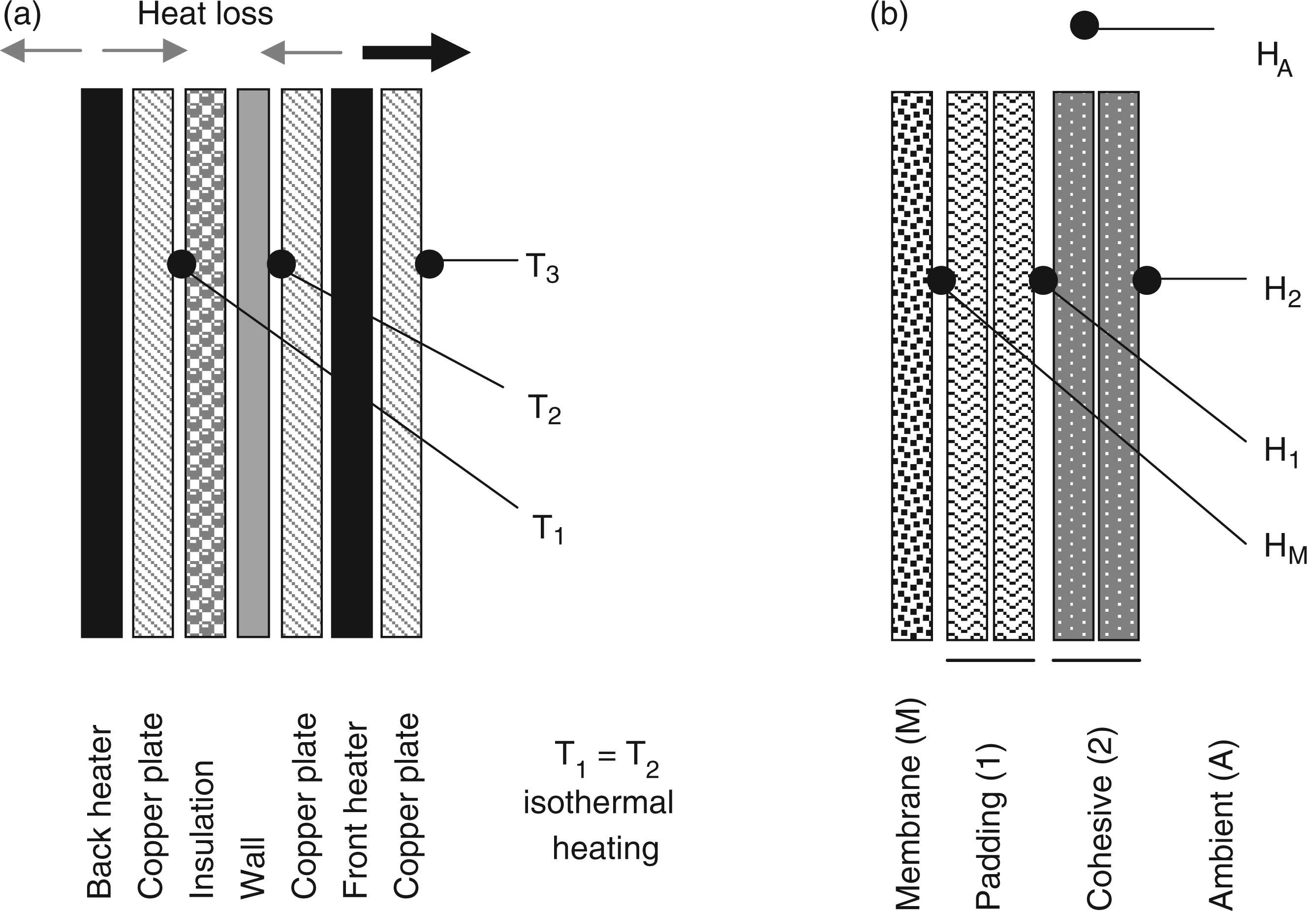
A thin removable pouch adapted to generate water vapor flux has certain advantages over the cup method. The main drawback of the cup method consists of the high water vapor resistance of still air between the fabric and the liquid, which sometimes could be even higher than that determined for the fabric itself. The approach used in this work overcomes this problem by excluding the air gap and by maintaining steady-state evaporation. Pulse injections of water may not assure ideally equal distribution of the liquid over cotton during the test. The latter can be improved by continuous liquid supply with the aid of a peristaltic pump.
To distinguish between the evaporative and the dry heat losses, the metal plate was kept at 26 ± 1℃, that is, isothermal to the ambient temperature, and the electrical power was applied to compensate related evaporation heat loss. Moisture distribution across the multilayer system was monitored by placing the sensors on the surface of the membrane and between the layers of bandages.
The WVTR (g m−2 h−1) was calculated based on the difference in the add-on amount of water and water remaining after the test by weighting the pouch according to the following equation:
10

Values for Ret were calculated using water vapor pressure data for 26℃, the electrical power used to maintain steady-state conditions at the front heater, and the particular R.H. conditions used in the respective experiment. No corrections for ΔHe were used.
Results and discussion
Dry heat loss in multi-layer compression bandages
The values of thermal resistance (Rct) calculated for ensembles of bandages varied from 94 to 125 10−3 m2 K W−1 at an air stream of 0.1 m s−1 and from 70 10−3 to 99˙10−3 m2 K W−1 at 1 m s−1 (Figure 4). Among the bandages tested, bandage D had the lowest absolute values of Rct (94 10−3 m2 K W−1), whereas the highest value of Rct was determined for bandage B (125 10−3 m2 KW−1). As can be seen from Figure 4, the major drop of Rct for all the bandages tested occurred upon increase of air speed from 0.1 to 0.5 m s−1, which corresponds to decline by 14–28% of the value determined at 0.1 m s−1. A further increase in air speed from 0.5 to 1 m s−1 caused a relatively smaller Rct drop from 20 to 34% of the value determined at 0.1 m s−1. Bandage A, possessing relatively high thermal resistance of 120 10−3 m2 K W−1, exhibited limited resistance to wind upon increase of the air speed from 0.1 to 1 m s−1 and Rct dropped down to 79 10−3 m2 K W−1. The lowest drop of Rct from 125 10−3 to 108 10−3 m2 K W−1 and, therefore, the highest resistance to wind was measured for bandage B.
Thermal resistance of bandages as a function of wind speed.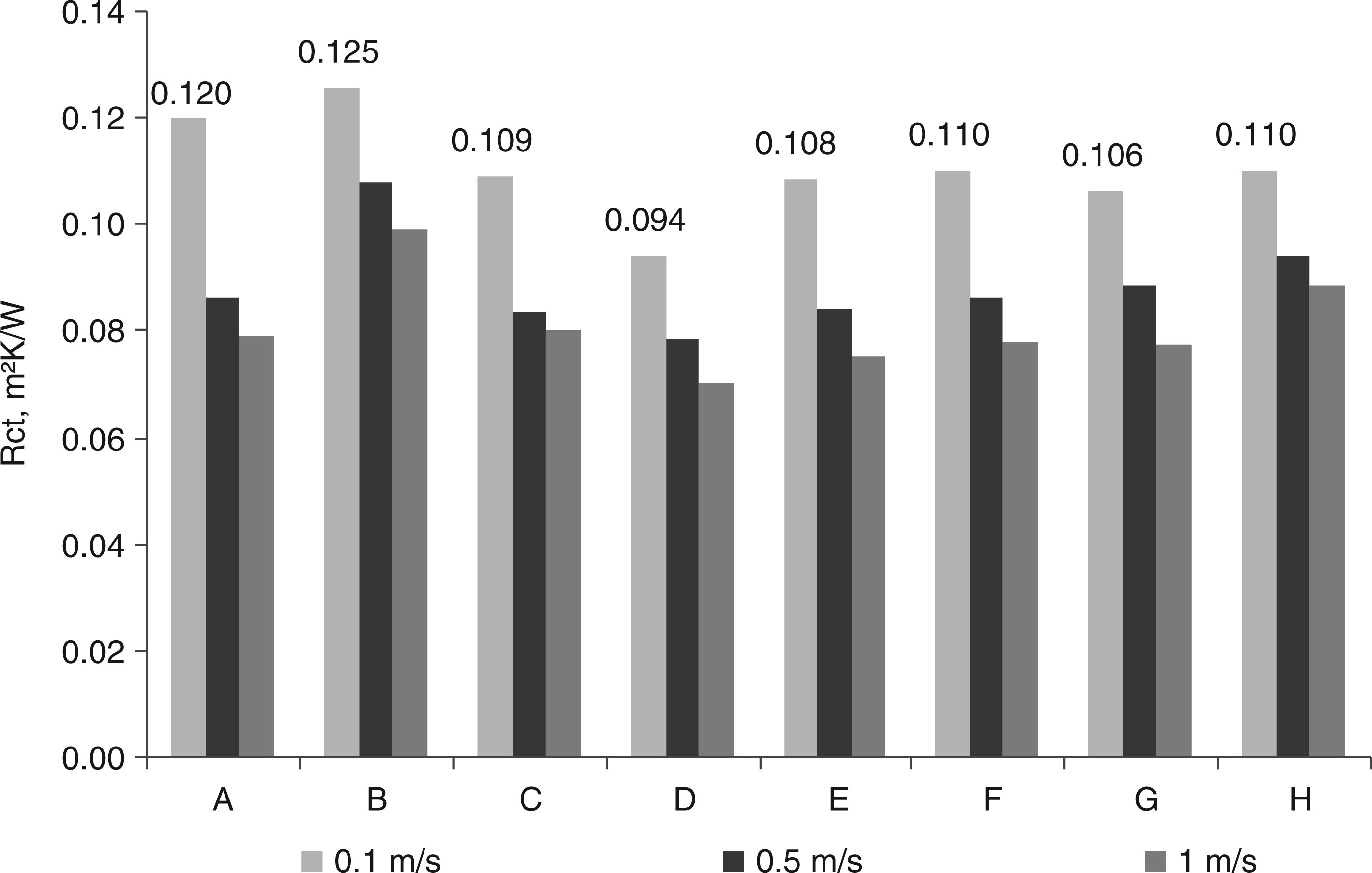
For textiles used in sportswear, a substantial decrease in Rct is observed with higher wind speed. The removal of the stagnant air layer on the fabric increases heat loss and water vapor transport.
In the present study, the major decrease in Rct already was observed up to 0.5 m s−1 wind speed; thus, water vapor transmission was studied at still air and 0.5 m s−1 wind speed.
Water vapor transmission rate
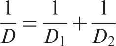
Gravimetrically, the WVTR of the bandages varied in the range of 231–341 g˙m−2˙h−1 (Table 1). Among the bandages tested, bandage H, regardless its total thickness of ∼1 cm, was characterized by the highest value of WVTR. The WVTR values were found to be in good correlation with the resistance to air (the value reversely proportional to the air permeability; Figure 5). The total resistance to air of the ensemble (1/D) was calculated as a sum of the resistances of each layer (1/Dx):
Bandage B had the lowest permeability for water vapors, which correlated with the extremely low air permeability of its padding layer. For porous materials with similar structure, high air permeability will support water vapor transmission; thus, for the given materials, a correlation between WVTR and air permeability could be expected.
Moisture gradient across the bandages
The humidity sensors were placed in a way that the humidity coming through the bandage was measured. Humidity of 100% R.H. measured on the membrane surface served as a criterion of steady-state water vapor streaming. However, saturation as a result of water vapor occlusion by the above-lying bandage cannot be excluded unless the humidity measured on the outer side on the respective bandage is also saturated or closed to saturation. Since moisture occlusion occurred in some cases, but not in others, it was considered that saturation measured above the membrane is due to the steady-state evaporation rate.

Correlation of water vapor transmission rate and calculated resistance to air of bandage systems A–H (mean and s.d. error bars).
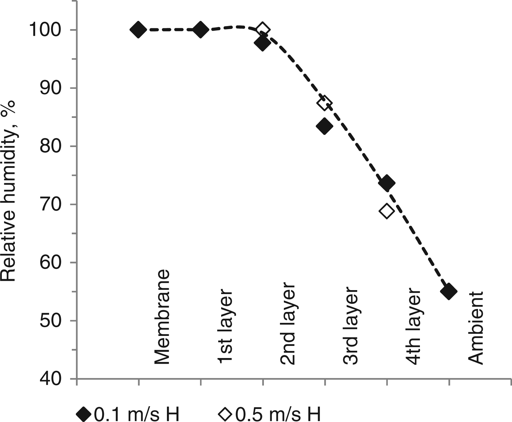
Comparison of various bandage systems revealed a noticeable difference between them in the ability to transmit water vapors. Several distinct profiles of moisture distribution in multilayer ensembles of compression bandages are shown in Figures 6 and 7. The dotted lines between the measurement points indicate an estimation of the moisture profile. The test was performed at still air and while applying an air stream of 0.5 m s−1. Bandage system A was characterized by good water vapor transmission performance, displaying high humidity on both padding and cohesive layers. Humidity measured on both layers of B was close to 80%. Noticeable moisture reduction occurred in the padding bandage, which was expected based on its very low air permeability. The contribution of the cohesive layer was not clear, due to the fact that the incoming humidity was already lower than 100%. Based on a small difference in humidity measured on the inner and outer side of the cohesive bandage, it can be assumed that it is sufficiently permeable to water vapor. Cohesive bandage B is highly permeable to air, while its permeability to water vapors is markedly reduced. Whether the decrease in humidity by 20% could be considered as moisture occlusion remains to be the subject of further study.
Relative humidity across representative cases of padding-cohesive systems B–D (four layers) established under quasi-stationary conditions of water vapor transport at wind speed 0 (filled symbol) and 0.5 m s−1 (hollow). Relative humidity across representative cases of bandage system H established under quasi-stationary conditions of water vapor transport at wind speed 0 (filled symbol) and 0.5 m s−1 (hollow).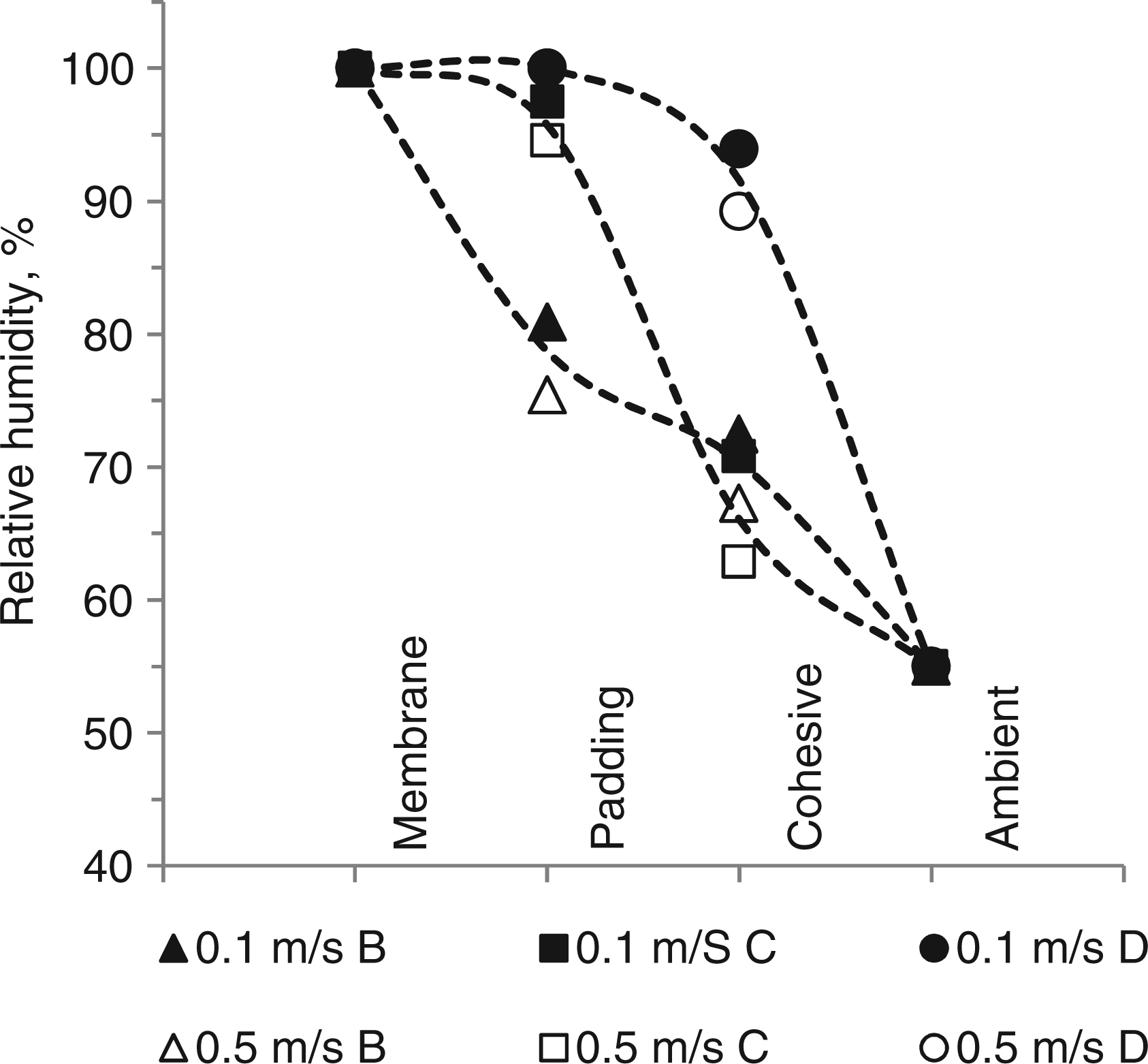
Bandage system C, regardless of its structural similarity to B, exhibited different behavior. Regardless of very similar values of air permeability, the padding bandage was highly permeable to water vapors and significant moisture hindrance occurred in the cohesive bandage.
The four-layer bandage H displayed very smooth moisture decrease across the layers, which is in good correlation with its air permeability. The layers in this ensemble are arranged in a way that every preceding layer has a permeability greater than or similar to the consequent one, which prevents the obstruction in multilayer system. As these experiments were performed at 26℃ plate temperature and 26℃ ambient temperature, no distinct effects of temperature gradients have to be considered.
Increase of moisture to the level of saturation will also support microbial growth in the respective part of the compression bandage. Such studies should be undertaken under real wear conditions, as human skin will serve as a main source for the release of microbes into the bandage. 27
The entire bandage ensemble H was characterized by the highest WVTR, 341 g˙m−2˙h−1, and humidity measured at the outer layer was about 70%. The high WVTR, 279 g˙m−2˙h−1, determined for bandage ensemble D and humidity measured across the layers above 90% suggest its good performance.
From the experimental setup, the Ret values were also calculated (Table 1). From a comparison of gravimetrical results for WVTR with the values for water evaporation determined from the electrical energy input, it was found that gravimetrical results yield a higher WVTR. Electrical energy consumption would indicate 30–50% of the values determined gravimetrically. These results are in accordance with the literature results on manikin tests, where the higher evaporation resistance was reported for the heat loss method. 18 Wang et al. 18 explained this finding with additional heat energy transfer from the environment, which contributes to the evaporation in the gravimetrical method; it is not registered in the heat loss method.
Moisture content
A high moisture sorption capacity will support climate buffering in the bandage structure by sorption/desorption of moisture during short periods of increased sweating.
Both approaches – WVTR and moisture gradient development – do not account for the amount of moisture absorbed and retained in the fabric upon streaming water vapor flux across the ensemble. Weighting the garments after the test is technically troublesome, as the water vapors diffuse very quickly, leading to tremendous uncertainties in the results. To get an approximate estimation of the amount of moisture retained in the bandages, we used a standard approach of moisture content determination. 26 The lowest moisture content, less than 1% of the fabric weight, was determined in padding bandages B, D, cohesive B, C and fourth layer H, whereas the highest moisture content, up to 9%, was measured for the first and third layers of H.
Conclusion
The limb model allows assessment of moisture gradient development in multilayer ensembles of bandages and, specifically, whether a certain layer could cause hindrance for water vapor transmission or not. The latter could be critical for multilayer ensembles, whose permeability varies markedly. Low water vapor permeability of the padding bandage could lead to moisture accumulation. Local R.H. near saturation could have a negative impact on the underlying skin, causing its maceration and possibly bacterial overgrowth. The occlusion in the cohesive bandage could lead to moisture condensation on its inner surface and subsequent liquid re-absorption by the padding layer. 28
While a plate model allows well-defined conditions for testing of thermal resistance, the limb model represents an approach that is more relevant to the application: Firstly, the direction of air streaming towards the testing specimen is parallel in the plate model, whereas in the limb model used it is streamed perpendicularly. Secondly, an increase in pore size due to stretching may increase permeability for air and water vapors, and decrease thermal resistance. 29 The tight arrangement of the layers due to stretching reduces the air gaps, which in a plain setup creates additional resistance for air and water vapors. In the presented model, the geometry is of nearly cylindrical shape; thus, the effect of shape on the thermal resistance and water vapor transmission is rather low. A higher influence of shape is expected at other parts of the body, for example, knee, elbow, or toes; however, then the complexity of the model and measurement device will increase considerably.
A good correlation was found between water vapor transmission and air permeability of the bandages tested. It could be expected that the fabric of relatively high air permeability will have a better performance in the water vapor transmission test, but the air permeability as the only indicator of breathability is not sufficient. It has to be kept in mind that air-permeability measurement implies streaming of the air through the fabric under relatively high pressure. In addition, air permeability of the bandages is tested in a single layer, whereas water vapor transmission is measured in a multilayer ensemble, where the layers are tightly fitted on top of each other.
A cylindrical model is advantageous over a plain layout not only for compression bandages and other types of wound dressings, but also for the garments that are worn under slight tension, as it allows better fit and contact pressure adjustment.21,22
The approach proposed in this study allows assessment of thermal resistance and water vapor permeability under simulated wear conditions. In addition, analysis of moisture gradient development across the entire ensemble can reveal the potential moisture occlusion in layers. The permissible level of moisture in bandages, which does not interfere with the sensation of comfort, remains to be validated in further clinical trials.
In the present experimental approach, the setup was designed to study thermal resistance and water vapor transmission through the textile assembly. Introduction of simulated liquid sweat release by controlled dosage is a part of ongoing research. Compared to the heat and vapor transfer, such experiments will also have to consider wicking and liquid distribution by capillary transport properties of three-dimensional structures.
Footnotes
Acknowledgements
The authors acknowledge the Versuchsanstalt-Textil and the HTL-Dornbirn for the use of their facilities.
Funding
This work was supported by the Austrian Research Promotion Agency (FFG K-PROJECT Nr. 820494) “Sports Textiles”.