
Abstract
In the present work, a study of two-step in situ chemical polymerization of polyaniline (PANI) on cotton fabric was undertaken by employing the jig-dyeing principle. The important reactant parameters, such as monomer concentration, oxidant/monomer ratio, protonic acid concentration and the duration of polymerization, were studied. The structural and morphological features of the resultant fabric were analyzed by Fourier transform infrared–attenuated total reflectance and scanning electron microscopy studies. The electrical conductivity was expressed as both bulk and surface properties. With the present experimental set up, a minimum electrical surface resistivity of about 103 ohm/square was achieved. The present investigation revealed that key parameters, such as protonic acid concentration, oxidant/monomer ratio and the duration of polymerization, are influential at lower monomer concentrations. Further, the treatment method and fabric construction appear to have a predominant role in the deposition, thereby affecting the resultant conductivity. The PANI-coated cotton fabrics thus produced are suitable in application areas of static protection and sensors for smart textiles. The described method of in situ polymerization has a potential for scaling up for bulk production.
Intrinsically conductive polymers (ICPs), unlike conventional polymers, are capable of conducting electricity owing to their typical structure, which comprises alternate single (sigma) and double (pi) bonds along the polymeric chains. 1 Most ICPs are not processable on their own, owing to the rigid chemical structure. Hence, conventional polymers in the form of solution, film and foam are rendered as substrates for inclusion of ICPs. 2 Furthermore, textile substrates, due to their high surface area, have been explored for deposition of prime ICPs such as polypyrrole, polyaniline (PANI) and polythiopene.3–9 Recent reports indicate that the ICP-coated textiles are evolving as strong contender against metal-based textiles in application areas of static and electrostatic discharge (ESD) protection, 5 microwave attenuation, 7 electromagnetic interference (EMI) shielding 8 and resistive heating textiles. 9 In addition, the growing interest in smart textiles/e-textiles 10 has all the more widened the scope of ICP-coated textiles due to their ability to retain textile characteristics to a remarkable extent.
Among the available ICPs, PANI has evoked tremendous interest among researchers due its ease in preparation, better atmospheric stability and promising conductivity characetrsitcs.11,12 The solubility of PANI in solvents such as N-methyl pyrrolidone (NMP) and concentrated sulfuric acid has been explored for wet spinning of PANI fibers. 13 Furthermore, incorporation of PANI in polymeric melts 14 and also as topical coatings on yarns/fabrics 15 are the other techniques of producing textile/PANI composites. However, the hazardous nature of solvents employed for spinning and coating operations is a cause of concern. Besides, melt-spun PANI/polymeric fibers are reported to possess poor electrical conductivity. 14 In view of the above techniques, the in situ chemical polymerization of PANI onto textile substrate is certainly a simple and ecological process for obtaining conductive textiles.
It is well known that the chemical route of synthesis of PANI involves oxidation of aqueous acidic monomer (aniline) solution with a suitable oxidizing agent (e.g. ammonium persulfate, APS). Similarly, for its synthesis onto textile substrates, the
Experimental details
Materials
Scoured, bleached and mercerized cotton fabric (130 g/m2) was procured from RSR Mohta Mills, Hinghanghat, India. Aniline (99%, analytical reagent (AR) grade) was used as the monomer. Ammonium persulfate (99%, AR grade) and hydrochloric acid (36%, AR grade) were used as the oxidant and protonic acid, respectively. Aniline was distilled fresh before polymerization and stored in refrigerated conditions.
Methods
Preparation of PANI-coated cotton fabrics
The schematic representation of the reaction set up of the jig-dyeing machine is shown in Figure 1. The fabric is wound onto a roller assembly equipped with two main rollers. The roller assembly is placed in the reaction bath after loading of the fabric. The winding/unwinding motion of the fabric was controlled with an electro-mechanical sensor for automatic reversal of the direction of rotation of the fabric; it ensures uninterrupted treatment of the fabric in the bath. The capacity of the reaction bath was 400 ml. In order to maintain the temperature of the reaction bath, the outer tank was interfaced with a temperature regulating system.
Jig-dyeing principle for in situ polymerization.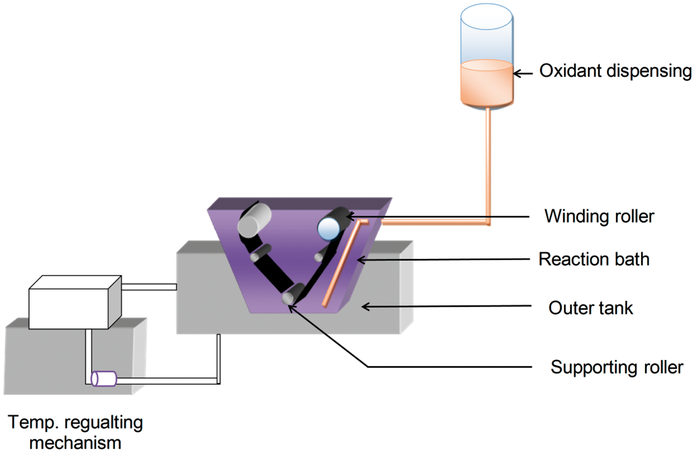
The cotton fabric samples were scoured to remove leftover impurities before proceeding to synthesis work. For polymerization, a fabric sample weighing 10 g (110 cm × 7 cm) was taken. It was first treated in the desired concentration of monomer (aniline + aqueous HCl) solution. The treatment with monomer solution was carried out for 1 h. After monomer treatment, a pre-cooled oxidant (ammonium peroxidisulfate + HCl) solution was dispensed in the reaction bath. The strength of HCl was retained at the same level for both the reactant solutions. Further, the reaction was continued for a specified duration (termed as the duration of polymerization). The temperature of the bath was maintained at 4 ± 1°C throughout the reaction for all the experiments.
After completion of the duration of polymerization, the in situ polymerized PANI cotton (CT-PANI) fabric was washed in dilute HCl to remove unreacted chemicals and oligomers. The fabric was then dried, conditioned and weighed.
Experimental design
Experimental plan
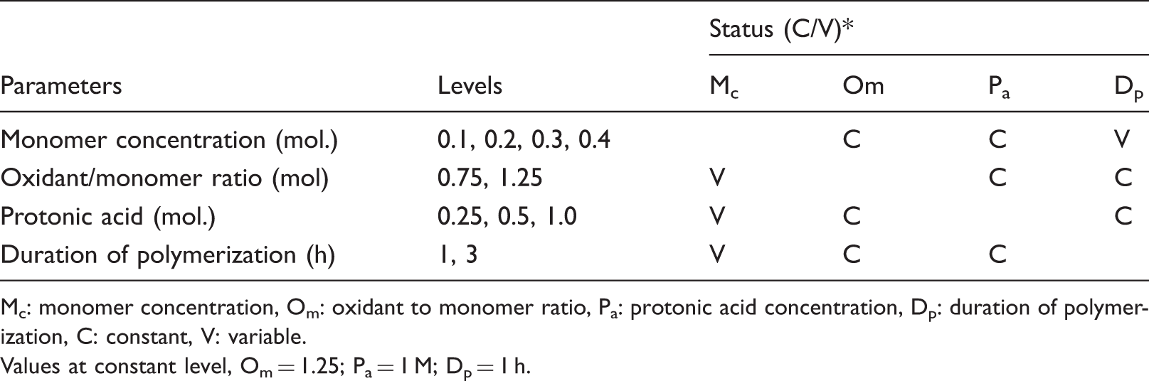
Mc: monomer concentration, Om: oxidant to monomer ratio, Pa: protonic acid concentration, Dp: duration of polymerization, C: constant, V: variable.
Values at constant level, Om = 1.25; Pa = 1 M; Dp = 1 h.
Characterization
Electrical surface resistivity
The electrical surface resistivity was measured as per the American Association of Textile Chemists and Colorists (AATCC) test method 76-2006 and expressed by the units ‘ohm/square’. For measurement purposes, the electrode assembly was based on two flat copper electrodes (30 mm × 20 mm) separated by a distance of 20 mm. A voltage source was connected to the electrodes through a multimeter. The measurement involved placing the electrode assembly over the fabric specimen (30 mm × 60 mm) with a weight of 5 kg. The electrical resistance values in each case were obtained by plotting the current versus voltage values (I/V curves):

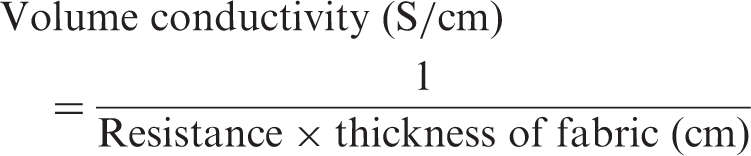
Volume conductivity
The volume conductivity was measured by placing a fabric sample (3 cm × 3 cm) between two pairs of spring-loaded rectangular copper electrodes. The inter-electrode distance of 1 cm was set for the measurements. The value of conductivity was calculated as follows:
The weight add-on of treated fabric due to the deposition of PANI was calculated by expressing the difference between the untreated and treated weight over the initial weight. The homopolymer precipitated in the bath was obtained by filtering the reaction solution through a sintered crucible. The filtrate obtained was washed with dilute HCl, dried and weighed as homopolymer. The surface morphology of fabrics was examined using scanning electron microscope from JEOL (Model JSM 5400). The chemical characteristics of fabrics were studied by Fourier transform infrared–attenuated total reflectance (FTIR-ATR) spectroscopy on a Perkin Elmer model 2000. The spectra were recorded by taking 50 scans at a resolution of 4 cm−1. The tensile strength of fabrics in the warp direction was measured, as per the American Society for Testing and Materials (ASTM) standard D 5035:11, with a raveled strip method.
Results and discussion
Deposition of PANI and surface morphology
The effect of the polymerization reaction on morphology changes in untreated and treated fabric is demonstrated in Figure 2.
Scanning electron microscopy images of untreated and treated cotton fabrics at various monomer concentrations: (a) untreated cotton fabric; (b) 0.1 M; (c) 0.3 M; (d) 0.4 M (duration of polymerization 3 h; oxidant/monomer ratio – 1.25).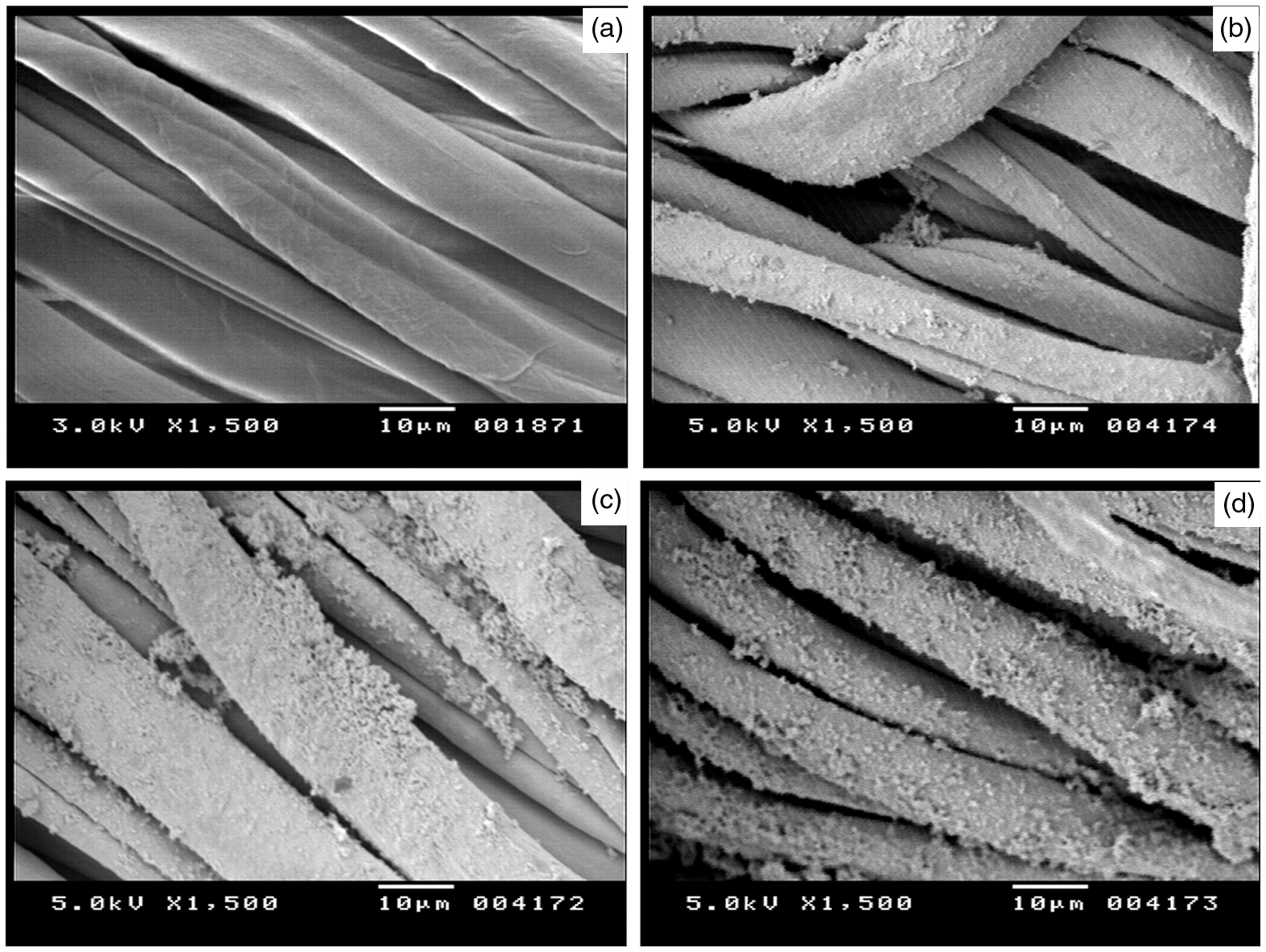
The scanning electron microscopy (SEM) image of untreated cotton (Figure 2(a)) shows a smooth and cylindrical surface of fibers. At 0.1 M monomer concentration, the PANI is deposited in the form of smooth and homogenous coatings on the surface of fibers (Figure 2(b)). With increasing monomer concentration to 0.3 M and 0.4 M, the deposition of polymer appears to be increasingly denser; the surge in growth of polymeric chains turns smoother coatings into granular dendrites. This haphazard growth might pose a problem of poor adhesion to the substrate, as it was noticed that a small proportion of polymer tends to be washed off during post-polymerization treatments.
Interaction with cotton fiber
According to earlier workers, the reaction of PANI with cotton is characterized by its diffusion into the fiber bulk. 23 In order to further study this interaction, we employed the SEM technique for analyzing a cross-sectional view of treated fibers. Being insulators, textile substrates are required to be coated with conducting material prior to SEM analysis, lest the accumulation of electrons leads to charge build up with time and discharge occurs after a certain limit of accumulation. 24 This process of charging/discharging can particularly occur in non-conducting areas; hence, it reflects in the form of bright streaks in SEM images.
By utilizing this fact, SEM analysis of individual PANI-coated cotton fibers was performed without gold-sputtering the sample during preparation. Figures 3(a) and (b) shows SEM images of the cross-section, as well as surface of fibers coated with PANI. It is worth noting that the innermost core of fiber appears bright, whereas the surface is free of such bright spots, which can be attributed to the conducting nature of surface-deposited PANI. It is also noteworthy that the adjacent area surrounding the fiber core is conspicuously free from such spots and shows an absence of charging phenomenon. This proves that during polymerization there is diffusion of PANI into the interior of the cotton fiber. The variable nature of core brightening could be attributed to the extent of diffusion, which could be a function of openness of the fiber structure and the treatment conditions.
Scanning electron microscopy images of treated cotton fiber showing diffusion of polyaniline.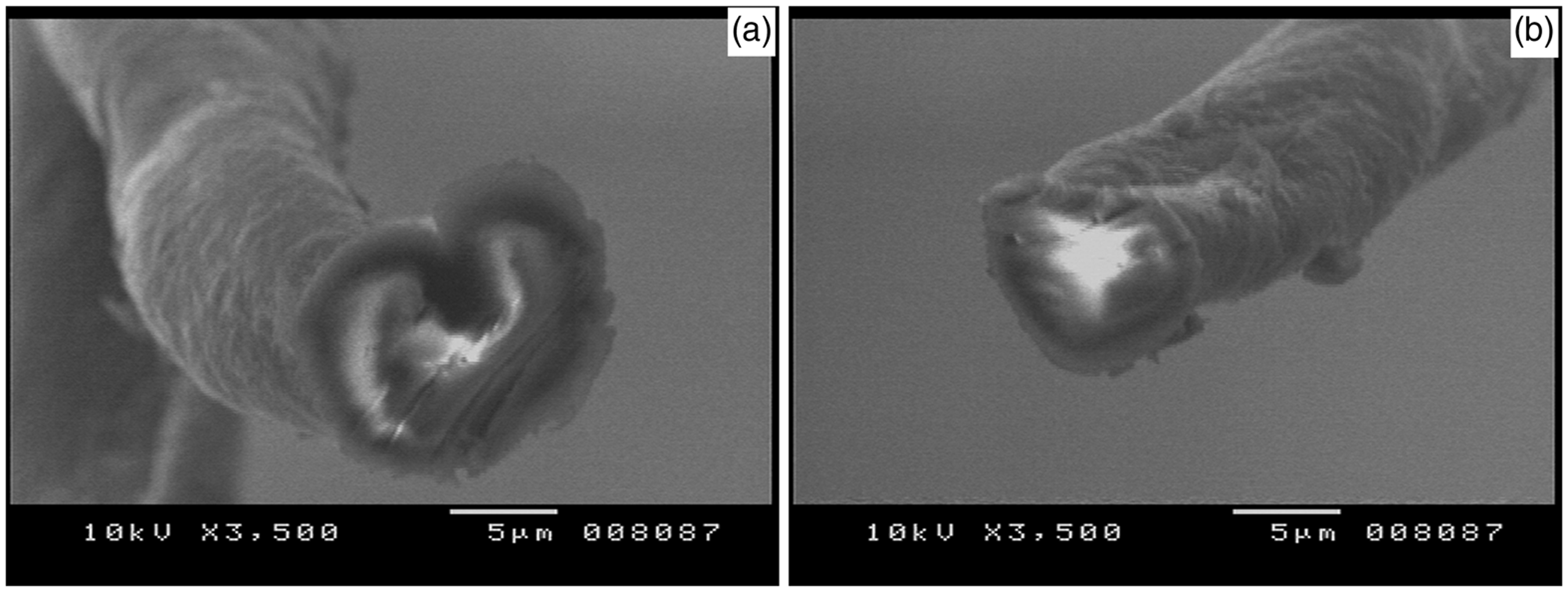
Electrical conductivity characteristics
The electrical conductivity of the treated fabric is a function of extent of PANI deposition on fabric substrate. In the present method, the treatment of fabric in monomer solution ensures adsorption of monomer molecules in the inter-fiber and inter-yarn spaces. After addition of oxidant solution, the color of the reaction solution and fabric immediately turn blue and then green as the reaction proceeds. This change in color can be attributed to the PANI polymerization mechanism, which is depicted in Figure 4. It is known that PANI exists in three oxidation states, each having unique optical, electric and electronic characetritics.12,26 These states are highly oxidized (pernigraniline), highly reduced (leuco emeraldine) and half oxidized-half reduced (emeraldine base). Amongst these, only emeraldine base is capable of electrical conduction after undergoing protonation. The chemical polymerization proceeds by formation of the protonated pernigraniline state (blue color) in the initial stage due to the intense oxidizing force.
27
The propagation state is marked by reduction of the pernigraniline form to protonated emeraldine salt (green color) by the monomer. It is worth noting that the in situ chemical polymerization of ICPs on textile substrates comprises two processes: deposition onto textile substrate and precipitation of its homopolymer in the reaction bath.
Chemical reactions during synthesis of polyaniline.
25
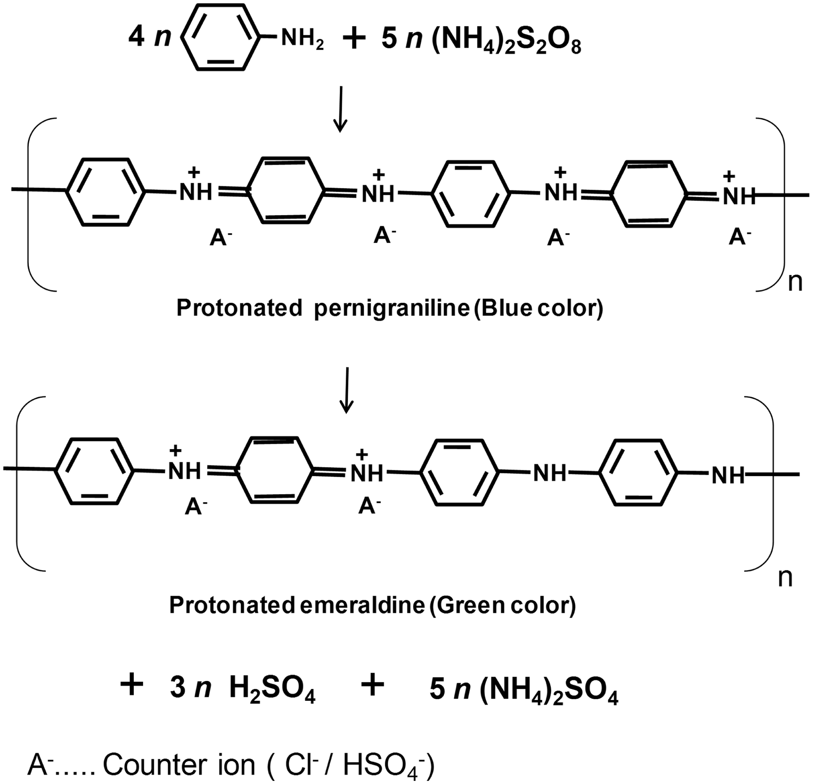
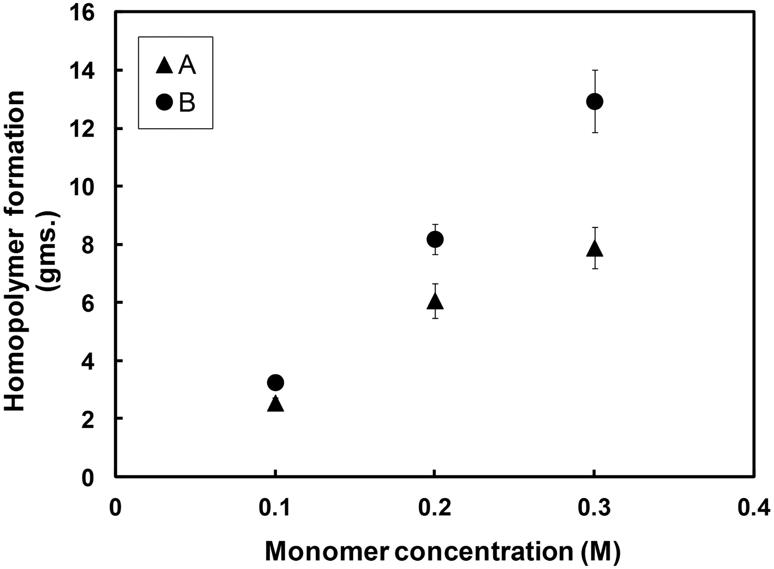
Figure 5 shows the behavior of surface resistivity at two different durations of polymerization carried out in 1 M HCl. The surface resistivity of untreated cotton fabric is in the range of 109–1010 ohm/square. The data in Figure 5 show that with an increase in monomer concentration, the surface resistivity diminished until 0.2 M, beyond which no significant decrease was observed. It can be seen from Figure 6 that a similar trend is depicted by volume conductivity measurements of fabric prepared at 1 h duration of polymerization. This decrease in the rate of reduction of surface resistivity with an increment in monomer concentration can be explained by studying the corresponding weight add-on values of treated fabrics (Figure 7) and the homopolymer precipitation pattern during polymerization (Figure 8).
Effect of monomer concentration on the surface resistivity of polyaniline cotton fabrics at the two durations of polymerization (1 and 3 h). Effect of monomer concentration on volume conductivity (duration of polymerization of 1 h). Relationship between weight add-on of fabrics and monomer concentration. Relationship between homopolymer formation and monomer concentration.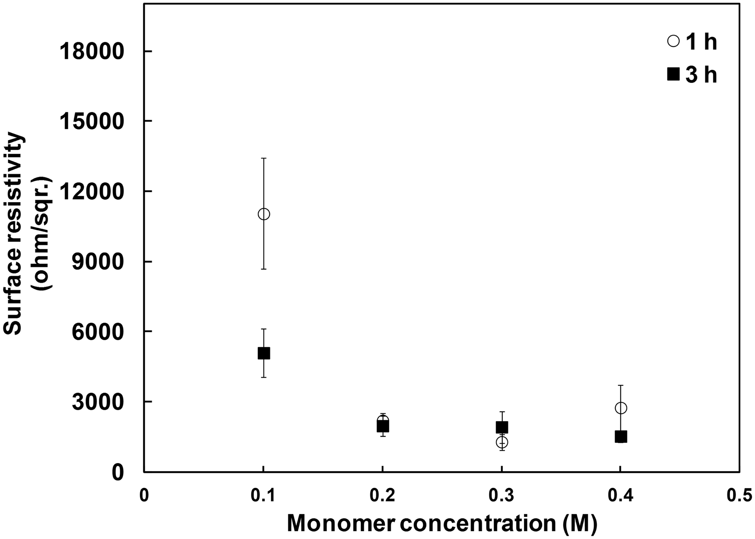

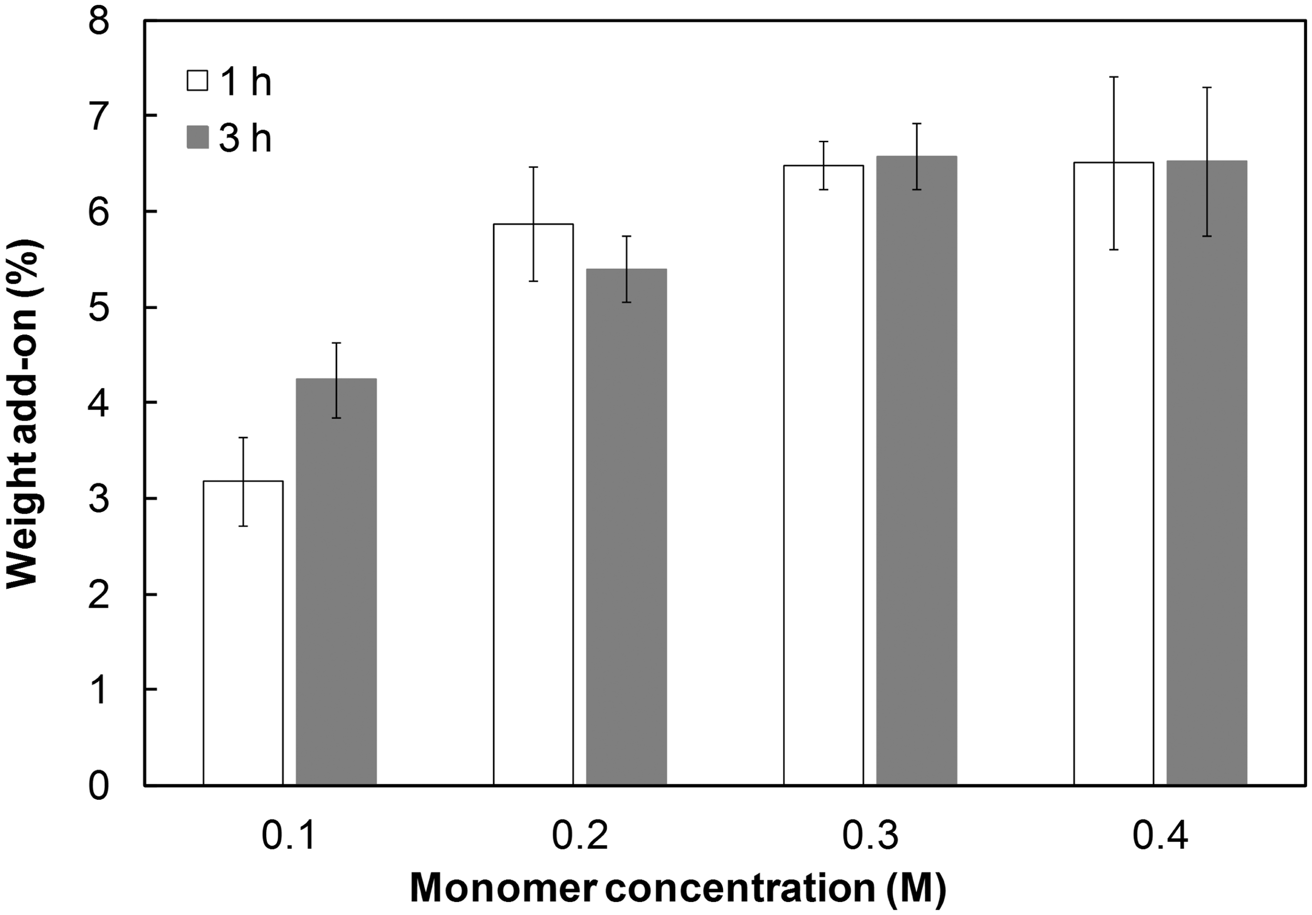
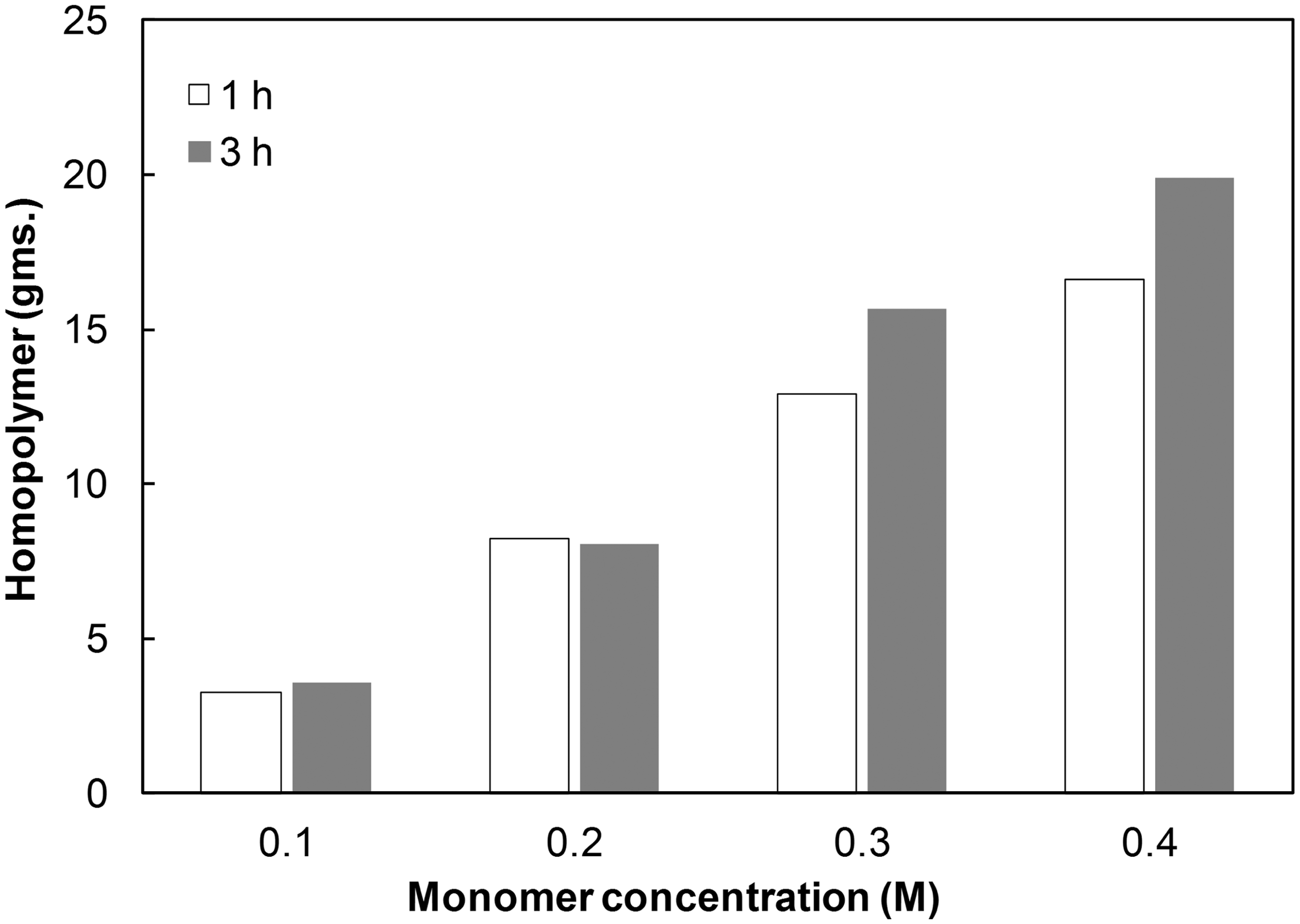
It can be noted that with an increase in monomer concentration, the weight add-on increase was observed up to 0.2 M. There was no significant improvement in weight uptake at higher concentrations. In contrast, the corresponding amount of homopolymer precipitated was increased substantially. From this we conclude that at lower concentrations, the polymerization predominantly involved deposition of PANI on the fabric surface. On the other hand, with increasing monomer concentration, the PANI homopolymer was preferentially formed in the reaction bath with a proportionate increase in its amount. In fact, we observed that at 0.4 M the amount of homopolymer formation reached such an extent that the reaction solution was turned into polymer slurry, hindering the smooth movement of fabric. This implies that the increase in concentration of monomer does not translate into enhanced deposition of polymer onto textile substrate. Furthermore, it also underscores a need for optimizing the PANI synthesis to achieve maximum deposition and minimum homopolymer precipitation.
The careful observation of Figure 5 also reveals that the effect of duration of polymerization on fabric surface resistivity was significant up to a monomer concentration of 0.1 M. It appears that the low concentration of reactants apparently resulted in the slower reaction rate. 28 Thus, at lower monomer concentrations, extending the duration from 1 to 3 h has compensated the slowdown and thereby yielded lower surface resistivity. This is in good accordance with the work of Oh et al. 20
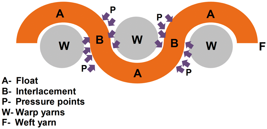
With the present set of reaction parameters, the surface resistivity values of treated fabric obtained are higher than expectation, reflecting low level of electrical conductivity. In our opinion, there are two reasons for this behavior. Firstly, although the jig-dyeing principle involves continuous movement of fabric, its interaction with the reaction bath is momentary at any given time; this is different to other wet-processing techniques (e.g. jet dyeing, winch dyeing) where a certain amount of substrate stays in the reaction bath for a considerable time, providing opportunity for thorough saturation with reaction solution. In our opinion, this paucity of interaction in the jig principle may play an insignificant part in textile dyeing but it seems to be more relevant for ICP synthesis on fabrics. It reflects on the need for enhancement of interaction of substrate/reaction solution for the deposition of PANI by prolonging the treatment durations. Secondly, a peculiar diffusion and deposition pattern on the constituent yarns of the treated cotton fabric was observed. As shown in SEM images (Figures 9(x) and (y)), the deposition of PANI depicts two distinct areas occurring alternately on the yarn surfaces, which are present as floats and interlacements in the fabric weave structure. The PANI deposited on the float regions (A) is substantially higher than that of the interlacement regions (B). Further, there was appreciable visible difference in the two regions in any yarn pulled out from the fabric; the float regions appear densely greener in comparison to interlacement regions, which are pale green. It is worth noting that the treated substrate fabric was a plain woven cotton. In plain weave, warp and weft yarns undergo interlacement at every contact point, offering a tighter construction as compared to some of the other weaves, such as twill and sateen. Figure 10 is a schematic representation of a yarn path in a plain-weave, depicting float and interlacement regions. The pressure exerted on the fibers in the interlacement points generates tight spots and thereby might restrict the accessibility for diffusion. Since float regions are unconstrained by such forces, the fibers in this region tend to be free from any hindrance for diffusion/deposition. As it is a plain weave, the situation is equally applicable to warp and weft yarns. Furthermore, the same observation was noted for all the variable reactant concentrations and reaction parameters.
Scanning electron microscopy images of yarn pulled out from the treated fabric showing varying degrees of deposition. Schematic representation of yarn in a plain weave fabric.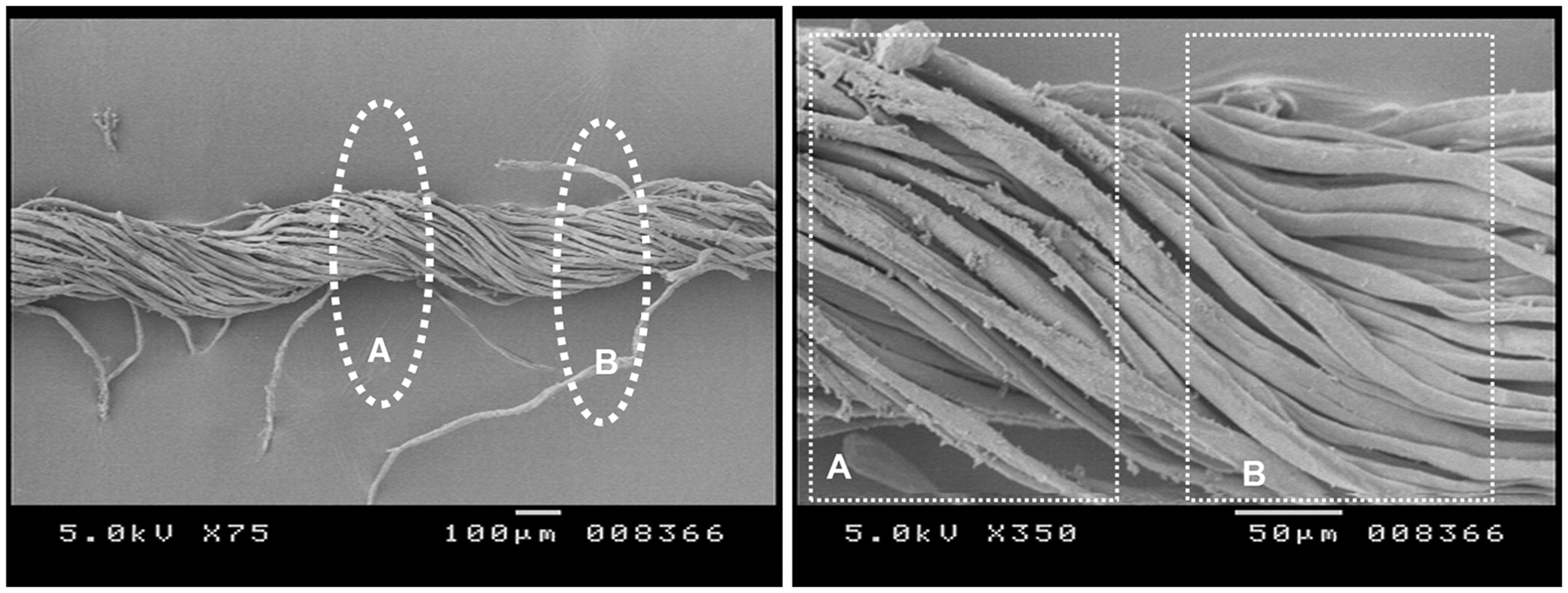
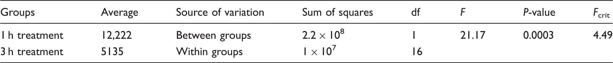
Analysis of variance table for variation in duration of monomer treatment
FTIR-ATR characterization
Figure 11 shows the FTIR-ATR spectra of untreated cotton fabric and CT-PANI fabric prepared at 0.1 M aniline concentration. The untreated cotton (a) shows a broad peak centered at 3313 cm−1 corresponding to O-H stretching. Similarly, the peaks at 1370, 1339 and 1317 can be attributed to CH bending, OH in-plane bending and CH wagging of the cellulose molecule, respectively.
29
The characteristic peaks related to PANI observed in the treated fabric (b) affirm its incorporation onto cotton substrate.26,30 For instance, the peaks at 1560 and 1470 cm−1 correspond to quinonoid and benzenoid ring stretching, respectively. The equal intensity of the quinonoid and benzenoid peaks, as well as the presence of a 1232 cm−1 peak (assigned to C-N+ stretching vibration), corroborates the existence of the protonated emeraldine salt.
26
It is worth noting that the intensity of the characteristic cellulose ring band (1000–1050 cm−1) has diminished in the spectra of treated fabric. This can be attributed to the characteristic depth (0.5–5 microns) of penetration of IR rays in ATR technique, thereby diminishing the peaks related to cotton with increased polymeric deposition.
Fourier transform infrared–attenuated total reflectance chracterization of (a) untreated cotton fabric and (b) polyaniline cotton fabrics prepared at monomer concentrations of 0.1 M (duration of polymerization: 1 h, oxidant/monomer ratio: 1.25).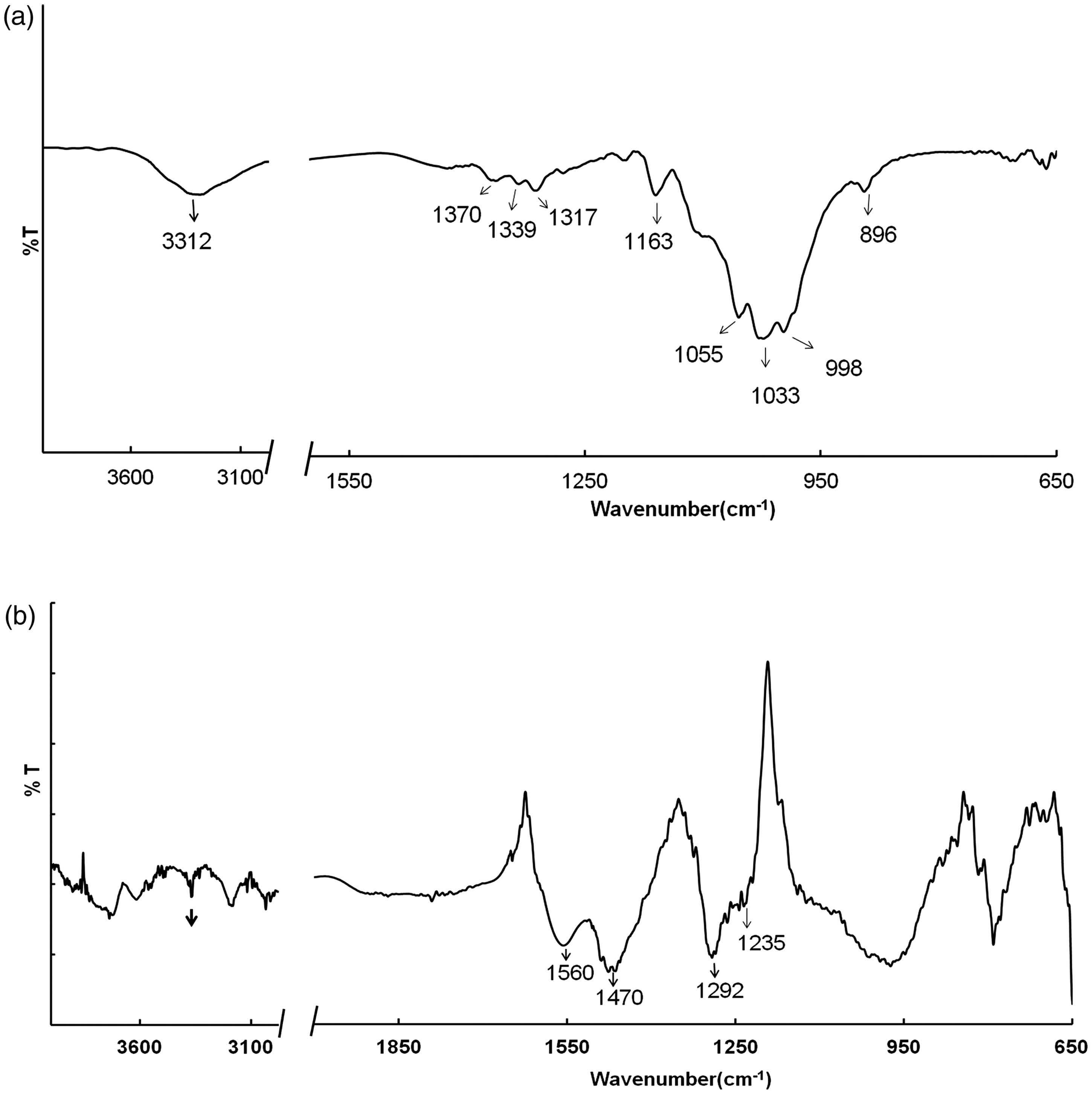
Studies on reactant concentration
Oxidant/monomer ratio
In the present study, analysis of the effect of oxidant/monomer (o/m) ratio on the fabric surface resistivity was carried out at two levels, that is, 0.75 and 1.25. Figure 12 illustrates the relationship between surface resistivity and monomer concentration at the aforementioned o/m ratios. It can be seen that for 0.1 M monomer concentration, the surface resistivity at o/m ratio 1.25 is about one third as compared to that obtained at 0.75 o/m ratio. With an increase in the concentration of the monomer (i.e. 0.2 M), the difference in surface resistivity was diminished to a remarkable extent. Furthermore, at 0.3 M, the difference was observed to be statistically not significant. This trend can be correlated with the homopolymer precipitated in the bath during corresponding experiments (Figure 13). The homopolymer formation exhibits the exact opposite trend to that of the surface resistivity. Here, the amount of polymer precipitated in the bath increases at an o/m ratio of 1.25 rather than that at 0.75, widening the gap with each increasing monomer concentration.
Effect of monomer concentration on the fabric surface resistivity at two oxidant/monomer ratios: (A) 0.75; (B) 1.25 (duration of polymerization: 1 h). Effect of monomer concentration on homopolymer precipitation in the reaction bath at the studied o/m ratios: (A) o/m 0.75; (B) o/m 1.25.
It can be noted that with APS as an oxidant, the stoichiometry and the related experimental reports28,30 suggest an o/m ratio of 1.25 is optimum for achieving a higher yield of homopolymer PANI. Nevertheless, Cao et al. 31 suggested that the o/m ratio has a minor effect on electrical conductivity characteristics. In addition, for textile-related studies, the o/m ratio seems to be governed as much by the reaction parameters as by the method of preparation; for example, Oh et al. 20 reported an optimum o/m ratio of 1 for PANI-nylon 6 composite fabrics prepared by the DBMP process. Li et al. 21 reported 1.8 as an optimum o/m ratio for PANI deposition on cotton fabrics by using the padding method. Our results principally suggest that with decreasing o/m ratio, a 30–40% reduction in homopolymer precipitation is achievable without sacrificing the electrical conductivity of resultant fabrics, especially for high monomer concentrations (>0.1 M). A similar observation has been reported for the o/m ratio in the case of homopolymer synthesis. 28
Protonic acid concentration
pH values of the reaction solutions
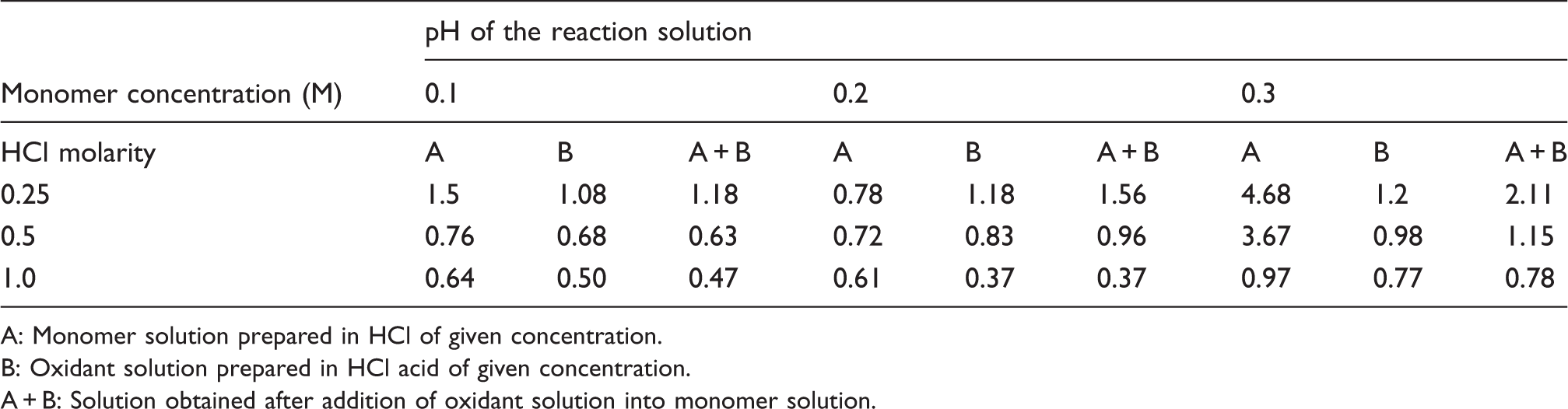
A: Monomer solution prepared in HCl of given concentration.
B: Oxidant solution prepared in HCl acid of given concentration.
A + B: Solution obtained after addition of oxidant solution into monomer solution.
Figure 14 shows the behavior of surface resistivity of fabrics with monomer concentration at the three HCl concentrations. It can be seen that at a concentration of 0.1 M monomer, 0.25 M HCl has yielded minimum surface resistivity. This can be explained by correlating the polymerization mechanism and its dependence on pH of the reaction medium. A careful study of Table 3 reveals that for 0.1 M monomer concentration and 0.25 M HCl, the pH values of all three reactant solutions (monomer, oxidant and mixture) are higher, indicating lower acidity as compared to 0.5 and 1.0 M HCl. The propagation of PANI polymerization takes place by abstraction of hydrogen atoms from aniline. It has been reported that higher acidity could result in a disproportionately high protonation of aniline monomers restricting the release of protons, thereby slowing down the polymer growth.
22
This appears to be responsible for higher surface resistivity of fabrics treated at higher HCl concentrations for 0.1 M monomer. Interestingly, as the monomer concentration was increased (i.e. 0.2 and 0.3 M), no substantial difference between surface resistivity values was observed for all three concentrations of protonic acid. It is worth noting that the pH values “(A+B)” were recorded immediately after mixing the oxidant solution in the monomer solution. However, the pH of the mixed solution continuously decreases due to the release of protons and the formation of sulfuric acid as a byproduct during synthesis. Hence, chemical synthesis of PANI is often mentioned in literature as the “falling pH method”. The same phenomenon appears to have contributed toward providing the required acidic environment, especially in the case of a combination of high monomer concentration prepared in weak HCl (e.g. 0.3 M monomer and 0.25 M HCl).
Effect of protonic acid concentration on the fabric surface resistivity.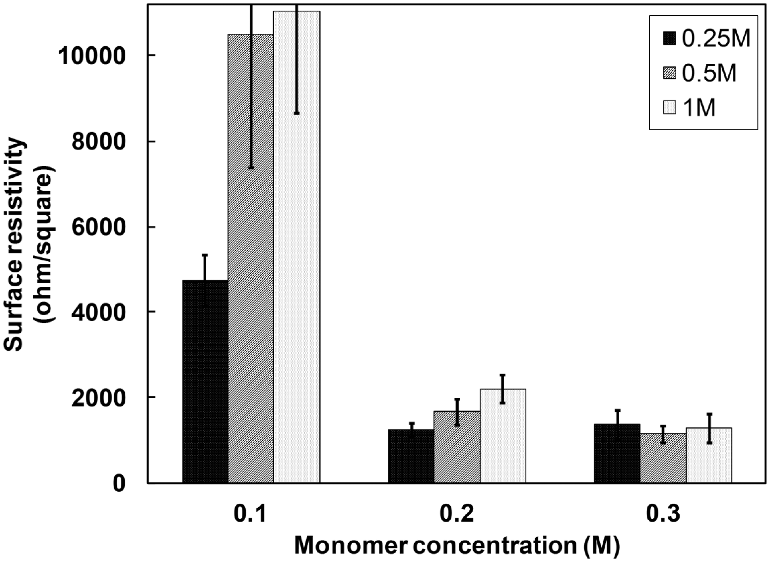
Effect on tensile strength
Figure 15 shows the comparison of tensile strength of untreated cotton fabric against fabrics prepared at various monomer concentrations. There was no impairment of the strength of the treated fabrics even for 3 h of polymerization. The absence of hydrolytic degradation of cotton cellulose in the presence of HCl can be plausibly attributed to the use of low temperature for the reaction, as the degradation process in cold conditions is very slow in nature.
32
It can be deduced that the deposition of PANI on cotton fabric does not alter the strength characteristics. However, the tear resistance of fabrics – another important criterion of mechanical strength – has not been studied in the present study, as the treated fabrics failed to meet the sample size requirements of the prevalent tear-strength standards.
Tensile strength of untreated cotton fabric and fabrics prepared at various monomer concentrations at two durations of polymerization: 1 h (A) and 3 h (B).
Conclusions
The in situ polymerization of PANI on cotton fabrics performed in the present work has proved the suitability of the jig-dyeing principle, as well as established the interrelation between reactant parameters and conductivity characteristics. The dynamic synthesis ensured uniform deposition of the polymer due to constant exchange of reaction solution with fabric substrate. The minimum surface resistivity of the treated fabrics obtained was 103 ohm/square. The increase in monomer concentration beyond a certain concentration (0.2 M in the present case) stimulates formation of the homopolymer, which appears to be detrimental for achieving superior conductivity characteristics. The intermittent contact between the fabric and the polymerization bath, as well as the tighter weave construction, was responsible for the differential deposition of polymer on constituent yarns. The FTIR-ATR characteristics confirmed the deposition of the conductive form of PANI. Overall, parameters such as protonic acid concentration, o/m ratio and duration of polymerization were found to have greater influence at lower monomer concentration. The tensile strength of treated fabrics was retained even after PANI coating. Except for applications where high conductivity is required, the surface resistivity range obtained can be effectively employed in certain applications, for example, static dissipation and smart textiles. Future work can be focused on studying the conductivity characteristics in the context of weave pattern and construction parameters of fabric substrates.
Footnotes
Acknowledgment
We are grateful to Dr AN Desai, Director, and BTRA for constant support and encouragement during this work. The technical inputs of Dr NV Bhat and Dr GS Nadiger are highly appreciated. The authors are also thankful to Mr Walunj, scientific officer BTRA, for his immense help in SEM analysis. We are grateful to anonymous reviewers for their helpful suggestions.
Funding
This work was supported by the Ministry of Textiles, Government of India (grant number-06/17/2009-CT-I).