
Abstract
The following paper presents the solution to the problem of searching the best shape – structural form of the bottoms and optimal dimensions of the main cylinder of the carding machine with consideration to the criterion of minimal deflection amplitude of its shell. The Finite Element Method has been applied for searching the optimal solution. As a result of the performed analyses, reduction of deflection amplitude at approximately 77% has been obtained. The determined optimal structural form and dimensions of the cylinder enable application of a new textile technology – microfibre carding as well as improvement in the quality of traditional carding technology of woolen and wool-like fibres performed on roller carding machine. The final stage of the work has been to determine the influence of manufacturing tolerances of the cylinder and metallic card wire on the amplitude of the main cylinder deflection.
Introduction
Carding is one of the most important textile technological processes, whose aim is intermixing loose fibers and removing impurities and short fibers, as well as straightening and parallel arrangement of the remaining fibers. Woolen and wool-like fibers are reworked with the use of roller carding machines.
1
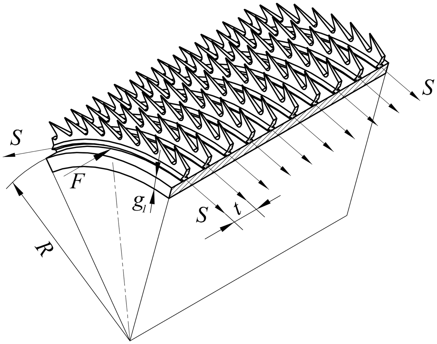
Its scheme in Figure 1. If the carding machine is the last machine in the carding set, the oscillating blade (doffer comb) combs and condenses the fibers after carding and the web is formed. On the surface of the main cylinder (the swift), doffer and working rollers (workers and strippers) there are teeth of a saw metallic wire (Figure 2) or card clothing needles, which are reeled coil to coil with appropriate tension.
Carding machine scheme. Tension forces acting on the metallic card wire coils.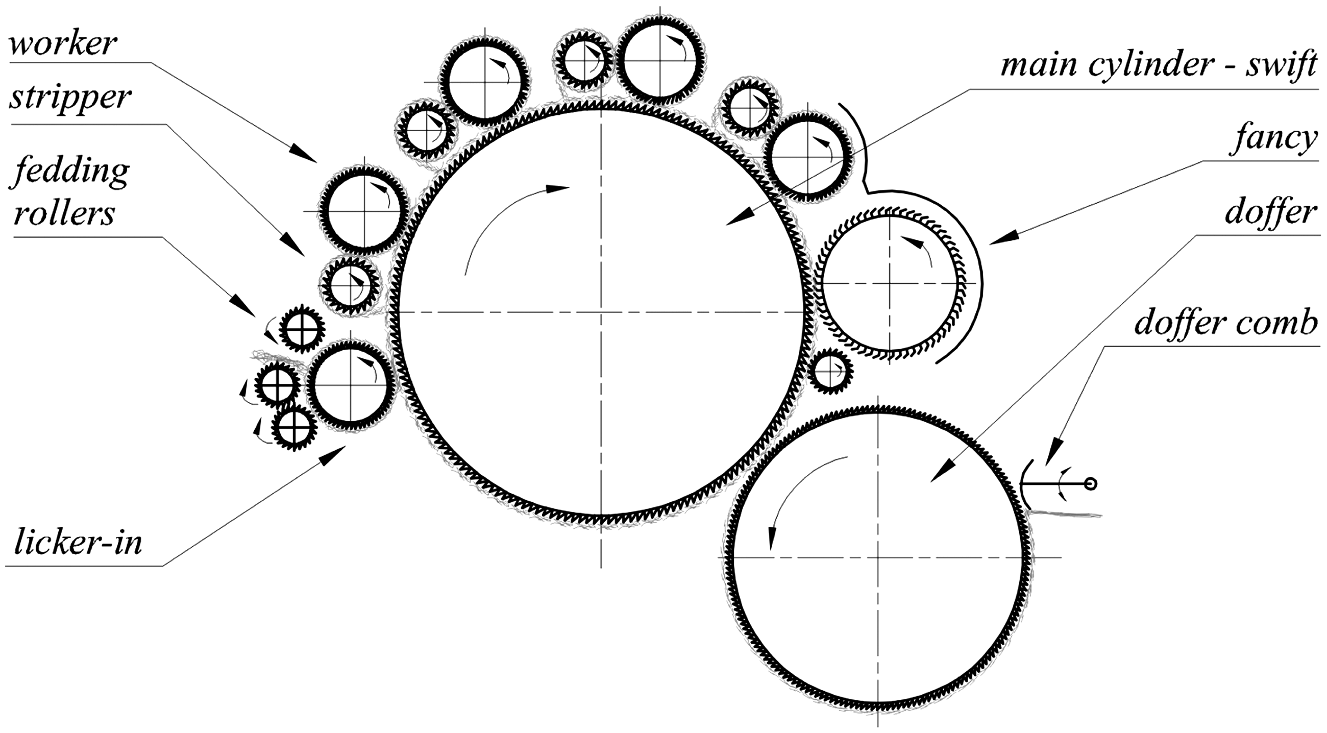
Carding quality depends to a large degree on the height and shape of the gap between the pairs of swift and worker as well as the swift and doffer. During carding of thin fibers, the gap between the last worker and the main cylinder is between 0.3 and 0.15 mm. Considering desirable uniformity of the web, its shape should be close to the shape of a rectangle. Taking into account the durability of the metallic card wire teeth (the hardness of a tooth decreases from top to base), the cylinder should not be ground after the wire is reeled. It is worth adding that the textile industry more frequently uses super-thin fibers (microfibers). Their carding requires smaller distances between working rollers and the swift and between the swift and the doffer than those mentioned above. The cylinder should be designed so that after reeling the metallic card wire on it at tension, the deflection of its shell does not exceed several hundredths of a millimeter. Taking into account its dimensions (diameter × length: swift
The cylinders (swift and doffer) of modern carding machines are almost solely welded constructions (Figure 3). They consist of a shell reeled of metal sheet welded along its edges, flat bottoms with hubs stiffened with ribs, a shaft and reinforcement rings. Such constructions are used by leading carding machine manufacturers and particular solutions are different as to the bottom and reinforcement rings construction.
Cylinder construction.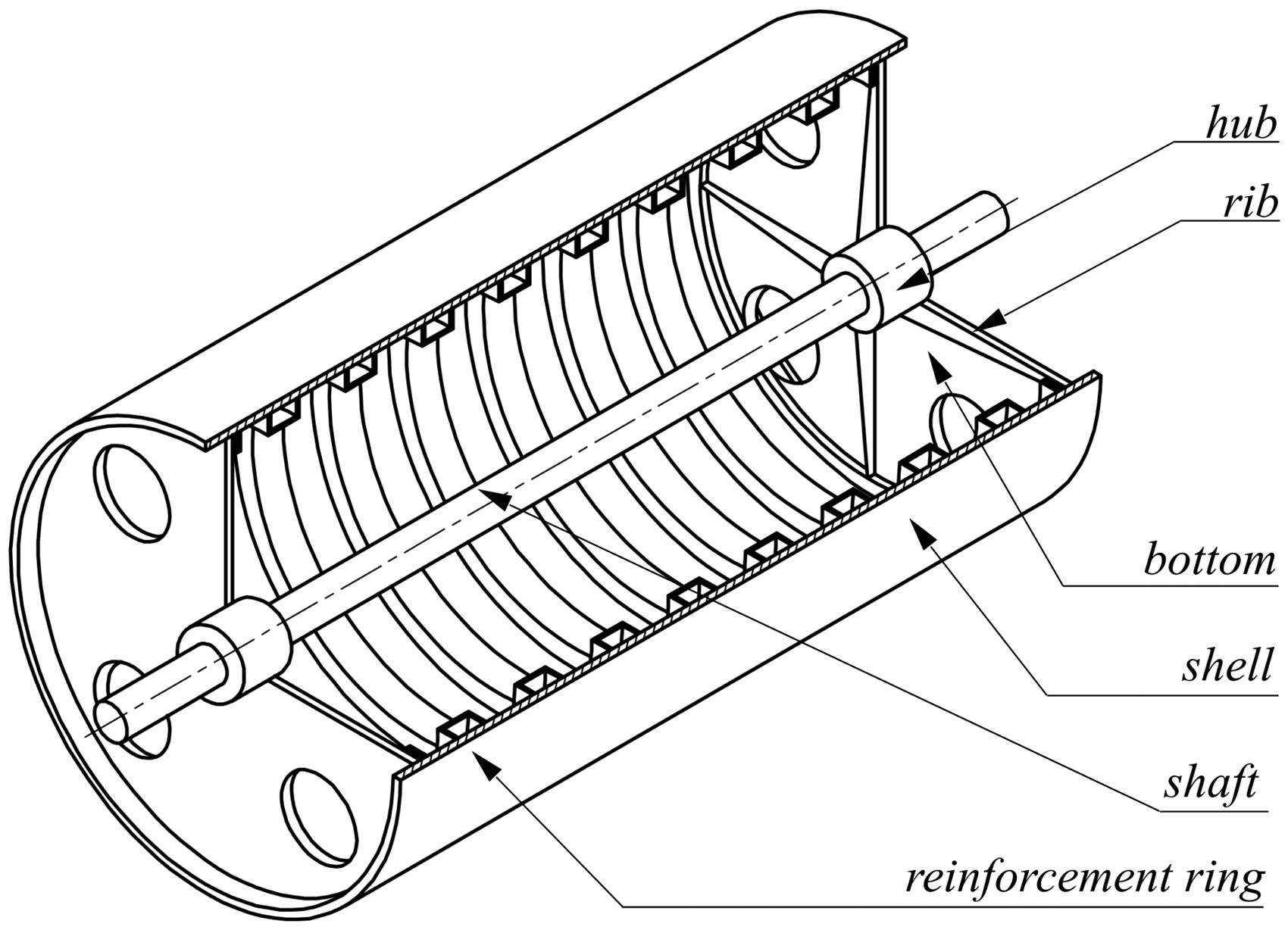
Loads acting on the main cylinder of the carding machine
The loads acting on the cylinder result from:
the influence of fibers on the teeth of card wire during the carding process; the forces are small and are omitted when calculating deflection of the cylinder shell; the construction dead weight and the centrifugal force; their influence on the cylinder deflection may also be neglected due to the large stiffness of the shell and reinforcement rings, as well as the small rotational speed of the cylinder (circa 100–200 rpm); taking into account the dead weight and the centrifugal force makes a difference in deflection of no more than 3%; reeling at tension of the metallic card wire.
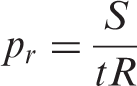
Reeling at tension S and the reeling pitch t of the card wire on the cylinder with the radius R (Figure 2) causes pressure on the cylinder shell directed radially inward with the value of
As shown by Stadnicki and Wróbel,
2
taking into account only radial pressure

Stadnicki and Wróbel
2
proved that taking into account both the pressure
Optimization of cylinder dimensions – summary of the results of previous work
The deflection
The deflection amplitude is then equal to

Therefore, an obvious conclusion can be drawn. Decreasing the deflection amplitude of the cylinder with a given radius and with a given load applied requires increasing the wall thickness g1. However, the increase in thickness g1 increases the cost and the mass of the cylinder. Moreover, it makes the mass moment of inertia larger, which in turn causes problems with starting the machine and imposes the necessity of using special brakes for stopping the cylinder in the required time in the case of a breakdown. Therefore, in the 1990s carding machines were equipped with cylinders with internal ring-like reinforcements (see Figure 3). The rings stiffen the shell without significantly increasing its mass moment of inertia.
The optimization task of the dimensions of a cylinder with reinforcement rings was the object of Stadnicki’s
4
analysis. Decision variables of the task were the shell thickness and the ring cross-section area. Flexibility of the bottoms (hubs with wheel arms and circumferential rings) was taken into account; however, the shape and dimensions of the bottoms were not optimized. The task was solved by minimizing the deflection amplitude while at the same time keeping the mass of the cylinder without rings and minimizing the mass, keeping the permissible deflection amplitude. The task was solved for a different number of rings, determining their optimal number. The continuous calculation model was used to find an analytical solution of the problem of cylinder shell deflection under the influence of only radial pressure The deflection line of the cylinder shell: A – without rings, B – with reinforcement rings.
Optimization of cylinder and bottoms
In order to determine the optimal structural form of the cylinder construction parametric, a finite element method (FEM) model was prepared and an appropriate optimization task was formulated and solved.
FEM model of the cylinder
The discrete calculation model of the cylinder (Figure 5(a)) with a flat bottom (see Figure 3) was made in the ANSYS package
5
using Shell 63 elements (shell and bottom and its ribs) and Beam 188 elements (rings and shaft). Shell 63 is a four-node shell element with six degrees of freedom in each node – three translations and three rotations – which takes into account the membrane and bending state of the shell. Beam 188 is a two-node beam element that is consistent with Timoshenko beam theory. Hinged support on the right-hand side (the side where the belt transmission driving the cylinder is placed) and the roller support on the left-hand side were applied in the nodes. Due to the fact that in real constructions the bottom’s circumference is permanently fixed to the shell, the shell nodes that lie in the bottom plane and the adjacent nodes on the left- and right-hand side were coupled with the nodes on the circumference of the bottom, ensuring compatibility of the node values (translations and rotations). Axisymmetrical radial surface pressure Discrete cylinder model: a) FEM model-fragment, b) loads scheme.
All analyses were performed with the use of input files for the ANSYS program. Using the ANSYS Parametric Design Language, a parametric FEM model of the analyzed construction was written and the optimization task formulated. It is worth emphasizing that the input file prepared in this way enables fast analysis and optimization of cylinder constructions for various working widths and structural forms of construction (e.g. with any number of reinforcement rings).
Calculation results
As a result of the discrete model analysis of the optimal cylinder with a flat bottom, a graph of the deflection line was obtained (Figure 6). The value of the deflection amplitude is The scheme of the optimal cylinder and the deflection line with flat bottoms.
The analysis of the deflection line of the cylinder shell with optimal thickness with rings and flat bottoms with optimal dimensions (Figure 6) proves that a further decrease of the deflection amplitude requires applying special bottoms welded with steel plates (Figure 7). The bottoms should be flexible in the axial and radial directions and, at the same time, it is necessary to ensure the required stiffness of the whole cylinder both during carding and during its manufacturing (grinding the surface with a disk-type grinding wheel before reeling the metallic card wire).
Changed construction of the bottom with conical ring.
In order to examine the influence of structural form of the bottoms on the value of deflection amplitude, a series of numerical tests for various configurations of cylinder constructions were performed. Discrete models for cylinders that have bottoms with a conical ring were developed in a similar way to that for cylinders with flat bottoms.
The two models, which are most interesting from the point of view of the performed analyses, are presented below. In the case of configuration I (Figure 8), one may assume that the bottoms bending under pressure The scheme of the cylinder and the deflection line for configuration I. The scheme of the cylinder and the deflection line for configuration II.

Optimization task
In order to determine optimal dimensions of the cylinder, as presented in Figure 9, the following optimization task was solved:
the dimensions shown in Figure 10 were accepted as decision variables: the deflection amplitude of cylinder the feasible set of the solution (constructional variants) is delimited by the following conditions:
○ ○ Denotations of decision variables in optimization task.
Moreover, appropriate variation ranges for decision variables were introduced for the task. The ranges resulted from technological conditions, such as difficulties in the proper manufacturing of the shell by reeling a flat sheet of steel with a width of over 14 mm, as well as boundary dimensions of the section of reinforcement rings resulting from the technology of reeling the ring and the availability of the semi-finished product.
In order to solve the task, a Polak–Ribery conjugate gradient method has been used together with the interior penalty method 8 implemented in the ANSYS package. 5
As a result of solving the above-mentioned optimization task, optimal values of dimensions Deflection lines of the cylinder shell before and after optimization.
The influence of accuracy of cylinder manufacturing on its shell deflection
The optimal structural form (bottoms) and optimal cylinder dimensions were determined assuming zero manufacturing tolerance of all cylinder dimensions. Industrial practice and experimental studies
2
show that the shell deflection is mainly influenced by:
deviation of the wall thickness of the shell, deviations of the shell shape, which are measured by the cylinder radial run-out around its axis of rotation.
Figures 12 and 13 present in unfold form (in cylindrical coordinates – see Figure 5) the thickness of the cylinder wall and the deviation of radial run-out measured for the real cylinder of the carding machine.
6
As we can see, the scatter of the real wall thickness of the cylinder is significant. It ranges from 10.4 to 15.8 mm and constitutes 43% of the nominal thickness The unfold of the real wall thickness of a sample cylinder. The unfold of radial run-out deviation a sample cylinder.

Figure 14 shows the unfold of the cylinder surface after reeling the saw wire for the ideal cylinder (Figure 14(a)) and the real cylinder (Figure 14(b)).
The unfold of the cylinder surface after reeling the saw wire: a) – ideal cylinder, b) – real cylinder.
Conclusion
The following article presents work aiming at improving the quality of carding machine working cylinders. The methodology of choice of the structural form and cylinder dimensions was developed. The result was a significant decrease of the cylinder shell deflection and uniformity of gaps between working rollers and the main cylinder, as well as between the doffer and the main cylinder, without increasing the construction mass and its mass moment of inertia in relation to the axis of rotation.
The improved cylinder construction enables the carding of very thin chemical fibers, including microfibers. Numerical simulations were performed on discrete models developed with the use of the FEM method. The improved construction of bottoms with a conical ring was suggested (Figure 7). The best arrangement in the cylinder (Figure 9) was determined for the bottoms. The result was a decrease in the deflection amplitude of a cylinder shell from 35 µm (Figure 7) to 15 µm (Figure 9), that is, about 57%. Further decrease in the cylinder shell deflection to the value of 8 µm, that is, another 45%, was achieved by formulating and solving an appropriate optimization task of cylinder dimensions.
In a real cylinder, one must take into account larger shell deflections (Figure 14(b)) caused by cylinder manufacturing tolerance (the radial run-out of the cylinder shell is ± 10 µm), metallic card wire manufacturing tolerance (on average ±10 µm) and lack of uniformity of the cylinder wall thickness (Figures 12 and 13). It is worth mentioning that the tolerances are larger than the values of deflection amplitude of the cylinder with optimal dimensions (Figure 11). It may therefore be concluded that the suggested structural form of the cylinder fulfills the requirements of textile technology on the condition that the manufacturing tolerance of the cylinder and metallic card wire is maintained in proper limits.
Footnotes
Funding
This research received no specific grant from any funding agency in the public, commercial or not-for-profit sectors.